EnGenius ERB9250 User Manual
300mbps wireless n range extender
Hide thumbs
Also See for ERB9250:
- User manual (32 pages) ,
- Quick start manual (25 pages) ,
- Quick manual (10 pages)
Table of Contents
Advertisement
Advertisement
Table of Contents

Related Manuals for EnGenius ERB9250


Summary of Contents for EnGenius ERB9250
- Page 1 ERB9250 300Mbps Wireless N Range Extender User Manual Version: 1.0...
-
Page 2: Table Of Contents
3.2..................11 ANUAL ONFIGURATION ERB9250 PLACEMENT .....................14 4.1......................14 LACEMENT 4.2....................14 OUNTING SMART WIZARD .......................16 INITIAL SETUP ERB9250 ..................18 SYSTEM ........................20 7.1....................20 PERATION 7.2......................... 20 TATUS 7.3......................21 VENT 7.4......................22 ONITOR 7.5. - Page 3 10.5. IP F ......................38 ILTER 10.6. URL F ......................39 ILTER ADVANCED (CR MODE)....................40 11.1. NAT ........................40 11.2...................... 40 APPING 11.3....................42 ORWARDING 11.4....................43 RIGGERING 11.5. ALG ........................45 11.6. P ........................45 11.7. S ........................
-
Page 4: Introduction
1. Introduction ERB9250 is a 2.4GHz 802.11b/g/n 300Mbps Repeater & Client Bridge (Range Booster / Extender). Range Extender solves the signal attenuation (limited coverage) problem by literally repeating / extending AP radio signal to dead-spots. While repeater clones AP and serves as a subsidiary entity to its clients, client bride offers an extension of wired network to the AP. -
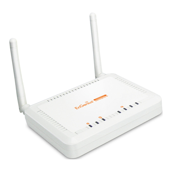
Page 5: Product Layout
1.2. Product Layout Description 1 ( Link-> blue on, traffic->blink) WLAN 1 ( Link-> blue on, traffic->blink) Power/Status 1 ( On-> red Test/reset default->blink) -
Page 6: System Requirements
1.3. System Requirements To begin using the ERB9250, make sure you meet the following as minimum requirements: Existing AP / Router PC/Notebook. Operating System – Microsoft Windows 98SE/ME/XP/2000/VISTA 1 Free Ethernet port. WiFi card/USB dongle (802.11b/g/n) – optional. External xDSL (ADSL) or Cable modem with an Ethernet port (RJ-45). -
Page 7: Installation
2. Installation Please configure your PC / Notebook Ethernet card IP address before device configuration. 2.1. PC Network Adapter setup (Windows XP) Enter [Start Menu] select [Control panel] select [Network]. Select [Local Area Connection]) icon=>select [properties]... - Page 8 Select [Internet Protocol (TCP/IP)] =>Click [Properties]. Select the [General] tab. ERB9250 supports [DHCP] function, please select both [Obtain an IP address automatically] and [Obtain DNS server address automatically].
-
Page 9: Bring Up Erb9250
2.2. Bring up ERB9250 Connect the supplied power-adapter to the power inlet port and connect it to a wall outlet. Then, ERB9250 automatically enters the self-test phase. Once WLAN LED is on and blinking randomly to indicate that it is in normal operation. -
Page 10: Quick Setup Range Extender
AP. We suggest you place your extender right next to your AP for the initial setup. We can move the extender to further location after configuration is completed. ERB9250 default IP address is 192.168.1.2, please ensure it is not occupied by any other devices. -
Page 11: Manual Configuration
Once the orange WLAN LED stop blinking and staying on, the setup is then completed. If the LED does not stay on, this means the configuration is not successful. In case you do not have the extender right next to your AP, please move your extender closer and make sure the antennas are properly screwed firmly on the devices. - Page 12 8. Click on [Site Survey] to search the existing AP. 9. Few seconds later, a window will pop up a list of available APs. 10. Select your target AP and click on [Connect]. 11. Enter the access key for the target AP and click on [Save]. 12.
-
Page 14: Erb9250 Placement
Generally, placing extender at where the AP signal strength greater than 30% considered suitable. You can place ERB9250 on a desk or other flat surface, or you can mount it on a wall. For optimal performance, place your extender within the coverage of your existing AP from which the signal you would like to extend. - Page 15 between the two nails is 89mm. Finally, carefully mount the device onto the wall and make sure the nails are firmly locked on the mount points. Recommended Screw Dimension: 18mm x 5mm...
-
Page 16: Smart Wizard
5. Smart Wizard Please insert the Wizard CD into your CD-ROM driver. If you are using MacOS or other operation system, please browse your CD and click on index.html to start Smart Wizard. - Page 17 Click on [Quick Setup] if you would like go for Quick Setup. Click on [Manual Setup] if your AP does not support WPS button or Quick Setup does not work on your AP. Click [User Manual] to view user manual Click on [Adobe Reader] to install PDF reader Please follow the instructions given on the screen to proceed.
-
Page 18: Initial Setup Erb9250
6. Initial Setup ERB9250 ERB9250 uses web-interface for configuration to be accessed through your web browser, such as Internet Explorer or Firefox. 1. OPEN your browser (e.g. Internet Explorer). Type http://192.168.1.2 in address bar and hit [Enter] button on your keyboard. -
Page 20: System
7. System 7.1. Operation Mode This page allows you to change device operation mode. ERB9250 supports Universal Repeater (Range Extender) and Client Bridge mode. By default it is configured as an Universal Repeater (also known as Extender). If you are not sure what Client Bridge is, please do not use this mode. Client Bridge is not an AP extender but an “Ethernet Wireless Extender”. -
Page 21: Event Log
7.3. Event Log View operation event log. This page shows the current system log of the Broadband router. It displays any event occurred after system start up. At the bottom of the page, the system log can be saved <Save> to a local file for further processing or the system log can be cleared <Clear>... -
Page 22: Monitor
7.4. Monitor Show histogram for network connection on WAN, LAN & WLAN. Auto refresh keeps information updated frequently. 7.5. DHCP (CR Mode) View the current LAN clients which are assigned with an IP Address by the DHCP- server. This page shows all DHCP clients (LAN PCs) currently connected to your... -
Page 23: Schedule (Cr Mode)
network. The table shows the assigned IP address, MAC address and expiration time for each DHCP leased client. Use the <Refresh> button to update the available information. Hit <Refresh> to get the updated table. You can check “Enable Static DHCP IP“. It is possible to add more static DHCP IPs. They are listed in the table “Current Static DHCP Table“. - Page 24 Edit schedule options to allow configuration of firewall and power savings services. Fill in the schedule and select type of service. Click <Apply> to keep the settings.
-
Page 25: Wireless
8. Wireless 8.1. Status 8.2. Basic Radio: You can turn on/off wireless radio. If wireless Radio is off, you cannot associate with AP through wireless. Mode: In this device, we support three operation modes which are AP router and AP route with WDS. If you choose AP Router Mode, you can select AP or WDS function in the drop-down menu. - Page 26 Band: You can select the wireless standards running on your network environment. 2.4 GHz(B): If all your clients are 802.11b, select this one. 2.4 GHz(N): If all your clients are 802.11n, select this one. 2.4 GHz(B+G): Either 802.11b or 802.11g wireless devices are in your environment.
-
Page 27: Advanced
8.3. Advanced Fragment Threshold: This specifies the maximum size of a packet during the fragmentation of data to be transmitted. If you set this value too low, it will result in bad performance. RTS Threshold: When the packet size is smaller than the RTS threshold, the wireless router will not use the RTS/CTS mechanism to send this packet. -
Page 28: Security
N Data Rate: The “Data Rate” is the rate that this access point uses to transmit data packets for N compliant wireless nodes. Highest to lowest data rate can be fixed. Channel Bandwidth: This is the range of frequencies that will be used. Preamble Type: The “Long Preamble”... -
Page 29: Wep Encryption
WMM: Wi-Fi MultiMedia if enabled supports QoS for experiencing better audio, video and voice in applications. Encryption: When you choose to disable encryption, it is very insecure to operate ERB9250. 8.4.1. WEP Encryption When you select 64-bit or 128-bit WEP key, you have to enter WEP keys to encrypt data. -
Page 30: Wpa Pre-Shared Key Encryption
Key Length: You can select the WEP key length for encryption, 64-bit or 128-bit. The larger the key will be the higher level of security is used, but the throughput will be lower. Key Type: You may select ASCII Characters (alphanumeric format) or Hexadecimal Digits (in the "A-F", "a-f"... -
Page 31: Filter
frequently. So the encryption key is not easy to be cracked by hackers. This is the best security available. 8.5. Filter This wireless router supports MAC Address Control, which prevents unauthorized clients from accessing your wireless network. Enable wireless access control: Enable the wireless access control function Adding an address into the list Enter the "MAC Address"... -
Page 32: Client List
WPS button on the device. 8.8. AP Profile (CB/ CR Mode) This page allows you to edit your AP profiles. ERB9250 allows you to keep multiple AP candidates. AP on the top of the list has higher precedence than those on the bottom. -
Page 33: Network
Click [Add] to create new profile. Click [Edit] to create new profile. SSID: enter the SSID of the target AP Encryption: select the Encryption method Authentication Type: select authentication type Pre-shared key: enter the key of for security setting. Click [Move Up] to move the record up Click [Move Down] to move the record down Click [Delete Selected] to remove the chosen profile Click [Delete All] to remove all profiles. -
Page 34: Lan
9.2. LAN IP address: 192.168.0.1. It is the router’s LAN IP address (the “Default Gateway” IP address of your LAN clients). It can be changed based on your own choice. IP Subnet Mask: 255.255.255.0 Specify a Subnet Mask for your LAN segment. Default Gateway: please specify gateway IP if any. -
Page 35: Dmz (Demilitarized Zone)
10.2. DMZ (Demilitarized Zone) If you have a client PC that cannot run an Internet application (e.g. Games) properly from behind the NAT firewall, then you can open up the firewall restrictions to unrestricted two-way Internet access by defining a DMZ Host. The DMZ function allows you to re-direct all packets going to your WAN port IP address to a particular IP address in your LAN. -
Page 36: Dos (Denial Of Service)
10.3. DoS (Denial of Service) The Broadband router's firewall can block common hacker attacks, including Denial of Service, Ping of Death, Port Scan and Sync Flood. If Internet attacks occur the router can log the events. Ping of Death: Protections from Ping of Death attack. Discard Ping From WAN: The router’s WAN port will not respond to any Ping requests Port Scan: Protects the router from Port Scans. - Page 37 Enable MAC Filtering: Check to enable or disable MAC Filtering. Deny: If you select “Deny” then all clients will be allowed to access Internet except the clients in the list below. Allow: If you select “Allow” then all clients will be denied to access Internet except the PCs in the list below.
-
Page 38: Ip Filter
Click <Apply> at the bottom of the screen to save the above configurations. 10.5. IP Filter Enable IP Filtering: Check to enable or uncheck to disable IP Filtering. Deny: If you select “Deny” then all clients will be allowed to access Internet except for the clients in the list below. -
Page 39: Url Filter
10.6. URL Filter Enable URL Blocking: Enable or disable URL Blocking Add URL Keyword Fill in “URL/Keyword” and then click <Add>. You can enter the full URL address or the keyword of the web site you want to block. If you happen to make a mistake and want to retype again, just click "Reset"... -
Page 40: Advanced (Cr Mode)
Click <Apply> at the bottom of the screen to save the above configurations 11. Advanced (CR Mode) 11.1. NAT Network Address Translation (NAT) Network Address Translation (NAT) allows multiple users at your local site to access the Internet through a single Public IP Address or multiple Public IP Addresses. NAT provides Firewall protection from hacker attacks and has the flexibility to allow you to map Private IP Addresses to Public IP Addresses for key services such as Websites and FTP. - Page 41 Enable Port Mapping: Enable or disable port mapping function. Description: description of this setting. Local IP: This is the local IP of the server behind the NAT firewall. Protocol: This is the protocol type to be forwarded. You can choose to forward “TCP”...
-
Page 42: Port Forwarding
click D<Delete Selected>. If you want to remove all Port Mapping settings from the table, click <Delete All> button. Click <Reset> will clear your current selections. Click <Apply> at the bottom of the screen to save the above configurations. 11.3. Port Forwarding Use the Port Forwarding (Virtual Server) function when you want different servers/clients in your LAN to handle different service/Internet application type (e.g. -
Page 43: Port Triggering
(service/Internet application) port number from the Internet that will be re-directed to the above Private IP address host in your LAN Network. Public Port: Port number will be changed to Local Port when the packet enters your LAN Network. Add Port Forwarding Fill in the "Description"... - Page 44 Enable Trigger Port: Enable or disable the Port Trigger function. Trigger Port: This is the outgoing (Outbound) range of port numbers for this particular application. Trigger Type: Select whether the outbound port protocol is “TCP”, “UDP” or “BOTH”. Public Port: Enter the In-coming (Inbound) port or port range for this type of application (e.g.
-
Page 45: Alg
Triggering setting will be added into the "Current Trigger-Port Table" below. If you happen to make a mistake, just click <Reset> and the fields will be cleared. Remove Port Triggering If you want to remove Special Application settings from the "Current Trigger-Port Table", select the Port Triggering settings you want to remove in the table and then click <Delete Selected>. -
Page 46: Qos
Enable/Disable UPnP: You can enable or Disable the UPnP feature here. After you enable the UPnP feature, all client systems that support UPnP, like Windows XP, can discover this router automatically and access the Internet through this router without having to configure anything. The NAT Traversal function provided by UPnP can let applications that support UPnP connect to the internet without having to configure the virtual server sections. - Page 47 Unlimited Priority Queue: The LAN IP address will not be bounded in the QoS limitation. High/Low Priority Queue: This can put the packets in the protocol and port range to High/Low QoS Queue. Bandwidth Allocation: This can reserve / limit the throughput of specific protocols and port range. You can set the upper bound and Lower bound.
- Page 48 Type: Specify the direction of packets. Upload, download or both. IP range: Specify the IP address range. You could also fill one IP address Protocol: Specify the packet type. The default ALL will put all packets in the QoS priority Queue. Port range: Specify the Port range.
-
Page 49: Static Routing
11.8. Static Routing You can set enable Static Routing to let the router forward packets by your routing policy. Destination LAN IP: Specify the destination LAN IP address of static routing rule. Subnet Mask: Specify the Subnet Mask of static routing rule. Default Gateway: Specify the default gateway of static routing rule. -
Page 50: Dynamic Routing
11.9. Dynamic Routing This page allows you to configure Dynamic Routing. 11.10. Routing Table The page shows the device routing table. 12. Management 12.1. Admin You can change the password required to log into the broadband router's system web-based management. By default, the password is: admin. Passwords can contain 0 to 12 alphanumeric characters, and are case sensitive. -
Page 51: Firmware
Old Password: Fill in the current password to allow changing to a new password. New Password: Enter your new password and type it again in Repeat New Password for verification purposes Idle Timeout: enter Administration Page timeout. 12.2. Firmware This page allows you to upgrade the router’s firmware. To upgrade the firmware of your Broadband router, you need to download the firmware file to your local hard disk, and enter that file name and path in the appropriate field on this page. -
Page 52: Reset
This page allows you to save the current router configurations. When you save the configurations, you also can re-load the saved configurations into the router through the Restore Settings. If extreme problems occur you can use the Restore to Factory Defaults to set all configurations to its original default settings. 12.4. - Page 53 Time Zone: Select the time zone of the country you are currently in. The router will set its time based on your selection. NTP Time Server: The router can set up external NTP Time Server. Daylight Savings: The router can also take Daylight Savings into account. If you wish to use this function, you must select the Daylight Savings Time period and check/tick the enable box to enable your daylight saving configuration.
-
Page 54: Ddns (Cr Mode)
PC Date and Time: This field would display the PC date and time. Daylight Savings: The router can also take Daylight Savings into account. If you wish to use this function, you must select the Daylight Savings Time period and check/tick the enable box to enable your daylight saving configuration. -
Page 55: Diagnosis
Enable/Disable DDNS: Enable or disable the DDNS function of this router Server Address: Select a DDNS service provider Host Name: Fill in your static domain name that uses DDNS. Username: The account that your DDNS service provider assigned to you. Password: The password you set for the DDNS service account above Click <Apply>... -
Page 56: Logout
14. Logout Click on [Logout] button to logout. -
Page 57: Appendix A - Fcc Interference Statement
Appendix A – FCC Interference Statement Federal Communication Commission Interference Statement This equipment has been tested and found to comply with the limits for a Class B digital device, pursuant to Part 15 of the FCC Rules. These limits are designed to provide reasonable protection against harmful interference in a residential installation. -
Page 58: Appendix B - Ic Interference Statement
Appendix B – IC Interference Statement Industry Canada statement: This device complies with RSS-210 of the Industry Canada Rules. Operation is subject to the following two conditions: (1) This device may not cause harmful interference, and (2) this device must accept any interference received, including interference that may cause undesired operation.