Table of Contents
Advertisement
Quick Links
Advertisement
Table of Contents

Related Manuals for Bosch TC9346A Series


Summary of Contents for Bosch TC9346A Series
- Page 1 TC9346A Series Instruction Manual EN Environmental Enclosure...
-
Page 2: Table Of Contents
Figure Page Exploded Assembly Diagram for Blower and Circuit Board ....5 TC9346A Series Input Wiring Diagram ..........9 Component Locations for Optional Circuit Board ......12 Layout of Traces on Optional Circuit Board ........12 Wiring Diagram for Optional Circuit Board (O/I-PCB) ....... 13 TC9346A Dimension Drawing ............ -
Page 3: General
1.0 GENERAL 1.1 IMPORTANT SAFEGUARDS AND WARNINGS Prior to installation and use of this product, the following WARNINGS should be observed. Installation and servicing should only be done by qualified service personnel and conform to all local codes. Unless the unit is specifically marked as a NEMA Type 3, 3R, 3S, 4, 4X, 6, or 6P enclosure, it is designed for indoor use only and it must not be installed where exposed to rain and moisture. -
Page 4: Description
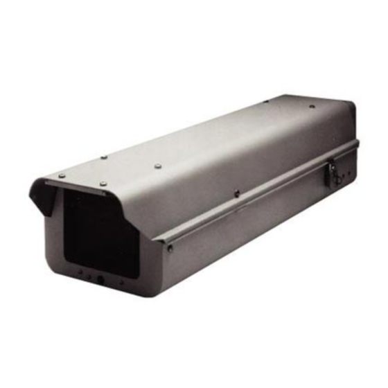
2.0 DESCRIPTION Environmental enclosures in the TC9346A Series are used with pan/tilt units or fixed mounts. The enclosures are constructed of aluminum. You can install cameras with either fixed focal length lenses or motorized zoom lenses. All models have an adjustable camera sled to accommodate different sizes of cameras and lenses. -
Page 5: Installation
3.0 INSTALLATION Unlatch and raise the enclosure lid. The gas spring will hold the lid in place when it is fully opened. Remove the camera sled from the rail: Loosen the screws. Slide the sled so that the screws are in the large part of the mounting slots. - Page 6 Remove the four screws and washers (B and D) that secure the fan to the fan plate. Turn the fan around so that it blows toward the viewing window (refer to the arrows on the fan). Reinstall the fan on the fan plate. Reinstall the fan plate and fan in the enclosure.
- Page 7 Wire the 10-connector INPUTS terminal on the circuit board to the lens controller as follows: • Lens Common - Connector 1 • Focus - Connector 2 • Zoom - Connector 3 • Iris - Connector 4 • Preset Common - Connector 5 •...
- Page 8 13. TC9346A-1, -2, -3 Models Only Wire power to the enclosure to operate accessories (and the camera if its power is connected to CAM 1 on the circuit board) as follows: Remove the plastic cover over the power supply section of the circuit board.
-
Page 9: Tc9346A Series Input Wiring Diagram
VOLTAGE HIGH CAUTION WASH WIPEON PRST ZOOM PRST FOCUS PRST PRST IRIS ZOOM FOCUS LENS GRN/WHT RED/WHT USED YEL/WHT BLK/WHT WHT/BLU WHT/RED WHT/BRN WHT/ORG Figure 2. TC9346A Series Input Wiring Diagram... -
Page 10: A 24 Vac Wiring Distances
Table A. 24 VAC Wiring Distances The following are the recommended maximum distances for 24 VAC applications and are calculated with a 10-percent voltage drop. (Ten percent is generally the maximum allowable voltage drop for AC-powered devices.) EXAMPLE: An enclosure that re- Wire Gauge quires 80 vA and is installed 35 feet (10 m) from the transformer would... -
Page 11: Operation
4.0 OPERATION If your enclosure has a thermostatically controlled blower, the thermostat is set to turn the fan on between 77 and 93 F (25 and 34 C) and to turn the fan off be- tween 62 and 78 F (17 and 26 C). If your enclosure has thermostatically controlled heaters or defroster, the thermo- stat is set to turn them on between 42 and 58 F (6 and 14 C) and to turn them off between 72 and 88 F (22 and 31 C). -
Page 12: Maintenance And Troubleshooting
5.0 MAINTENANCE AND TROUBLESHOOTING 5.1 MAINTENANCE Perform the following maintenance at regularly scheduled intervals to prolong the operational life and appearance of the equipment. Clean the window with a mild non-abrasive detergent in water and a soft cloth to maintain picture clarity. If your enclosure has a blower, clean the foam filters as follows: On the bottom front of the enclosure, remove the two screws in the vent grill. -
Page 13: Wiring Diagram For Optional Circuit Board (O/I-Pcb)
ENCLOSURE CIRCUIT BOARD REFER TO FIGURE 3 FOR COMPONENT LOCATIONS Figure 5. Wiring Diagram for Optional Circuit Board (O/I-PCB) -
Page 14: Specifications
6.0 SPECIFICATIONS ELECTRICAL Input Voltage: 24, 120 or 230 VAC, 50/60 Hz Electrical Connections: One each of the following when equipped with optional circuit board (O/I-PCB): 3-connector terminal block for power input 6-pin lens connector 9-connector terminal block for lens wiring 10-connector terminal block for camera/lens wiring 2-connector terminal block for spare connections 3-pin socket for camera power input... -
Page 15: Tc9346A Dimension Drawing
GENERAL NEMA Rating: 3R (4 when vent cover plates are used) iec 144 rating: IP32 (IP56 when vent cover plates are used) Environment: Indoor/outdoor -10 to 120 F (-23 to 49 C) (Design and product specifications subject to change without notice.) 10.55 (26.79) 5.25... - Page 16 The Netherlands Republic of Singapore Fax: 1-717-735-6560 Tele +31 40 27 80000 Tel: 65 (6) 319 3486 www.boschsecuritysystems.com © 2004 Bosch Security Systems GmbH 3935 890 12912 04-33 | Updated August 10 2004 | Data subject to change without notice.