Ariston microSYSTEM 21 RFFI Installation Instructions Manual
Type c boilers
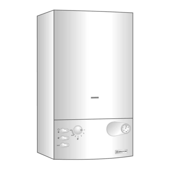
Hide thumbs
Also See for microSYSTEM 21 RFFI:
- User manual (16 pages) ,
- Installation instructions manual (48 pages)

Related Manuals for Ariston microSYSTEM 21 RFFI


Summary of Contents for Ariston microSYSTEM 21 RFFI
- Page 1 Installation Instructions Type C Boilers G.C.N: 41-116-06 41-116-07 LEAVE THESE INSTRUCTIONS WITH THE END-USER Country of destination: GB/IE...
-
Page 2: Table Of Contents
TABLE OF CONTENTS GENERAL INFORMATION 1.1 G ENERAL NSTRUCTIONS 1.2 O VERALL INSTALLATION 2.1 D ELIVERY 2.2 R EFERENCE TANDARDS 2.3 S ITING THE PPLIANCE 2.4 O VERALL IMENSIONS 2.5 C LEARANCES 2.6 M OUNTING THE PPLIANCE 2.7 E LECTRICAL ONNECTION 2.8 G ONNECTION... -
Page 3: General Information
This manual is an integral and essential part of the product. It should be kept GENERAL with the appliance so that it can be consulted by the user and our authorised INFORMATION personnel. Please carefully read instructions and notices about the User’s unit contained in this manual, as Manual... -
Page 4: Verall View
4 - Visual check of the combustion process or analysis of combustion by- products (see section 4.5) and cleaning of the burner if needed. 5 - If called for by point. 3, dismantling and cleaning of the combustion chamber. 6 - If called for by point. 4, dismantling and cleaning of the burner jets. 7 - Visual check of the primary heat exchanger: check for overheating in the blade assembly;... -
Page 5: Installation
The technical information and instructions provided herein below are INSTALLATION intended for the installer / Servicing Technician so that the unit may be installed and serviced correctly and safely. There will be two items: ELIVERY 1 - The fully assembled boiler 2 - A separately boxed connection ki WATER REGULATIONS EFERENCE... -
Page 6: Iting The Appliance
WARNING!! The addition of anything that may interfere with the normal operation of the appliance without express written permission of the manufacturer or his agent could invalidate the warranty. In GB this could also infringe the GAS SAFETY(Installation and Use) REGULATIONS. In the Republic of Ireland the installation and initial start up of the appliance must be carried out by a Competent Person in accordance with the current edition of I.S.813 “Domestic Gas Installations”, the current Building... -
Page 7: Verall Dimensions
VERALL IMENSIONS EGEND 60 mm = Central Heating Flow (3/4”) = Gas Inlet (3/4”) = Central Heating Return (3/4”) mm = Clearances LEARANCES 450 mm In order to allow for access to the interior of the boiler for maintenance pur poses, the boiler must be installed in compliance with the minimum clearances indicated in F . -
Page 8: As Connection
marked “L”. Note: The diagrams for the electrical system are indicated in section 2.12. Warning, this appliance must be earthed. External wiring must be correctly earthed, polarised and in accordance with relevant regulations / rules. In GB this is the current I.E.E. WIRING REGULATIONS. - Page 9 ENTRAL EATING Detailed recommendations are given in BS 6798:1987 and BS 5449-1:1990, the following notes are given for general guidance. Copper tubing to BS EN 1057:1996 is recommended for water pipes. Jointing should be either with capillary soldered or compression fittings. Where possible pipes should have a gradient to ensure air is carried naturally to air release points and water flows naturally to drain taps.
-
Page 10: Lue Connection
2.10 F YSTEM ONNECTIONS The provision for satisfactory flue termination must be made as described in BS 5440-1, for IE recommendations I.S.813. The appliance must be installed so that the flue terminal is exposed to outdoor air, consideration must be given to terminal discharges onto a pathway or passageway, check that the combustion discharges will not cause a nuisance and that the terminal will not obstruct the passageway. - Page 11 In addition, it is also possible to use a split (twin pipe) system by fitting a special adaptor to the flue connector and using the aperture for the air vent intake located on the top part of the combustion chamber. To utilise the air intake it is necessary to: 1.
- Page 12 ABLE Maximum Risk of Condensation Forming Exhaust Restrictor ø 46 mm Extension Type Piping not insulated Piping insulated 21 RFFI Exhaust/Air ø 46 ø 46 restrictor NO restrictor restrictor NO restrictor C12 (xx) Coaxial L min = 0.5 m L = 4 m C32 (xx) Systems NONE...
-
Page 13: Oom Thermostat Connection
2.11 R To connect a room thermostat and/or time clock, it is necessary to: HERMOSTAT ONNECTION 1. - Open the control panel as indicated in section 4.3; 2.- Remove screws “A” and remove the inspection cover from the reverse of the control panel;... -
Page 14: Lectrical Diagrams
2.12 LECTRICAL IAGRAM A11 - Overheat Thermostat EGEND A12 - Spark Generator/Gas Valve Supply A - On/Off Switch A13 - Detection Electrode B - On/Off L.E.D. C - Heating Switch Colours: D - Heating L.E.D. -White E - Reset Button -Blue F - Ignition Failure (Lockout) L.E.D. -
Page 15: Gas And Water Circuits
. 2.13 2.13 AS AND ATER IRCUITS EGEND . 2.14 Main heat exchanger Overheat thermostat Burner Ignition electrodes Detection electrode Regulation thermostat Frost thermostat Gas valve 10. Pump pressure switch 11. Safety valve (3 bar) 12. Boiler drain valve 13. Automatic by-pass 14. -
Page 16: Storage Cylinder
(D.H.W.). Cylinders of different CYLINDER capacities can be used depending on site requirements (see T 3.1 for a ABLE selection of ARISTON unvented cylinders). PORT AND PORT ALVE NSTALLATIONS 2 port valve installation 3 port valve installation . - Page 17 Wiring to 3 port valve installation using an external 2 channel programmer Type Danfoss FP715 Type Honeywell ST6400C : When using a 3 port valve installation in conjunction with an unvented cylinder it . 3.4 will be necessary to use a 2 port valve on the cylinder flow connection in addition to the 3- port valve to satisfy Building Regulations.
-
Page 18: Hot
Comfort STI 125 Indirect The kit (ARISTON part number 706329 ) can be obtained from an Contract STI 150 Indirect ARISTON supplier. -
Page 19: Ontrol Panel
If the gas supply for the boiler serves other appliances ensure that an adequate supply is available both to the boiler and the other appliances when they are in use at the same time. Pipe work must be of an adequate size. Pipes less than the 22mm should not be used. -
Page 20: Initial Start Up
To dismantle the front casing panel it is necessary to: 1 - Remove the two screws “B”; 2 - Move the front casing panel up and lift forward. 4.4 I NITIAL TART HE CHECKS TO BE RUN BEFORE INITIAL START UP ARE AS FOLLOWS 1. -
Page 21: Ombustion
OMBUSTION NALYSIS readings can be The flue connector has two apertures, . 4.2 taken for the temperature of the combustion by-products and of the combustion air, as well as of the concentrations of O and CO , etc. . To access these intakes it is necessary to unscrew the front screw and remove the metal plate with sealing gasket. -
Page 22: Raining The System
The heating system must be emptied as follows: RAINING THE YSTEM - Turn off the boiler; - Attach a hose pipe and open the drain valve; - Empty the system at the lowest points (where present). When the heating system is unused for an extended period of time, it is recommended that you add antifreeze with an ethylene glycol base to the water in the heating lines and radiators if the ambient temperature drops below 0°C during the winter. -
Page 23: W Ater C Onnections
. 5.1 It is recommended that the following inspections be carried out on the MAINTENANCE boiler at least once a year: 1 - Check the seals for the water connections; replace any faulty seals. 2 - Check the gas seals; replace any faulty gas seals. 3 - Visual check of the entire unit. -
Page 24: Technical Information
TECHNICAL INFORMATION 28 RFFI 21 RFFI CE Certification 63AU4549 63AU4549 Heat Input max/min kW 22.7/10.0 29.8/12.0 Heat Output max/min kW 21.0/8.7 27.8/10.5 Efficiency of Nominal Heat Input 92.8 93.5 Efficiency at 30% of Nominal Heat Input 90.8 90.7 Heat Loss to the Casing (∆T=50°C) Flue Heat Loss with Burner Operating Flue Heat Loss with Burner Off Maximum Discharge of Fumes (G20)