Table of Contents
Advertisement
Advertisement
Table of Contents

Related Manuals for Foxconn AT-5250


Summary of Contents for Foxconn AT-5250
- Page 1 NanoPC User’s Manual...
- Page 2 Trademark: Safety Notice: All trademarks are the property of their respective owners. Before using this product, please read the below safety notice carefully, this will help to extend the product’s lifecycle, and work normally. Version: ■ When NanoPC is working, please make sure its ventilation system is working. User’s Manual V1.2 for NanoPC. ■ The power adapter is dissipating heat during normal use, please be sure not to cover it and keep it away from your body to prevent discomfort or injury by heat exposure. ■ Please use the power adapter that comes with the product’s package, wrong power Symbol description: adapter may damage your device. ■ Make sure all the peripherals are properly connected before using NanoPC. Note: Refers to important information that can help you to use NanoPC better, and ■ This product should only be used in an environment with ambient temperatures...
-
Page 3: Table Of Contents
Package Contents TABLE OF CONTENTS Introduction 1-1 Front Side View ...................... 2 1-2 Back Side View ....................... 4 NanoPC Seat Base VESA Mount Placement and connecting 2-1 Placement of NanoPC ................... 7 Erected on the desk....................7 Installing to Display....................7 2-2 Connection of NanoPC ..................10 Connect display ...................... 10 Connect USB devices..................... 11 Power Adapter Power Cord Easy Guide Connect network cable ................... 11 Connect power cord ....................12 BIOS Setup Enter BIOS Setup ....................... - Page 4 Security ........................21 BootOptions ........................ 22 Save & Exit ......................... 23 Install OS 4-1 Install Windows 7 ....................26 4-2 Install Drivers ......................30 Utility Fox WINFLASH ......................32 Introduction 1. Local Update ...................... 32 2. About & Help....................... 34 ■ Front Side View ■ Back Side View...
-
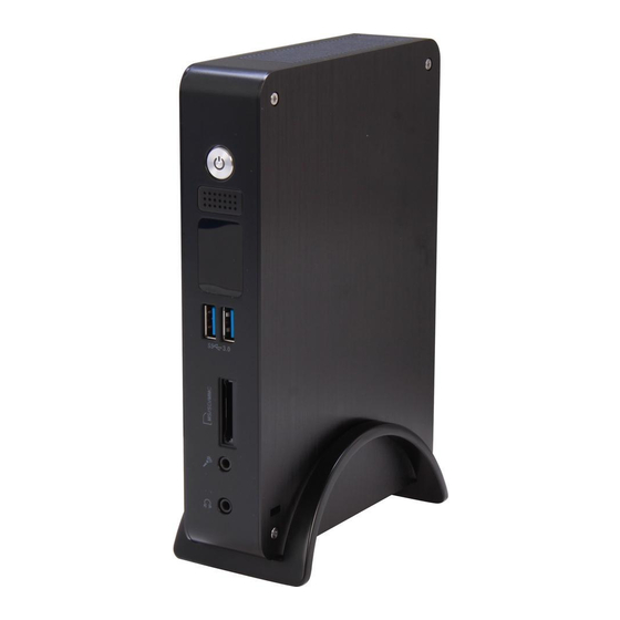
Page 5: Introduction 1-1 Front Side View
INTRODUCTION INTRODUCTION 1-1 Front Side View Power button with Power indicator LED Press to turn your NanoPC on or off, the LED can indicate your system states. Speaker USB 3.0 port This USB port supports the USB 3.0/2.0/1.0 specification. Use this port for USB devices such as keyboard, mouse, USB printer, USB flash drives and hard disk drives, etc. You need to install the USB 3.0 driver in NanoPC USB Disk before using it. Multi-Function card reader This memory card reader supports SD/SDHC/MS/MS Pro/MMC memory cards used in devices like digital cameras, mobile phones, Media players and so on. Microphone / SPDIF in port Connects to a microphone or playback devices with optical connectors (3.5mm jack). SPDIF function requires additional adapter and adapter cable. Headphone Connects to a headphone. Kensington lock Attach a Kensington security system or a compatible security lock to secure your NanoPC in place. -
Page 6: Back Side View
INTRODUCTION INTRODUCTION 1-2 Back Side View USB 2.0 port This USB port supports the USB 2.0/1.0 specification. Use this port for USB devices such as keyboard, mouse, USB printer, USB flash drives and hard disk drives, etc. VGA Port Connect VGA-compatible displays such as a monitor or projector. HDMI port HDMI The HDMI (High-Definition Multimedia Interface) port supports Full-HD display devices. Connect monitor or TV that uses HDMI connector to this port. RJ-45 LAN port Supports 10/100/1000Mb/s Ethernet network. Connect network cable to access Internet. Line out / SPDIF out port Connects to powered analog speakers or recording devices with optical connectors (3.5mm jack). SPDIF function requires additional adapter and adapter cable. Power input port Connect power cord that come with your product. -
Page 7: Placement And Connecting
PLACEMENT AND CONNECTING 2-1 Placement of NanoPC Erected on the desk 1. Place your NanoPC into the groove of the Seat Base. Placement connecting ■ Placement of NanoPC Installing to Display ■ Connection of NanoPC 1. Assemble one side of the VESA mount. - Page 8 PLACEMENT AND CONNECTING PLACEMENT AND CONNECTING 2. Fasten it onto the display with four screws. 4. Install the other side of the VESA mount. 3. Fit the NanoPC into the VESA mount in the correct alignment. T o fasten the VESA mount, your display must comply with VESA75 or VESA100 standard.
-
Page 9: Connect Display
PLACEMENT AND CONNECTING PLACEMENT AND CONNECTING 2-2 Connection of NanoPC Connect USB devices Connect USB devices to the USB ports, for example, mouse, keyboard devices. Connect display There are two USB 3.0 ports on the front side of your NanoPC, you need to install the USB 3.0 driver in NanoPC USB disk before using them. Connect a display or TV that has HDMI port or VGA port to your NanoPC. Connect network cable Connect one end of a network cable to the RJ-45 LAN port, and the other end to a hub or switch. -
Page 10: Bios Setup
PLACEMENT AND CONNECTING Connect power cord Connect the power adapter to the power input port of the NanoPC, and then press the power button to start it. BIOS Setup ■ Enter BIOS Setup ■ Main ■ Advanced ■ Power ■ Security ■ BootOptions ■ Save & Exit The power adapter is dissipating heat during normal use, please do not cover it and keep it away from your body to prevent injury from heat exposure. -
Page 11: Enter Bios Setup
BIOS SETUP BIOS SETUP Enter BIOS Setup Main Aptio Setup Utility - Copyright (C) 2011 American Megatrends, Inc. The BIOS is the communication bridge between hardware and software, correctly setting up the BIOS pa- Main Advanced Power Security BootOptions Save & Exit Main rameters is critical to maintain optimal system performance. Power on the computer, when the message Set the Date. Use Tab to System BIOS switch between Date elements. Project Version B34F1D29 “Press <Del> to enter setup. Press <F11> to enter boot menu.”... -
Page 12: Miscellaneous
BIOS SETUP BIOS SETUP no password is set or you enter system with administrator password, this item will display Miscellaneous “Administrator”. Aptio Setup Utility - Copyright (C) 2011 American Megatrends, Inc. Main Advanced Power Security BootOptions Save & Exit Advanced Select the keyboard NumLock Advanced Bootup Num-Lock [off]... -
Page 13: Integrated Peripherals
BIOS SETUP BIOS SETUP SATA Configuration Integrated Peripherals Aptio Setup Utility - Copyright (C) 2011 American Megatrends, Inc. Main Advanced Power Security BootOptions Save & Exit Advanced Aptio Setup Utility - Copyright (C) 2011 American Megatrends, Inc. Enable/Disable Onboard LAN Main Advanced Advanced Power Security... -
Page 14: Security
BIOS SETUP BIOS SETUP Power Security Aptio Setup Utility - Copyright (C) 2011 American Megatrends, Inc. Aptio Setup Utility - Copyright (C) 2011 American Megatrends, Inc. Main Advanced Power Power Security BootOptions Save & Exit Main Advanced Power Security BootOptions Save & Exit Security Select the highest ACPI sleep Valid Keys:... -
Page 15: Bootoptions
BIOS SETUP BIOS SETUP BootOptions Save & Exit Aptio Setup Utility - Copyright (C) 2011 American Megatrends, Inc. Aptio Setup Utility - Copyright (C) 2011 American Megatrends, Inc. Main Advanced Power Security BootOptions Save & Exit Main Advanced Power Security BootOptions Save & Exit BootOptions Save &... -
Page 16: Install Os
BIOS SETUP Optimal defaults are the best settings of this motherboard. Always load the Optimal defaults after updating the BIOS or after clearing the CMOS values. Select this option and press Enter, it will pop out a dialogue box to let you load the defaults. Select <Yes> and then press <Enter> to load the defaults. Select <No> and press <Enter>, it will not load. By this default, BIOS have set the optimal performance parameters of system to improve the perfor- mances of system components. But if the optimal performance parameters to be set cannot be sup- ported by your hardware devices (for example, too many expansion cards were installed), the system might fail to work. ► Save as User Default Values If you select this option and press <Enter>, a message will be displayed in the screen. Select [Yes] to save the changes done so far as user defaults, select [No] or <ESC> to return to the menu. ► Load User Default Values If you select this option and press <Enter>, a message will be displayed in the screen. Select [Yes] to restore/load the user defaults to all the setup options, select [No] or <ESC> to return to Install OS the menu. ■ Install Windows 7 ■ Install Drivers... -
Page 17: Install Windows 7
INSTALL OS INSTALL OS What kinds of hardware and software you need here: 9. The setup will display the hard disk partitions (160GB, in this example) of your system. If there 1. Windows 7 Install USB Disk / USB DVD-ROM drive and Windows 7 Install CD (Other purchase) were other systems (such as Linux) installed previously, you need select them and click “Drive options 2. NanoPC USB Flash Disk (In this package) (advanced)” to delete them. When all partitions are clean, setup will display the biggest size of your hard drive. 4-1 Install Windows 7 1. Connect the Windows 7 Install USB Disk (or USB DVD-ROM drive) to one USB port of NanoPC. 2. Press power on button to turn on your computer, then press <Del> key to enter BIOS Setup. 3. Put the Windows 7 Install CD into the USB DVD-ROM drive. (If you use the USB DVD-ROM drive) 4. According to the devices you use, set the first boot device to USB device or DVD drives, press <F10> to save changes and exit BIOS. 5. The computer will reboot, and it will start loading the files for installing the Windows 7. 6. When the installation windows popup, set the related items and click “Next” to continue, then click “Install now” button to start the setup. 7. When the license terms appear, choose accept and click “Next” to continue. 8. It will then ask you to select the installation type. Click “Custom (advanced)” to install a new copy of Windows. 10. In the hard disk size screen, you can click the “new” button to create partitions as you need. In this example we are creating a 70GB partition to install Windows. Make your modifications and click “Apply”. To ensure that all Windows features work correctly, Windows might create additional partitions for system files. So you will see a 100MB partition reserved by system after you create a partition. Select the 70GB partition and click “Next” to continue. - Page 18 INSTALL OS INSTALL OS 11. The setup program will then start to install Windows 7 on your hard disk. During the installation, your computer will restart several times. 12. When the installation is complete, setup will prepare your computer for it’s first use. You can then follow the steps to select system settings, create an account, set a password...etc, until the whole process is completed.
-
Page 19: Install Drivers
INSTALL OS 4-2 Install Drivers 1. When the Windows 7 is completely installed, you have to install the necessary drivers before using the NanoPC. Connect the NanoPC USB Flash Disk to your system. 2. Waiting for a few seconds, the main menu will be displayed on the screen. Utility ■ Fox WINFLASH 3. Use these options to install all the drivers for your system. You must click "Intel Chipset Driver" to install it first. After that, you can click ”One Click Setup” and then choose the items you want to install, or you can click on each individual driver to install it manually. 4. After installing all the drivers, you need to restart your NanoPC, then you can start using it. -
Page 20: Utility Fox Winflash
UTILITY UTILITY Fox WINFLASH 1-2 Local Update - Backup BIOS This page can back up your system BIOS. You can click “Backup BIOS”, and key in a file name, then click “Save” to finish the backup operation. The extension of this backup file is “.ROM” for AMI BIOS. Fox WINFLASH is a useful utility to backup and update your system BIOS. Make sure you can remember the file name together with the directory which it is stored, prevented that you may need them to recover your BIOS later. Supporting Operating Systems: ■ Windows 7 (32-bit) Please set the BIOS setting “BIOS Write Protect” or “Super BIOS Protect” to [Disabled] when running this application. 1. Local Update 1-1 Local Update - BIOS Information This page lets you know your system BIOS information. Minimum Exit Key in a BIOS name Click to Save Toolbar Show current BIOS 1-3 Local Update - Update BIOS information This page helps you to update your BIOS from a local file. After click “Update BIOS”, An alert message will be displayed to ensure if you really want to continue, click “Yes” to confirm. A setup wizard will guide you to load a local BIOS file to finish the operation. You must remember from which directory to load your new BIOS file (with an extension of “.ROM” for AMI BIOS) before the setup wizard starts. Note: BIOS Size 32Mb = 32M bit = 4M Byte BIOS Size 16Mb = 16M bit = 2M Byte Please refer to the physical motherboard for details. -
Page 21: About & Help
UTILITY Statement: This device complies with part 15 of the FCC Rules. Operation is subject to the following two conditions: (1) This device may not cause harmful interference, and (2) this device must accept any interference received, including interference that may cause undesired operation. Warning: FEDERAL COMMUNICATIONS COMMISSION INTERFERENCE STATEMENT This equipment has been tested and found to comply with the limits for a Class B digital device, pursuant to part 15 of the FCC Rules. These limits are designed to provide reasonable protection against harmful interference in a residential installation. This equipment generates, uses and can radiate radio frequency energy and, if not installed and used in accordance with the instructions, may cause harmful interference to radio communications. However, there is no guarantee that interference will not occur in a particular installation. If this equipment does cause harmful interference to radio or television reception, which can be determined by turning the equipment off and on, the user is encouraged to try to correct the interference by one or more of the following measures: ▪ Reorient or relocate the receiving antenna. 2. About & Help ▪ Increase the separation between the equipment and receiver. This page shows some information about Fox WINFLASH. ▪ Connect the equipment into an outlet on a circuit different from that to which the receiver is connected. ▪ Consult the dealer or an experienced radio/ TV technician for help. Caution: Any changes or modifications not expressly approved by the grantee of this device could void the user’s authority to operate the equipment. RF exposure warning: This equipment must be installed and operated in accordance with provided instructions and the antenna(s) used for this transmitter must be installed to provide a separation distance of at least 20cm from all persons and must not be co-located or operating in conjunction with any other antenna or transmitter. End-users and installers must be provide with antenna installation instructions and transmitter operating conditions for satisfying RF exposure compliance. - Page 22 Warning statement for Europe: Also, put in the manual which directive to fulfil and also which countries to sell the product. Example of a text to tell which directive has been fulfilled: Hereby, Foxconn, declares that this AT-5000 Series is in compliance with the essential requirements and other relevant provisions of Directive 1999/5/EC.”...