
Related Manuals for Mackie d8b v3


Summary of Contents for Mackie d8b v3
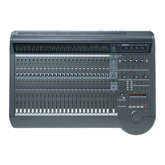
- Page 1 56 input, fully-automated digital mixing console. DIGITAL 8•BUS ™ SERVICE MANUAL This file contains all 110 pages of 8.5" x 11" (to make it easier to print out) ©1999 Mackie Designs Inc. #820-182-00 HOME...
- Page 2 C AU TIO N A V IS R IS K O F E L E C T R IC S H O C K D O N O T O P E N R IS Q U E D E C H O C E L E C T R IQ U E N E P A S O U V R IR C A U T IO N : T O R E D U C E T H E R IS K O F A T T E N T IO N : P O U R E V IT E R L E S...
- Page 3 Additional Safety Information Mackie Designs’ Digital 8•Bus has been tested and conforms to the following standards and directives of the European Council: 73/23/EEC Low Voltage Directive with amendments 91/263/EEC, 89/392/EEC, and 89/336/EEC...
-
Page 4: Table Of Contents
CONTENTS SAFETY PAGES.......2, 3 INTRODUCTION ..................5 TECHNICAL SUPPORT ................5 DISCLAIMER ....................5 OVERVIEW ....................6 COMPUTER SYSTEM ................... 7 DSP SYSTEM ....................9 USER INTERFACE SYSTEM ................ 11 ANALOG SYSTEMS ................... 13 POWER ....................... 13 DSP SIGNAL FLOW, CLOCKS, MUTE ............14 PARTS ....................... -
Page 5: Introduction
Mackie Designs, Service Technical Assistance, is available 8AM - 5PM PST, Monday through Friday for Authorized Mackie Service Centers, at 1-800-258-6883. Feel free to call with any questions and speak with a carefully-calibrated technician. If one is not available, leave a detailed message and a qualified Mackoid will return your call asap. -
Page 6: Overview
Flying Faders, Displays The computer runs Mackie’s real time operating system and handles functions normally associated with a PC such as keyboard, mouse, disk drives, video, etc. The DSP system controls all Digital Signal Processing functions in the console. The User Interface system reads and updates the control surface. -
Page 7: Computer System
These are all standard PC compatible parts. However, because the drivers are written into the Mackie OS, other similar devices may not be compatible. Also, it should be noted that ‘upgrading’ the processor, RAM, or HDD is of little value as the Mackie OS will not take advantage of it. - Page 8 Place the disc in the drive before turning on the Remote CPU. • The computer should start up into DOS from this disc, rather than from the Mackie • Insert any standard DOS diagnostic software and run tests, for example on the hard drive, video card, mother board etc.
-
Page 9: Dsp System
DSP SYSTEM A simplified block diagram of the DSP system is shown on the next page. At the heart of the system is an Analog Devices ADSP-2181. It acts as the console CPU, and controls all functions and communications within the DSP system. There are 24 proprietary DSP chips to handle the actual audio processing. - Page 10 CODEC BOARD -113 ANALOG ANALOG AUDIO AUDIO INPUTS OUTPUTS DSP BOARD -114 WOOP-DEE STATUS LEDS CHIP SELECT LATCH ADSP-2181 IAD0-IAD15 CPU-DSP EPROM A0-A13 TO PC COM-2 D8-D23 UART DSP_TX DSP_RX BACKPLANE BOARD -163 TO BRAIN BOARD AES/EBU CLOCK CLOCK CARD -164 EFFECTS CARD AES/EBU CARD -115 TAPE I/O CARD -119...
-
Page 11: User Interface System
PIC chip. The PIC chip outputs a copyrighted text string so that the d8b can verify the card is original and Mackie-authorized. Cards in which operating parameters can be varied are controlled via the Brain (UI System). The Brain Board also controls all functions on the DCA board. - Page 12 CONTROL SURFACE -120 -121 -122 FADER BOARDS -125 -125 SWITCHES LEDS V-POTS FLYING FADERS x 25 SHIFT SHIFT SHIFT REGISTERS REGISTERS REGISTERS BRAIN BOARD -136 STATUS LEDS LATCHS I/O BUFFERS WHEEL TO VFD ADSP-2181 DRIVER LATCHES CPU-DSP I/O BUFFERS EPROM VU METERS A0-A13 DCA BOARD...
-
Page 13: Analog Systems
ANALOG SYSTEMS The analog circuits used in the d8b should be familiar to anyone with experience servicing Mackie products. The 12 Mic Pre’s are the same circuit which is used in the SR40•8. The line amps use Mackie’s ‘unity plus’ architecture. - Page 14 DSP SIGNAL FLOW The DSP board is the central hub of the signal flow system, the digital signals must find their way to the DSP board, get DSP’d and make their way out again to the big audio ocean. Please take a look at the Block diagrams chapter, especially the diagram on page D3, and the DSP map on the next page.
- Page 15 DSP map This table shows the data received (DR) and data transmitted (DT) by the DSP board. On a scale of 1 to 10, you will find this table fairly useful. INPUT CABLE JUXT SIG NAME(DSP) CABLE SIG NAME OUTPUT LINE 13+14 CODEC U3 J13-3...
- Page 16 DSP CONNECTORS Digital data to This is a compilation of all the DSP board’s and from CODEC connectors, mainly showing the data received and transmitted, and clocks. The power and ground pins are not shown here, to make things a little clearer. These can be found in the connectors chapter, or on the schematics.
- Page 17 CODEC BOARD How it is labeled Analog Analog Connector/pin out of DSP board from DSP The Data transmitted BUS-1 BUS-2 DT_1 J13-1 (DT) from the DSP board is converted to Analog BUS-3 BUS-4 DT_3 J13-5 U152 and split out into its two U252 BUS-5 BUS-6...
- Page 18 CODEC connectors This is a compilation of all the CODEC board’s connectors, mainly showing the analog inputs, data received and transmitted. The power,ground and clocks are not shown, but they can be found in the connectors chapter, or on the schematics. Analog signals Analog signals going out...
- Page 19 DCA connectors This is a compilation of all the DCA board’s connectors, mainly showing the analog inputs, data received and transmitted. The DCA board receives the analog Buses, Auxes, Mixes and Solos from the Analog signals DSP board, then outputs (under coming in from control by the Brain board) to the CODEC board...
- Page 20 TAPE CARDS This shows the analog inputs and outputs on the Tape cards. The analog signals go in and out of the rear panel DB25 connectors J101 and J102 respectively. The Tape cards have their own D/A and A/D converters, therefore, only digital signals are passed to and from the DSP board.
- Page 21 TAPE CARDS continued DIGITAL SIG CARD TO WHAT THE SIGNAL BACKPLANE ANALOG NAME ON BACKPLANE IS CALLED ON TO DSP TAPE OUTPUT TAPE BOARD CONNECTOR THE BACKPLANE CONNECTOR PAIRS AND PIN NO. AND DSP BOARD AND PIN NO. NOTE: All three tape cards 23 AND 24 J20-7,56 DT_8...
- Page 22 EFFECTS CARDS There are four slots available on the backplane board for Effects cards. They can plug into the backplane connectors J51, J16, J14 and J17. The backplane connectors J21 and J24 transmit and receive data to and from the DSP board.In most cases, the digital signals have the same name on the backplane as appear on the DSP board, but there are a few exceptions, shown in the right hand column of the tables below.
- Page 23 EXTRA CARD One slot on the backplane is available for an extra digital I/O card, such as the PDI•8. It connects to backplane connector J22 (in the ALT I/O slot). The signals to and from the DSP board pass through backplane connector J48.
- Page 24 The clock card The clock card generates the main clock signals used throughout the console. On other boards there are a few local clocks used, for example, for the serial Rx and TX connection to the remote CPU. This table shows the signal flow from the clock card to the various boards in the D8B. The clock card fits into connector J23 on the backplane board.
- Page 25 The clocks The diagram below shows the relationship between the various clock signals generated by the clock card. Mackie Serial Digital Audio Format 24 Bit MSB Left Justified L/R CLK DATA SCLK MCLK Data valid on the falling edge of SCLK...
- Page 26 MUTE and UNMUTE On the clock card, there is an important Mute/Unmute circuit. It could have been fitted to any board, but it just so happens it was placed on the clock card. Here is the circuit: The UNMUTE and RESET signals come from the DSP board.
- Page 27 POWER POWER SYSTEM < System Boots DSP > RESET UNMUTE MUTE TIME As the console powers up, the D/A converters are muted on the CODEC board and the TAPE cards. This prevents noise form being heard or recorded on the Analog lines. When the system has finished booting correctly, the all-important UNMUTE signal is sent from the DSP board to this little circuit, and so the D/A converters are unmuted and ready.
- Page 28 QUICK PARTS Ch. 12 to 24 (121 board) Channels 1 to 12 (120 board) TRIM ITEM REFERENCE PART # NEW PART # R105-R1205 130-050-02 R116-R1216 130-049-02 Knob 760-081-00 20dB +40dB 500-018-00 500-037-00 Switch SW107-SW1207 No MIC buttons on 121 board Button 760-078-00 Switch...
- Page 29 ITEM PART # 480-001-00 ITEM PART # 1-24 1-48 Switch SW2601 500-033-02 Switch SW2608 500-033-02 D2609 304-054-02 D2609 304-054-02 Button 760-104-00 Button 760-104-00 LEVEL TO TAPE DIGITAL TRIM Switch SW2602 500-033-02 Switch SW2609 500-033-02 D2602 304-055-02 D2610 304-055-02 Button 760-104-00 Button 760-104-00 AUX 1...
- Page 30 ITEM PART # ITEM PART # STUDIO/SOLO Switch SW16 500-033-02 304-054-02 304-006-00 MIXDOWN SOLO Button 760-104-00 RUDE SOLO LIGHT Switch SW17 500-033-02 304-054-02 Button 760-104-00 PFL SOLO 500-033-02 Switch SW18 304-054-02 130-045-00 Button 760-104-00 AFL SOLO 304-026-00 Knob 760-063-00 Switch SW19 500-033-02 Lens...
- Page 31 PHONES/CUE MIX 1 PHONES/CUE MIX 2 Small Buttons = 760-104-00, later models = 760-117-00 SW20 SW26 SW28 SW30 SW32 Switches = 500-033-02 CLEAR SOLO AUX 9-10 COPY MIX TO CUE AUX 9-10 COPY MIX TO CUE LEDs SW21 SW27 SW29 SW31 SW33 RED = 304-054-02...
- Page 32 7-Segment Displays D200 D202 D204 D206 D208 D210 D200-D211 = 304-035-00 SW86 D201 D203 D205 D207 D209 D211 Small Buttons = 760-104-00, SET TIME later models = 760-117-00 Large Buttons = 760-105-00, BARS BEATS TICKS LOOP SMPTE VIEW later models = 760-118-00 D112 SW103 Switches = 500-033-02...
- Page 33 7-Segment Displays D200 D202 D204 D206 D208 D210 D200-D211 = 304-035-00 SW86 D201 D203 D205 D207 D209 D211 Small Buttons = 760-104-00, SET TIME later models = 760-117-00 Large Buttons = 760-105-00, BARS BEATS TICKS LOOP SMPTE VIEW later models = 760-118-00 D112 SW103 Switches = 500-033-02...
- Page 34 SW22 SW15 SELECT SELECT SELECT SELECT HELP SW13 SW12 PREVIOUS LOW MID HI MID NEXT SW14 SETUP MEMORY A MEMORY B SW23 SW10 SW11 GATE COMPRESSOR PLUG-INS LOAD PATCH SAVE PATCH Small Buttons = 760-104-00, V-Pots later models = 760-117-00 R = 130-045-00 Large Buttons = 760-105-00, D=304-026-00...
- Page 35 SW101 - SW1201 SWITCH =500-037-00 BUTTON = 760-003-00 EXTENDER = 760-028-00 LINE INPUTS BUS OUT 1-8 (BAL /UNBAL) & SURROUND OUT +48V Part of Ribbon J101 - J1201 cable assembly J8 Jacks = 400-223-00 040-143-00 Screws = 700-055-00 Screws = 706-065-00 (4-24 x 3/8) Washer = 710-008-00 LINE IN...
- Page 36 REMOTE CPU QUICK PARTS Ethernet card = 480-026-00 MIDI card Video card = 480-005-00 DRAM Mother board Microprocessor DC power supply cable Fan assembly Computer power supply Hard drive/floppy assembly Bracket = 550-356-00 Switch = 500-040-00 DSUB assembly = 040-276-00 DSUB assembly = 040-282-00 From November 1999, the Remote Power Supply and CPU unit have a new motherboard, a Celeron...
-
Page 37: Parts
D8B MASTER PARTS LIST NOTE: See pages A48-51 for the latest parts lists from July 2001 PART# DESCRIPTION PAGES Parts Numbering guide 040- Cables 090-071-00 D8B CONSOLE A-10,11 090-096-00 D8B REMOTE CPU 12, 13 055- Finished PCB Assy 055-108-00 MIC METER 100- Pots and resistors 055-109-00... - Page 38 090-071-00 DIGITAL 8 BUS CONSOLE REV A1 ITEM PART NO. DESCRIPTION 040-138-00 CBL 3P 22GA .098CL 17IN 040-141-00 RIB 28GA 26C 8IN PLZD 040-142-00 RIB 28GA 40C 8IN PLZD 040-143-00 RIB 28GA 25C 4.5IN DSUB 040-145-00 RIB 28GA 26C 2.5IN PLZD 040-146-00 RIB 28GA 34C 3IN PLZD 040-147-00...
- Page 39 ITEM PART NO. DESCRIPTION 550-278-00 FAB STIFFENER - D8 550-279-00 FAB SHIELD METER - D8 550-280-00 FAB SHIELD DSP - D8 550-283-00 FAB PLATE MOUNT JOG - D8 550-285-00 FAB CARD CAGE 550-287-00 FAB SHIELD AUDIO - D8 550-303-00 SCREEN REAR PANEL D8 550-305-00 FIN PLATE COV AES/EBU 2C 550-307-00...
- Page 40 090-096-XX REV C, REMOTE CPU AND POWER SUPPLY ITEM PART NO. DESCRIPTION 090-096-00 REMOTE PWR SPLY 120V D8 090-096-01 REMOTE PWR SPLY 230V D8 040-139-00 RIB 28GA 34C 23IN PLZD 040-140-00 RIB 28GA 40C 19IN PLZD 040-248-00 DIS 18GA 1010 BLU 14 QDX2 040-276-00 RIB 28GA 20C 7.5 M DSUB 040-282-00...
- Page 41 040-284-00 DIS 18GA BRN/BLU .156 7.5 040-285-00 DIS 26GA 2C 2MM/.100 6.5 055-123-00-01 PCB ASSY LINEAR SPLY - D8 1 see chapter 123, Mackie linear P/S 080-110-00 SA TWISTED PAIR LINEAR SP 410-002-00 INSL SILPAD .007 SELF ADH 480-027-00 SW PWR SPLY ASTEC 5V 22A...
- Page 42 055-108-00 REV A, MIC METER BOARD PART NO. DESCRIPTION VALUE REFERENCE DESIGNATORS 140-064-00 RESISTOR TF SMT R101-124 R201-224 R301-324 R401-424 R501-524 R601-624 212-001-00 CAPACITOR CERAMIC SMT 0.01 C101-103 C201-203 C301-303 C401-403 C501-503 C601-603 304-025-00 LED ARRAY, 12 ELEMENT LED101-102 LED201-202 LED301-302 LED401-402 LED501-502 LED601-602 325-012-03...
- Page 43 055-110-00 REV A, ANALOG I/O PART NO. DESCRIPTION VALUE REFERENCE DESIGNATORS 110-001-00 RESISTOR CF R101-102 R201-202 R301-302 R401-402 R501-502 R601-602 R701-702 R801-802 R901-902 R1001-1002 R1101-1102 R1201-1202 115-373-00 RESISTOR CF 6K81 R103-104 R203-204 R303-304 R403-404 R503-504 R603-604 R703-704 R803-804 R903-904 R1003-1004 R1103-1104 R1203-1204 140-051-00 RESISTOR TF SMT...
- Page 44 055-110-00 REV A, ANALOG I/O continued PART NO. DESCRIPTION VALUE REFERENCE DESIGNATORS 302-015-02 ZTVS DIODE, BI-DIRECTIONAL SA12CA D101-102 D201-202 D301-302 D401-402 D501-502 D601-602 D701-702 D801-802 D901-902 D1001-1002 D1101-1102 D1201-1202 320-012-00 I.C. LINEAR SMD NJM4560M U1-6 400-041-00 CONNECTOR XLR PC MTG VERT MALE J22-23 400-100-00 CONNECTOR JACK 1/4 VERT PC...
- Page 45 055-112-00 REV C, DCA CARD PART NO. DESCRIPTION VALUE REFERENCE DESIGNATORS E1-4 140-025-00 RESISTOR CF R119 R187 R194 R203 R207 R211 R217 R281 R351 140-042-00 RESISTOR TF SMT R256 R261-264 R270-272 R276 R279 140-073-00 RES TF SM .1W 5% 1K0 OHM R50-53 R65-67 R147-150 R164-167 R320-323 R331-334 140-114-00...
- Page 46 055-112-00 REV C continued PART NO. DESCRIPTION VALUE REFERENCE DESIGNATORS 212-025-00 CAPACITOR CERAMIC SMT X7R .1UF C10-11 C15-18 C25 C27-28 C30-31 C34-35 C40-41 C44-48 C54-55 C59 C62 C64-65 C69 C73-74 C76 C79 C82-84 C86 C93-95 C98 C106-109 C112-114 C117-121 C126-129 C134 C138-140 C142 C146-147 C150-152 C158 C162-164 C166 C174-176 C178-179 C182 C185 C188-189 C191 C196-197 C199 C202-204 C209...
- Page 47 055-113-00 REV B, CODEC CARD PART NO. DESCRIPTION VALUE REFERENCE DESIGNATORS 040-315-00 DIS ASSY 18GA UL1010 BLK 3 J100 TM/LUG 140-009-00 RESISTOR TF SMT R10 R56 R110 R156 R200 R210 R256 R310 R356 R410 R456 R510 R556 R610 R656 R710 R756 R810 R856 R910 R956 R1010 R1056 R1110 R1156 140-049-00 RESISTOR TF SMT...
- Page 48 055-113-00 REV B continued PART NO. DESCRIPTION VALUE REFERENCE DESIGNATORS 145-389-00 RESISTOR MF SMT 10K0 R1-2 R4-5 R17-20 R23 R26 R74 R76 R80-81 R84-85 R88-89 R92-93 R96-97 R100-103 R106-107 R117-118 R120-121 R126-127 R130-131 R134-135 R138-139 R142-143 R146-147 R150 R153 R176 R178 R181-182 R185-186 R189-190 R193-194 R196-197 R201-202 R216-219 R226-227 R230-231 R301-302 R317-318 R401-402 R417-418...
- Page 49 055-113-00 REV B continued PART NO. DESCRIPTION VALUE REFERENCE DESIGNATORS 212-031-00 CAPACITOR CERAMIC SMT 68pF C57-58 C61-62 C157-158 C161-162 C257-258 C261-262 C357-358 C361-362 C457-458 C461-462 C557-558 C561-562 C657-658 C661-662 C757-758 C761-762 C857-858 C861-862 C957-958 C961-962 C1057-1058 C1061-1062 C1157-1158 C1161-1162 220-002-02 CAPACITOR LYTIC RADIAL TAPE 47UF C25-26 C67 C69 C167 C169 C267 C269...
- Page 50 055-114-00 REV C, DSP CARD PART NO. DESCRIPTION VALUE REFERENCE DESIGNATORS E1-2 140-025-00 RESISTOR TF SMT R3 R5 R9 R12 R27-32 R34 R43-58 R67 R95-96 R101-102 R137 R172 R213 R248 R255-274 R334-337 R368 R403 R438 R473 R508 R543 R613 R648 R683 R718 R753 R788 R823 R858 R893 R896-903 R906-913 R916-923 R926-933 R936-943 140-042-00...
- Page 51 055-114-00 REV C continued PART NO. DESCRIPTION VALUE REFERENCE DESIGNATORS 325-043-03 OCTAL 3-STATE NONINVERTING 74AC241A U46 U86 U89 U92 U95 U98 BUFFER 325-053-03 IC, SMD, SCH TRIGGER HEX INV. 74AC14 U27 U43 U52 U101 U104 325-054-03 IC, SMD, OCTAL, D-TYP, TRANS 74AC573 LATCH 335-001-00...
- Page 52 055-115-00 REV E, DIGITAL I/O PART NO. DESCRIPTION VALUE REFERENCE DESIGNATORS 080-066-00 PIC PRGMD 115PCB D8 140-025-00 RESISTOR TF SMT 140-049-00 RESISTOR TF SMT R15 R24 R33 R35-37 140-073-00 RESISTOR TF SMT R1 R3 R5-9 R11-14 R18 R21-22 140-097-00 RESISTOR TF SMT R2 R4 R27-29 140-110-00 RESISTOR TF SMT...
- Page 53 055-119-00 REV B, TAPE I/O PART NO. DESCRIPTION VALUE REFERENCE DESIGNATORS J1 J2 080-067-00 PIC PRGMD 119PCB D8 PIC16C54S 140-009-00 RESISTOR TF SMT R10 R56 R110 R156 R210 R256 R310 R356 140-049-00 RESISTOR TF SMT R11-13 R15-16 R35-42 R52 R54-55 R58 R111-113 R115 R152 R154-155 R158 R211-213 R215 R252 R254-255 R258 R311-313 R315 R352 R354-355 R358...
- Page 54 055-119-00 REV B, TAPE I/O continued PART NO. DESCRIPTION VALUE REFERENCE DESIGNATORS 325-053-03 IC,SMD,SCH TRIG HEX INV. 74AC14 329-045-03 D/A CONV SM CS4390 U52 U152 U252 U352 329-046-03 A/D CONV SM CS5360 U3 U103 U203 U303 400-140-00 CONN, DSUB, FEMALE 25P J101-102 450-119-00 PCB, DIGITAL 8-BUS: TAPE I/O...
- Page 55 055-120-00 REV A, MIC/LINE CONTROL SURFACE PART NO. DESCRIPTION VALUE REFERENCE DESIGNATORS 130-045-00 POT 12MM ENDLESS ROT R1301 R1401 R1501 R1601 R1701 R1801 R1901 R2001 R2101 R2201 R2301 R2401 130-050-02 POT 12MM HORIZ, 25MM R105 R205 R305 R405 R505 R605 R705 R805 R905 R1005 R1105 R1205 140-025-00 RESISTOR TF SMT...
- Page 56 055-120-00 REV A continued PART NO. DESCRIPTION VALUE REFERENCE DESIGNATORS 145-361-00 RESISTOR MF SMT 5K11 R118 R121-123 R218 R221-223 R318 R321-323 R418 R421-423 R518 R521-523 R618 R621-623 R718 R721-723 R818 R821-823 R918 R921-923 R1018 R1021-1023 R1118 R1121-1123 R1218 R1221-1223 145-389-00 RESISTOR MF SMT 10K0 R119-120 R219-220 R319-320 R419-420...
- Page 57 055-120-00 REV A continued PART NO. DESCRIPTION VALUE REFERENCE DESIGNATORS 304-054-02 LED, T1, W/TIEBAR T&R SUPER RED D1301 D1307 D1401 D1407 D1501 D1507 D1601 D1607 D1701 D1707 D1801 D1807 D1901 D1907 D2001 D2007 D2101 D2107 D2201 D2207 D2301 D2307 D2401 D2407 304-055-02 LED, T1, W/TIEBAR T&R HI EFF GRN...
- Page 58 055-120-00 REV A continued PART NO. DESCRIPTION VALUE REFERENCE DESIGNATORS 601-004-00 FERRITE BEAD SMB MLB40-5 FB102-103 FB202-203 FB302-303 FB402-403 FB502-503 FB602-603 FB702-703 FB802-803 FB902-903 FB1002-1003 FB1102-1103 FB1202-1203 601-009-00 FERRITE BEAD, SMT Z=1000 FB1-70 FB73 FB75 601-010-00 FERRITE BEAD, SMT Z=73 FB71-72 FB74 FB76-78 706-032-00 LED SPACER, NYLON .300...
- Page 59 055-121-00 REV A, LINE CONTROL SURFACE PART NO. DESCRIPTION VALUE REFERENCE DESIGNATORS 130-045-00 POT 12MM ENDLESS ROT 50KG R1301 R1401 R1501 R1601 R1701 R1801 R1901 R2001 R2101 R2201 R2301 R2401 R2637 130-049-02 POT 9MM HORIZ, 25MM SHAFT 50KG R116 R216 R316 R416 R516 R616 R716 R816 R916 R1016 R1116 R1216 140-025-00 RESISTOR TF SMT...
- Page 60 055-121-00 REV A continued PART NO. DESCRIPTION VALUE REFERENCE DESIGNATORS 145-435-00 RESISTOR MF SMT 30K1 R115 R117 R215 R217 R315 R317 R415 R417 R515 R517 R615 R617 R715 R717 R815 R817 R915 R917 R1015 R1017 R1115 R1117 R1215 R1217 145-485-00 RESISTOR MF SMT 100K R11 R119-120 R219-220 R319-320...
- Page 61 055-121-00 REV A continued PART NO. DESCRIPTION VALUE REFERENCE DESIGNATORS 320-012-00 IC LINEAR SMD NJM4560M U1 U9 U101 U201 U301 U401 U501 U601 U701 U801 U901 U1001 U1101 U1201 321-003-00 IC LINEAR POS 3 TERM LM 7805 VOLTAGE REGULATOR 325-003-03 IC, ANALOG MUX, 8 CH SMD 4051B U5-7 U10...
- Page 62 055-122-00 REV A, OUTPUT CONTROL SURFACE PART NO. DESCRIPTION VALUE REFERENCE DESIGNATORS E1 E3-5 130-045-00 POT 12MM ENDLESS ROT 50KG R1-8 140-025-00 RESISTOR TF SMT R413-416 140-049-00 RESISTOR TF SMT R421 R437-438 R440 R442 140-059-00 RESISTOR TF SMT R11 R23 R27-28 R35-36 R38 R50-54 R57 R60 R62 R64-80 R121 R136-139 R152 R154-155 R186 R195-199 R202-209 140-064-00...
- Page 63 055-122-00 REV A continued PART NO. DESCRIPTION VALUE REFERENCE DESIGNATORS 706-052-00 Z19 Z24-27 760-063-00 Z21 Z36-42 760-064-00 Z22 Z29-35 760-068-01 BUTTON, TRANSPORT REWIND TB20 760-068-02 BUTTON, TRANSPORT F FWD TB15 760-068-03 BUTTON, TRANSPORT STOP TB16 760-068-04 BUTTON, TRANSPORT PLAY TB17 760-068-05 BUTTON, TRANSPORT RECORD...
- Page 64 055-124-00 REV A, 8-WAY FADER PART NO. DESCRIPTION VALUE REFERENCE DESIGNATORS 130-047-00 FADER, 100MM MOTORIZED 10KB R1 R101 R201 R301 R401 R501 R601 R701 140-025-00 RESISTOR TF SMT R30 R37-39 140-049-00 RESISTOR TF SMT R12 R31-32 R45 R47 R56 R112 R212 R312 R412 R512 R612 R712 140-071-00 RESISTOR CF...
- Page 65 055-125-00 REV A, 9-WAY FADER PART NO. DESCRIPTION VALUE REFERENCE DESIGNATORS 130-047-00 FADER, 100MM MOTORIZED 10KB R1 R101 R201 R301 R401 R501 R601 R701 R801 140-025-00 RESISTOR TF SMT R38-41 140-049-00 RESISTOR TF SMT R12 R36-37 R42 R44 R57 R112 R212 R312 R412 R512 R612 R712 R812 140-071-00 RESISTOR CF...
- Page 66 055-136-00 REV A, BRAIN BOARD PART NO. DESCRIPTION VALUE REFERENCE DESIGNATORS 080-057-00 Programed Eprom U38 ZU38 140-042-00 RESISTOR TF SMT R97-98 R101 R103 R111-112 R142 R144-166 R168-170 140-049-00 RESISTOR TF SMT R18-19 R26-27 R39-43 R45 R47 R49-60 R62 R66-69 R71-73 R75-82 R84-90 R96 R99-100 R102 R108-110 R121-130 R171 140-060-00 RESISTOR TF SMT...
- Page 67 055-163-00 REV C, BACKPLANE PART NO. DESCRIPTION VALUE REFERENCE DESIGNATORS 400-077-00 HEADER STR LCK SHRD 20P .100 X 2 J15 J21 J32 400-152-00 CONNECTOR STR LCK SHRD 34P .100 X 2 J24 J47-48 400-200-00 I.S.A. EDGE CONNECTOR 2.54MM J14 J16-20 J22-23 J30 J51 400-221-00 CONNECTOR STR 7P .156 X 1 LOCKING KEYED...
- Page 68 FINAL ASSEMBLY PARTS LIST FOR CE MODELS Parts Numbering guide PART# DESCRIPTION PAGES 040- Cables 090-123-00 D8B CONSOLE CE 41-42 055- Finished PCB Assy 090-126-00 D8B REMOTE CPU 43-45 100- Pots and resistors LATEST PARTS LISTS (JULY 2001) 200- Capacitors 300- Semiconductors PART#...
- Page 69 090-123-00 DIGITAL 8 BUS CONSOLE CE REV A9 PART NO. DESCRIPTION 090-123-00 DIGITAL 8 CONSOLE CE 040-138-00 CBL 3P 22GA .098CL 17IN 040-141-00 RIB 28GA 26C 8IN PLZD 040-142-00 RIB 28GA 40C 8IN PLZD 040-143-00 RIB 28GA 25C 4.5IN DSUB 040-145-00 RIB 28GA 26C 2.5IN PLZD 040-146-00...
- Page 70 090-123-00 CE console, continued PART NO. DESCRIPTION 550-273-00 FAB SUB CHASSIS - D8 550-278-00 FAB STIFFENER - D8 550-279-00 FAB SHIELD METER - D8 550-280-00 FAB SHIELD DSP - D8 550-283-00 FAB PLATE MOUNT JOG - D8 550-285-00 FAB CARD CAGE 550-287-00 FAB SHIELD AUDIO - D8 550-303-00...
- Page 71 090-126-xx REV 12, REMOTE CPU & POWER SUPPLY-CE PART NO. DESCRIPTION 090-126-00 D8 PWR SPLY 120V CE Pre- Nov 99 models 090-126-01 D8 PWR SPLY 230V CE 090-126-02 D8 PWR SPLY 100V CE 040-139-00 RIB 28GA 34C 23IN PLZD 040-140-00 RIB 28GA 40C 19IN PLZD 040-276-00 RIB 28GA 20C 7.5 M DSUB...
- Page 72 090-126-xx REV 12 continued PART NO. DESCRIPTION 740-001-00 TYRAP 3-1/4L 740-003-00 TYRAP 8IN BLK 740-007-01 GROMMET STRIP MEDIUM 740-023-00 FLT CBL CLMP NYL LOCK 40C 760-128-00 DUST COVER 25P DSUB FEM 760-129-00 DUST COVER 25P DSUB MALE 760-130-00 DUST CVR 15HD/9P DSUB SKT Motherboard Changes (see parts list on page A-46) From November 1999, the Remote Power Supply and CPU unit have a new motherboard, Celeron proces- sor, and DIMM memory modules.
- Page 73 The rear panel looks like this, for those units with the new motherboard A-45 PARTS...
- Page 74 090-126-00 REV 16, REMOTE CPU & POWER SUPPLY-CE PART NO. DESCRIPTION 090-126-00 D8 PWR SPLY 120V CE After Nov ‘99 040-139-00 RIB 28GA 34C 23IN PLZD 040-140-00 RIB 28GA 40C 19IN PLZD 040-276-00 RIB 28GA 20C 7.5 M DSUB 040-294-00 CBL DC PWR BRDSHLD D8PWR 055-201-00-01 PCB ASSY PWR DIST D8 PWR...
- Page 75 040-284-00 DIS 18GA BRN/BLU .156 7.5 040-285-00 DIS 26GA 2C 2MM/.100 6.5 055-123-00-01 PCB ASSY LINEAR SPLY - D8 1 see chapter 123, Mackie linear P/S 080-110-00 SA TWISTED PAIR LINEAR SP 410-002-00 INSL SILPAD .007 SELF ADH 480-027-00 SW PWR SPLY ASTEC 5V 22A...
- Page 76 Latest Parts List July 2001 090-123-00 DIGITAL 8 BUS CONSOLE CE REV A3 PART NO. DESCRIPTION 090-123-00 DIGITAL 8 CONSOLE CE 040-138-00 CBL 3P 22GA .098CL 17IN 040-141-00 RIB 28GA 26C 8IN PLZD 040-142-00 RIB 28GA 40C 8IN PLZD 040-143-00 RIB 28GA 25C 4.5IN DSUB 040-145-00 RIB 28GA 26C 2.5IN PLZD...
- Page 77 PART NO. DESCRIPTION 550-273-00 FAB SUB CHASSIS - D8 550-278-00 FAB STIFFENER - D8 550-279-00 FAB SHIELD METER - D8 550-280-00 FAB SHIELD DSP - D8 550-283-00 FAB PLATE MOUNT JOG - D8 550-285-00 FAB CARD CAGE 550-287-00 FAB SHIELD AUDIO - D8 550-303-00 SCREEN REAR PANEL D8 550-307-00...
- Page 78 Latest Parts List July 2001 090-126-00 REV 21, Remote CPU and Power supply PART NO. DESCRIPTION 090-126-00 D8 PWR SPLY 120V CE 040-139-00 RIB 28GA 34C 23IN PLZD 040-140-00 RIB 28GA 40C 19IN PLZD 040-276-00 RIB 28GA 20C 7.5 M DSUB 040-339-00 CBL DC PWR BRDSHLD D8PWR NOTE: New Part Number...
- Page 79 CHIPS Integrated Circuits The following list shows details of the integrated circuits used on each circuit board. If you are viewing this on-screen, click on in the list below, to open up the data sheet for that DATA particular IC. These data sheets are included by kind permission of their respective manufacturers. Many manufacturers offer free data sheets from their websites, so please make sure that you contact them if you need further information.
- Page 80 CHIPS 055-114-00 REV C, DSP CARD 080-058-00 Programmed EPROM 315-004-00 OSCILLATOR 7.3728 MHZ 315-012-00 OSC SMT 22.5792MHZ 22.5792 MHZ 324-004-03 HIGH SPEED CMOS RS-232 ADM232A DATA DRIVERS/RECEIVERS 325-035-03 IC, SMD, HEX INVERTER 74AC04 U110 325-037-03 IC, SMD, DCDR/DEMUX 74AC138 U28-29 U40-42 325-038-03 IC, QUAD, OR, SMD 74AC32...
- Page 81 CHIPS 055-120-00 REV A, MIC/LINE CONTROL SURFACE 304-036-00 LED , TOWER 2MM D1308 D1408 D1508 D1608 D1708 D1808 320-006-00 I.C. LINEAR SMD NJM 2068 U101-102 U201 U301-302 U401 U501-502 U601 U701-702 U801 U901-902 U1001 U1101-1102 U1201 320-012-00 I.C. LINEAR SMD NJM4560M 321-003-00 I.C.
- Page 82 CHIPS 055-123-00 REV E, LINEAR POWER SUPPLY 321-008-00 I.C. ADJ POS 3 TERM LM317T VOLTAGE REGULATOR 321-009-00 I.C. ADJ NEG 3 TERM LM337T VOLTAGE REGULATOR 055-124-00 REV A, 8-WAY FADER 320-004-00 I.C. LINEAR SMD NJM4560 U1-2 U10 U101-102 U201-202 U301-302 U401-402 U501-502 U601-602 U701-702 U904 321-003-00...
- Page 83 CHIPS 055-136-00 REV A, BRAIN BOARD 080-057-00 Programed Eprom 311-005-00 X-SISTOR NPN SMD IMBTA06 315-004-00 OSCILLATOR 7.3728 MHZ 315-006-00 OSCILLATOR 20 MHZ 315-010-00 OSCILLATOR 16 MHZ 320-004-00 I.C. LINEAR SMD NJM4560 U3 U7-8 321-003-00 I.C. LINEAR POS 3 TERM LM 7805 VOLTAGE REGULATOR 324-004-03 HIGH SPEED CMOS RS-232...
-
Page 84: Connectors
CONNECTORS Connectors This table shows each connector and the boards they connect to. Note that the connectors on each board are joined to the same numbered connector on other boards. For example, J4 on the Analog I/O board connects to J4 on the Mic/Line control surface. The following pages show each connector in detail, including the labeling and designation on each pin on either end of the connecting cable. - Page 85 CONNECTORS This is J1 on the power distribution board, not to be confused with the other J1 shown opposite, or J1 on the DSP board. CONNECTORS...
- Page 86 CONNECTORS J1 and J2 ANALOG I/O 110 CODEC 113 The labels for each pin are the same on the Codec board as on the Analog I/O board. In the following pages, where there are slight differences in labeling, both ends of a connector are shown. J1 on DSP (unused) C129 J47 J48...
- Page 87 CONNECTORS CODEC 113 LINE CONTROL SURFACE CONNECTORS...
- Page 88 CONNECTORS J4, J5 and J7 MIC1 PIN2 J4-1 J4-21 MIC7 PIN2 J5-1 J5-21 MIC1 PIN3 J4-2 LINE4 TIP J4-22 MIC7 PIN3 J5-2 LINE10 TIP J5-22 J4-3 LINE4 RING J4-23 J5-3 LINE10 RING J5-23 LINE1 TIP J4-4 J4-24 LINE7 TIP J5-4 J5-24 LINE1 RING J4-5...
- Page 89 CONNECTORS J6-1 J6-2 J6-3 J6-4 J6-5 LINE13 TIP +16V J6-6 LINE13 RING J6-7 J6-8 J6-9 LINE14 TIP LINE14 RING J6-10 J6-11 J6-12 LINE15 TIP LINE15 RING J6-13 J6-14 LINE16 TIP J6-15 -16V LINE16 RING J6-16 J6-17 LINE17 TIP J6-18 LINE17 RING J6-19 J6-20 LINE18 TIP...
- Page 90 CONNECTORS NOTE although the busses are labeled like this on all schematics, they are swapped in software, DCA 112 so Bus1 on schematic = Bus 8 really Bus 2 = Bus 7 really Bus 3 = Bus 6 Bus 4 = Bus 5 Bus 5 = Bus 4 Bus 6 = Bus 3 DB25 connector...
- Page 91 CONNECTORS ANALOG I/O 110 DCA 112 CONNECTORS...
- Page 92 CONNECTORS NOTE although the busses are labeled like this on all schematics, they are swapped in software, so Bus1 on schematic = Bus 8 really Bus 2 = Bus 7 really Bus 3 = Bus 6 Bus 4 = Bus 5 Bus 5 = Bus 4 Bus 6 = Bus 3 Bus 7 = Bus 2...
- Page 93 CONNECTORS J12 and J13 dsp side Codec side CODEC 113 J47 J48 DSP 114 C-10 CONNECTORS...
- Page 94 CONNECTORS BACKPLANE 163 J23 J22 J20 J19 J18 CODEC 113 J16 J17 C-11 CONNECTORS...
- Page 95 CONNECTORS J14, J16 and J17 (on Backplane) C-12 CONNECTORS...
- Page 96 CONNECTORS J18, J19, J20 TAPE I/O CARD 119 BACKPLANE 163 J23 J22 J20 J19 J18 J16 J17 C-13 CONNECTORS...
- Page 97 CONNECTORS J21 and J24 BACKPLANE J23 J22 J20 J19 J18 J47 J48 DSP 114 J16 J17 C-14 CONNECTORS...
- Page 98 CONNECTORS BACKPLANE J23 J22 J20 J19 J18 J16 J17 C-15 CONNECTORS...
- Page 99 CONNECTORS BACKPLANE CLOCK CARD J23 J22 J20 J19 J18 J16 J17 C-16 CONNECTORS...
-
Page 100: Dsp 114
CONNECTORS C108 J47 J48 DSP 114 C-17 CONNECTORS... - Page 101 CONNECTORS BRAIN 136 C-18 CONNECTORS...
- Page 102 CONNECTORS LINE/MASTER METER 109 BRAIN 136 C-19 CONNECTORS...
- Page 103 CONNECTORS MIC/LINE LINE/MASTER METER108 METER 109 C-20 CONNECTORS...
-
Page 104: Digital I/O
CONNECTORS BACKPLANE 163 J23 J22 J20 J19 J18 J16 J17 DIGITAL I/O CARD 115 C-21 CONNECTORS... - Page 105 CONNECTORS BRAIN 136 DCA 112 BACKPLANE J23 J22 J20 J19 J18 BRAIN 136 J16 J17 C-22 CONNECTORS...
- Page 106 CONNECTORS BRAIN 136 C-23 CONNECTORS...
- Page 107 CONNECTORS OUTPUT CONTROL SURFACE BRAIN 136 C-24 CONNECTORS...
- Page 108 CONNECTORS BRAIN 136 LINE CONTROL SURFACE C-25 CONNECTORS...
- Page 109 CONNECTORS BRAIN 136 MIC CONTROL SURFACE C-26 CONNECTORS...
- Page 110 CONNECTORS J38 and J39 MGND=MOTOR GROUND originating all the way back from the Remote CPU's power supply BRAIN 136 8X FADER Note that J38 on the Brain board, connects to J39 on Fader 1. J39 on the Brain board connects to J39 on Fader 2. C-27 CONNECTORS...
- Page 111 CONNECTORS MGND=MOTOR GROUND originating all the way back from the Remote CPU's power supply BRAIN 136 9X FADER C-28 CONNECTORS...
- Page 112 CONNECTORS J50 J41 J42 BRAIN 136 POWER C-29 CONNECTORS...
- Page 113 CONNECTORS J50 J41 J42 J47 J48 POWER DSP 114 J50 J41 J42 ANALOG I/O 110 POWER C-30 CONNECTORS...
-
Page 114: Backplane 163
CONNECTORS J47 and J48 BACKPLANE 163 J23 J22 J20 J19 J18 J47 J48 DSP 114 J16 J17 C-31 CONNECTORS... - Page 115 CONNECTORS BACKPLANE 163 J23 J22 J20 J19 J18 J50 J41 J42 POWER J16 J17 C-32 CONNECTORS...
- Page 116 CONNECTORS BACKPLANE J23 J22 J20 J19 J18 J16 J17 C-33 CONNECTORS...
- Page 117 CONNECTORS DCA 112 LINE CONTROL SURFACE C-34 CONNECTORS...