Table of Contents
Advertisement
Quick Links
Download this manual
See also:
User Manual
Advertisement
Table of Contents

Related Manuals for RME Audio Hammerfall DIGI9652


Summary of Contents for RME Audio Hammerfall DIGI9652
- Page 1 User’s Guide - Macintosh Version ü ü 24 Bit / 96 kHz ® ® SyncAlign PCI Busmaster Digital I/O Card 2 + 24 Channels Stereo / ADAT Interface 24 Bit / 96 kHz Digital Audio ADAT Sync In Board Rev. 1.5, Hardware Version 003...
-
Page 2: Table Of Contents
Contents Introduction .............. 3 Package Contents ............ 3 System Requirements ..........3 Brief Description and Characteristics ......3 Technical Specifications 5.1 Digital..............4 5.2 Digital Interface ............4 5.3 Transfer Modes: Resolution / Bits per Sample ..4 Hardware Installation..........5 Driver Installation ............. -
Page 3: Introduction
1. Introduction Thank you for choosing the RME DIGI9652. This card is capable of transferring digital audio data directly to a computer from practically any device equipped with a digital audio interface, be it S/PDIF, AES/EBU or ADAT optical. The numerous unique features, well thought-out configuration dialog and unsurpassed low latency operation puts the DIGI9652 at the very top of the range of digital audio interface cards. -
Page 4: Technical Specifications
5. Technical Specifications 5.1 Digital Low jitter S/PDIF: < 5 ns in PLL mode (44.1 kHz, optical in) Ultra-low jitter ADAT: < 2 ns in PLL mode (44.1 kHz, optical in) Input PLL ensures zero dropout, even at more than 40 ns jitter Bitclock PLL for trouble-free varispeed operation in ADAT mode High-sensitivity input stage (<... -
Page 5: Hardware Installation
6. Hardware Installation Before installing the DIGI9652, please make sure the computer is switched off and the power cable is disconnected from the mains supply. Inserting or removing a PCI card while the computer is in operation can cause irreparable damage to both motherboard and card! 1. - Page 6 Copy the new files RME DIGI Settings and Hammerfall ASIO into all 'ASIO Drivers' folders found on your computer. As every ASIO software has its own ASIO Drivers folder the files have to be copied several times. The picture to the left shows example after...
-
Page 7: Operation And Usage
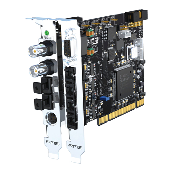
8. Operation and Usage 8.1 Connections Project Hammerfall consists of the main PCI board and an Expansion Board. All the essential electronics are located on the PCI card, so it will also work without the Expansion Board. The main board's bracket has two ADAT optical inputs and two ADAT optical outputs, as well as... -
Page 8: Configuring The Digi9652
9. Configuring the DIGI9652 9.1 General Information Configuring Project Hammerfall is done using its own settings dialog, RME DIGI Settings. The DIGI9652 hardware offers a number of helpful, well thought-of practical functions and options which affect how the card operates - the DIGI9652 can be configured to suit many different requirements. - Page 9 Buffer Size: The setting ‘Buffer Size’ determines the latency between incoming and outgoing data, as well as affecting system stability (see chapter 13). We recommend selecting the highest value here (8192 samples) - the board itself will still run comfortably. SPDIF In: Defines the input for the SPDIF signal.
-
Page 10: Clock Modes - Synchronization
9.2 Clock Modes - Synchronization In the digital world, all devices are either the ‘Master’ (clock source) or a ‘Slave’ synchronized to the master. Whenever several devices are linked within a system, there must always be a single master clock. The DIGI9652’s intelligent clock control is very user-friendly, being able to switch between clock modes automatically. - Page 11 If several digital devices are to be used simultaneously in a system, they not only have to operate with the same sample frequency but also be synchronous with each other. This is why digital systems always need a single device defined as ‘master’, which sends the same clock signal to all the other (‘slave’) devices.
-
Page 12: Word Clock
10. Word Clock 10.1 Technical Description and Usage Correct interpretation of digital audio data is dependent upon a definite sample frequency. Signals can only be correctly processed or transferred between devices if these all share the same clock, otherwise digital signals are misinterpreted, causing distortion, clicks/crackle and even dropouts. -
Page 13: General Operation
10.3 General Operation The green ‘Lock’ LED next to the input jack will light up when the input sees a valid word clock signal. Selecting ‘Word Clock’ in the ‘Clock Mode’ field will switch clock control over to the word clock signal. -
Page 14: Operation Under Asio
13. Operation under ASIO 2.0 13.1 General At the time of writing, Cubase VST is the only available ASIO 2.0 application, so it will be used as an example throughout this chapter. Start the ASIO software and select ‘System’ from the Audio menu. -
Page 15: Synchronization
This is especially true if you want to record more than 12 tracks at the same time. 26 tracks are only possible after changing ‘Disk Block Buffer Size’ to 256kB (depending on your computer). Please note that these parameters are only updated after clicking on ‘Apply’. The heyday of (expensive) SCSI hard disks in high-speed audio workstations is over. -
Page 16: Known Problems
13.4 Known Problems In case the used computer has no sufficient CPU-power and/or sufficient PCI-bus transfer rates, then drop outs, crackling and noise will appear. We also recommend to deactivate all PlugIns to verify that these are not the reason for such effects. Another common source of trouble is incorrect synchronization. -
Page 17: Hotline
15. Hotline The ADAT timecode is not in sync The tape is formatted to 48 kHz, but played back at 44,1 kHz (Pitch). This 'Blackface' problem cannot be solved in a satisfactory way. ADAT timecode is running, but Cubase does not start 'Play' automatically The input displayed in ‘Sync Ref’... -
Page 18: Tech Info
Crackle during record or playback: Increase the number and size of buffers in the ‘Settings’ dialog or in the application. Try different cables (coaxial or optical) to rule out any defects here. Check that cables/devices have not been connected in a closed loop. If so, set the card’s clock mode to ‘Master’. -
Page 19: Warranty
18. Warranty Each individual DIGI9652 undergoes comprehensive quality control and a complete test in a PC environment at RME before shipping. This may cause very slight signs of wear on the contacts (if the card looks like it was used one time before - it was). The usage of high grade components allows us to offer a full two year warranty. -
Page 20: Diagrams
20. Diagrams 20.1 Block Diagram 20.2 Pin assignment of the cable adapter Function Function SPDIF In + SPDIF In - SPDIF Out + SPDIF Out - DIGI9652 User’s Guide © RME... -
Page 21: Adat Track Routing, Asio 96 Khz
20.3 ADAT Track Routing, ASIO at 96 kHz This diagram shows the signal paths in ASIO double speed mode (88.2 / 96 kHz). The devices available under ASIO have been implemented according to the hardware. Signal routing is identical for record and playback. Device: The device name in the audio application SR: Sample Rate Device name code: Channel in ASIO host, ADAT interface, DIGI9652, card number... - Page 22 CE and FCC Compliance Statements This device has been tested and found to comply with the EN55022 class B and EN50082-1 norms for digital devices, according to the European Council directive on counterpart laws in the member states relating to electromagnetic compatibility (EMVG). This device has been tested and found to comply with the requirements listed in FCC Regulations, part 15 for Class ‘B’...