Table of Contents
Advertisement
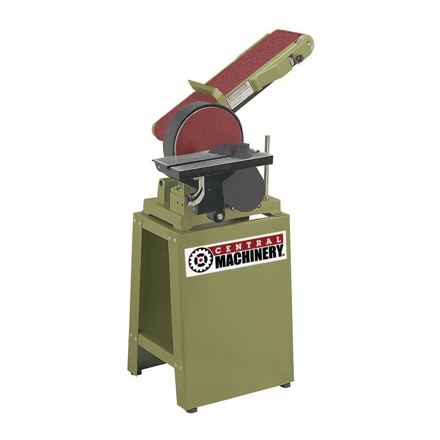
6" BELT & 9" SANDER
Visit our website at: http://www.harborfreight.com
Read this material before using this product.
Failure to do so can result in serious injury.
SAVE ThIS MANUAL.
Copyright
2004 by Harbor Freight Tools
©
contained herein may be reproduced in any shape or form without the express written consent of Harbor
Freight Tools. Diagrams within this manual may not be drawn proportionally. Due to continuing improvements,
actual product may differ slightly from the product described herein. Tools required for assembly and service
may not be included.
For technical questions or replacement parts, please call 1-800-444-3353.
Revised Manual 09k
ASSEMBLY AND OPERATING INSTRUCTIONS
. All rights reserved. No portion of this manual or any artwork
®
6852
Advertisement
Table of Contents

Related Manuals for Central Machinery Central Machinery 6" Belt & 9" Sander 6852


Summary of Contents for Central Machinery Central Machinery 6" Belt & 9" Sander 6852
- Page 1 Read this material before using this product. Failure to do so can result in serious injury. SAVE ThIS MANUAL. Copyright 2004 by Harbor Freight Tools . All rights reserved. No portion of this manual or any artwork © ® contained herein may be reproduced in any shape or form without the express written consent of Harbor Freight Tools.
-
Page 2: Product Specifications
PRODUCT SPECIFICATIONS Electrical Requirements 1 HP, Ball Bearing Motor 110 Volt/60 Hz/12.8 Amps 3450 Rpm Overall Height 40” Table Surface Dimensions 6-1/2” x 12-3/4” Table Tilt 0-50 Degrees Work Table Options For Sanding Disc or Sanding Belt Belt Size 6” x 48” Disc Size 9”... - Page 3 REPLACEMENT PARTS AND ACCESSORIES: When servicing, use only identi- cal replacement parts. Only use accessories intended for use with this product. Approved accessories are available from Harbor Freight Tools. MAINTAIN ThIS PRODUCT WITh CARE. Keep this product clean and dry for better and safer performance.
- Page 4 SPECIFIC PRODUCT WARNINGS AND PRECAUTIONS MAINTAIN A SAFE WORKING ENVIRONMENT. Keep the work area well lit. Make sure there is adequate surrounding workspace. Always keep the work area free of obstructions, sawdust, grease, oil, trash, and other debris. Do not use the Belt/Disc Sander in areas near flammable chemicals, dusts, and vapors.
- Page 5 ALLOW ThE SANDING BELT/DISC (2, 15) TO TURN UP TO FULL SPEED BEFORE FEEDING A WORKPIECE INTO ThE SANDING BELT/DISC. When turning off the Belt/Disc Sander, allow the Sanding Belt/Disc to slow down and stop on its own. Do not press against the Sanding Belt/Disc to stop it. FEED ThE WORKPIECE INTO ThE SANDING BELT/DISC (2, 15) GRADU- ALLY.
- Page 6 When unpacking, check to make sure all the parts shown on the Parts List on page 16 are included. If any parts are missing or broken, please call Harbor Freight Tools at the number shown on the cover of this manual as soon as possible.
-
Page 7: Assembly Instructions
ASSEMBLY INSTRUCTIONS NOTE: For additional references to the parts listed below, refer to the Assembly Diagram on page 17. To Assemble The Stands, Frames, And Upper Bracket: With assistance, position the two Stands (56) upright on the floor and parallel to one another. - Page 8 With assistance, carefully tip the assembled Stand on its side. Attach a Rubber Foot (59) to each of the Stand’s four corners, using four Rubber Feet, four Wash- ers (60), and four Screws (61). Then, place the Stand back in its upright position. (See Figure D.) To Attach The Base To The Upper Bracket: With assistance, place the Base (51) of the Belt/Disc Sander on top of the Upper...
- Page 9 To Assemble The Pulleys, Sanding Disc Plate, and Table: Remove the 4 screws from the cover on the Pulley Cover (22) and set aside. Line up the three bolt holes on the Pulley Cover FIGURE E (22) with the threaded holes in the Bracket (26).
-
Page 10: Operating Instructions
Remove the paper backing on the adhesive Sanding Disc (15), and stick the Sanding Disc firmly and evenly onto the Sanding Disc Plate (16). (See Figure I, page 11.) Replace cover of the Pulley Cover (22) and tighten the 4 screws. Verify that the pulley cover does not contact the Sanding Disc (15). -
Page 11: Table Of Contents
turn off the machine and unplug it from its electrical outlet. Then repeat Steps #2 through #7 to further increase the tension on the Sanding Belt. (See Figures B and h.) Attach the Back Stop (39) to the side of the Sanding Belt Frame (40), as shown in Figure h. - Page 12 To Adjust The Angle Of The Table: The angle of the Table (1) may be adjusted from 0 to 45 Degrees. (See Figure J.) To adjust the angle of the Table (1), slightly loosen the Knob (10). (See Figure J.) Observe the Angle Gauge (5).
- Page 13 MITER GAUGE MITER GAUGE KNOB ANGLE SCALE FIGURE K To Adjust The Sand Belt Frame For Vertical Sanding: Loosen the two Nuts (36) on the Sanding Belt Frame (40), and with assistance raise the Sanding Belt Frame to its full vertical position. Then, firmly retighten the two Nuts to lock the Sanding Belt Frame in place.
-
Page 14: Sanding Belt
4. NOTE: When repositioning SANDING BELT FRAME the Table (1), (40) make sure there END VIEW SIDE TABLE (1) is more than VIEW SANDING ” clearance BELT but less than ” TABLE clearance be- tween the Table and the Sand- ing Belt Frame SUPPORT BAR (40). - Page 15 To Perform Horizontal Sanding With The Sanding Disc: CAUTION: Before each use, inspect the condition of the Sanding Disc (15). Look for tearing, excessive wear, or other damage to the Sanding Disc. Never use a Sanding Disc that is damaged. When replacing, never use an inexpensive, low quality Sanding Disc.
-
Page 16: Caution: Always Turn The Power Switch
Once the sanding procedure is completed, remove the workpiece from the Sand- ing Belt (2), turn the Power Switch (53) to its “OFF” position, and unplug the Power Cord (55) from its electrical outlet. (See Figure B.) INSPECTION, MAINTENANCE, AND CLEANING CAUTION: Always turn the Power Switch (53) to its “OFF”... -
Page 17: Back Stop
PARTS LIST PART # DESCRIPTION QTY PART # DESCRIPTION Table Set Screw Sanding Belt Driving Roller Miter Gauge Nut (M8) Screw (M5x30) Key (B5x50) Angle Gauge Driving Roller Shaft Washer (8) Back Stop Screw (M8x12) Sanding Belt Frame Nut (M5) Roller Adjust Bar Table Support Bracket Spring Pin (5) -
Page 18: Assembly Diagram
ASSEMBLY DIAGRAM 35 33 41 42 31 21 NOTE: Some parts are listed and shown for illustration purposes only, and are not avail- able individually as replacement parts. REV 05b For technical questions, please call 1-800-444-3353. SKU 06852 PAGE 18... - Page 19 LIMITED 1 YEAR / 90 DAY WARRANTY Harbor Freight Tools Co. makes every effort to assure that its products meet high quality and durability standards, and warrants to the original purchaser that for a period of ninety days from date of purchase that the engine/motor, the belts (if so equipped), and the blades (if so equipped) are free of defects in materials and workmanship.