Table of Contents
Advertisement
Advertisement
Table of Contents

Related Manuals for Oki ML280 Elite


Summary of Contents for Oki ML280 Elite
- Page 1 ML280 ELITE user's guide...
- Page 2 The most up-to-date drivers and manuals are available from the Oki Europe website: http://www.okieurope.com Copyright © 2008. All rights reserved.
-
Page 3: Table Of Contents
CONTENTS Introduction ........6 Using this Manual . - Page 4 Index ......... . 49 Oki contact details ....... 51...
- Page 5 NOTES, CAUTIONS AND WARNINGS CAUTION! A caution appears in this manual like this. A caution provides additional information which, if ignored, may result in equipment malfunction or damage. WARNING! A warning appears in this manual like this. A warning provides additional information which, if ignored, may result in a risk of personal injury.
-
Page 6: Introduction
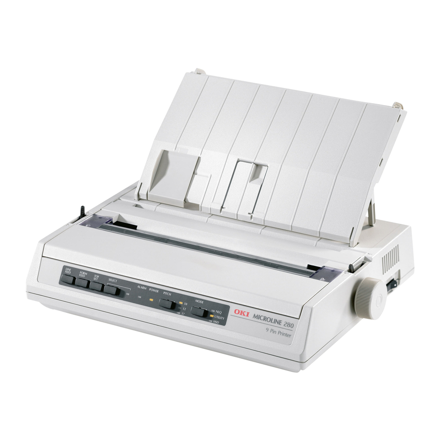
User’s Guide to get the most from your printer. The ML280 Elite is an entry level 9 pin dot-matrix printer. It is fast, robust, compact and light. Outstanding reliability, compact size and... -
Page 7: Online Usage
NLINE USAGE This manual is intended to be read on screen using Adobe Acrobat Reader. Use the navigation and viewing tools provided in Acrobat. You can access specific information in two ways: In the list of bookmarks down the left hand side of your screen, click on the topic of interest to jump to the required topic. - Page 8 Pages from and to for the range of pages you specify by entering their page numbers. Click on OK. INTRODUCTION > 8...
-
Page 9: Getting Started
GETTING STARTED OCATION Select a firm, solid surface on which to site your printer. Allow enough space around the printer to easily access the platen knob and the various paper feed paths. Make sure a suitable grounded power outlet is available nearby. -
Page 10: Removing The Shipping Restraint
Do not plug the printer into the AC supply until the following steps have been completed: EMOVING THE SHIPPING RESTRAINT Remove any packing tape. Insert your hand in the top cover slot (2) and remove the access cover (1) by lifting it. Remove the printhead shipping restraint. -
Page 11: Installing/Replacing The Ribbon Cartridge
NSTALLING EPLACING THE IBBON ARTRIDGE CAUTION! When replacing a Ribbon Cartridge, make sure you have the correct replacement ribbon for your printer. The wrong ribbon will not print when installed in your printer. IBBON ARTRIDGE ANDLING Leave unused ribbon cartridges in their packages until needed. - Page 12 When replacing a Ribbon Cartridge, first remove the old one. WARNING! If you are replacing the ribbon Cartridge, the printhead may be HOT! Unpack the ribbon cartridge and install it on the printhead. GETTING STARTED > 12...
-
Page 13: Installing The Platen Knob
Press gently on the ribbon cartridge until you feel it click into place. CAUTION! Do not remove the ribbon shield (“X” in graphic above) from the ribbon! Turn the take-up knob (a) in the direction of the moulded arrow to take up any ribbon slack. Replace the access cover. -
Page 14: Adjusting The Head Gap
DJUSTING THE The head gap is the distance between the print head and the platen roller. When you use envelopes or multi-part forms you will need to have a larger gap than when using plain paper. Use the recommended head gap to ensure the best print quality and easy paper feed. CAUTION! Incorrect setting of the print head gap can cause print head damage or ribbon jams. -
Page 15: Fitting The Paper Separator
ITTING THE APER EPARATOR The Paper Separator is utilised when using single sheets (no carbons) and when using continuous stationery to separate the ingoing/ outgoing paper to prevent paper jams. It is fitted as follows: Grasp the paper separator by either side, with the spring loaded stays to the rear of the printer. -
Page 16: Setting Up Your Printer
SETTING UP YOUR PRINTER OWER ONNECTION Make sure both the printer and the computer are switched OFF. MODELS Plug the power cord into the back of the printer, then into a grounded AC outlet. Switch the Printer ON. MODELS With the printer switched OFF..Terminate the free ends of the power cord with connector(s) appropriate for connection to your DC voltage source. -
Page 17: Loading Paper
Plug the power cord into the back of the printer and lock by twisting the collar of the connector clockwise. Switch the Printer ON. OADING APER Three types of paper can be used with your printer: Single sheet (with or without the optional cut sheet feeder) Roll paper (use the correct rollpaper stand) Fan-fold paper (with or without the optional tractor feed unit) When using fan-fold paper, adjust the distance between the sprocket... - Page 18 Remove the Access cover (1). Move the Bail arm lever (2) (on the left-hand side of the printer) to the front of the machine to lift the Bail bar. Move the Paper lever (3) (on the right-hand side of the printer) to the front of the machine, to the fan-fold symbol.
- Page 19 Push the paper in just enough so that its sprocket holes engage the sprocket pins located on the platen ends. Turn the Platen knob (5) to advance the paper until it appears in front of the platen. Move the Bail arm lever (2)to the rear of the machine to lower the Bail bar.
-
Page 20: Bottom Feed Continuous Form Fan-Fold Paper
OTTOM FEED CONTINUOUS FORM FAN FOLD PAPER Ensure that the printer is switched OFF and the power supply lead removed. Place the printer on a slotted printer stand, carefully aligning the slot in the stand with the slot in the base of the printer. Place a box of fan-fold paper under the printer stand. -
Page 21: Top Feed Single Sheet Paper
OP FEED SINGLE SHEET PAPER Your printer can accommodate single sheets of 216mm width x 297 or 355mm length paper. Remove the Tractor Feed unit and any other accessories, then raise the Paper Separator into its upright position. Switch the printer ON. Move the Paper lever (1) (on the right-hand side of the printer) to the rear of the machine, to the Blank sheet of paper symbol. -
Page 22: Testing Your Printer
Hold down the LINE FEED button and turn the printer ON. The printer will begin its test print. To stop the test, press the SELECT button or turn the printer OFF. Typical test print: ML280 ELITE ME1 F/W XX.XX 42434401YR-00 XX.XX HSD 10CPI !ӣ$%^&*()0123456789:;<=>@aABCDEFGHIJKLMNOPQRSTUVWXYZ[\]abcdefghijklm... -
Page 23: Computer Connections
OMPUTER ONNECTIONS NOTE It is not recommended that you connect serial/USB and parallel cables to the printer simultaneously. For connection to a PC running Windows 98 or above (not Windows 95 upgraded to Windows 98) or Macintosh. The operation of a printer is not assured if a USB compatible device is connected concurrently with other USB compatible machines. -
Page 24: Usb Connection
USB C ONNECTION Requires a USB 1.1 cable, maximum length 19.7 ft. (5 m), not supplied. Printer has a USB series “B” receptacle. NOTES For connection to a PC running Windows 98 or above (not Windows 95 upgraded to Windows 98). The operation of a printer is not assured if a USB compatible device is connected concurrently with other USB-compatible machines. -
Page 25: Serial Connection
ERIAL ONNECTION The Serial Interface Board is an option on this printer and is supplied with installation and setup instructions. CAUTION! Make sure the printer and computer are both turned OFF. Switch both the computer and the printer OFF. Plug the cable into the serial ports of both your PC and printer and tighten the thumbscrews (1). -
Page 26: Printer Drivers
RIVERS Printer drivers enable your computer to communicate with the printer. As with most printer manufacturers, Oki creates printer drivers for use with popular types of software, such as Microsoft Windows operating systems, from Windows 95 onwards. Installing a printer driver is normally a simple process of making a selection within the software. -
Page 27: Operating Your Printer
OPERATING YOUR PRINTER RONT ANEL PERATION LINE FORM SELECT POWER PITCH ALARM FEED FEED MODE UTILITY The Front Panel has 9 indicators and 6 buttons. The function of each is as follows: Indicators SELECT Lit - Printer ON-LINE, unlit printer OFF-LINE. Flashes with ALARM on to indicate a fault has been detected. - Page 28 Additional button functions if pressed at Power ON LINE FEED Initiates the printer self test. SELECT and Initiates the printer’s continuous rolling ASCII test. LINE FEED SELECT and Places the printer into a Hex dump mode, printing all data and control FORM FEED commands received as HEX codes for fault finding.
-
Page 29: Setting Printer Defaults
ETTING RINTER EFAULTS The printer has an internal MENU containing a number of default conditions that can be set to enable your printer to match the parameters required by your computer. MENU NTERING THE MODE Power on the printer while holding down the SELECT button. The 12 and UTILITY LEDs will flash. -
Page 30: Default Menu Selections
EFAULT ENU SELECTIONS Group Item Setting Printer Control See the Printer Driver section of this document for more information. Font Print Mode Utility Draft Mode Pitch 10 CPI Proportional Spacing Style Normal Size Single Symbol Sets Character Set Set II Language Set ASCII Zero Character... -
Page 31: Using The Pull Tractor Unit (If Fitted)
SING THE PULL RACTOR IF FITTED Paper can be loaded either from the rear of the printer or from the bottom if you have a slotted printer stand. Remove the access cover. Adjust the left tractor if necessary, making sure that it is not more than 12.7mm (0.5 inch) from the left-hand end of the tractor unit. - Page 32 Pull the paper under the Bail bar and up to the level of the tractor unit. Open the sprocket covers and slide the paper release lever forward. Locate the sprocket holes in the paper over the sprockets on the tractor unit and close both sprocket covers (leave the paper release lever open).
-
Page 33: Using The Cut-Sheet Feeder (If Fitted)
SING THE SHEET EEDER IF FITTED Paper set lever Left paper guide Rear sheet support Front sheet support Right paper guide Front sheet guide Place the paper set lever (1) in the RESET position. Release the paper guides by pushing the locking levers downward. -
Page 34: Manual Loading With The Cut-Sheet Feeder
Insert the paper stack into the hopper and push it against the left paper guide, making sure that the paper fits under the corner separators. Adjust the right paper guide to the paper width. Push both paper guide locking levers upward into the locked position. -
Page 35: Cut-Sheet Feeder Controls
SHEET EEDER CONTROLS The printer’s control switches also control the operation of the cut- sheet feeder. The control switches, however, function only when the printer is off-line or deselected (SELECT indicator is not lit). SING THE APER TAND IF FITTED OADING THE APER Open the paper separator all the way. - Page 36 Feed the paper down behind the platen and use platen knob to bring paper through the printer. Lift the bail arm as paper comes round to front of platen. (The paper release lever needs to be in the top position to perform this step).
-
Page 37: Maintenance
MAINTENANCE EPLACING THE IBBON ARTRIDGE “Installing/Replacing the Ribbon Cartridge’’on page 11 DJUSTING THE RINTHEAD “Adjusting the Head Gap’’on page 14 OADING APER “Loading Paper’’on page 17 ESTING YOUR PRINTER “Testing your printer’’on page 22 MAINTENANCE > 37... -
Page 38: Troubleshooting
> Is the paper properly installed? > Is the ribbon properly installed? > Is an Oki ribbon being used? > Is the printhead gap correctly set? > Are the correct printer drivers being used for the printer? NOTE >... - Page 39 The initialization string contains codes that override the panel and menu settings. To change your printer to ignore the reset code, enter the Menu Mode, go to the Set-Up group and change the setting for Reset Inhibit to Yes. The I-Prime signal will automatically override any front panel settings you have made.
- Page 40 Check to be sure that the printer driver you have selected in your software matches the printer emulation. Please refer to the Printer Driver section for details of emulations, then check the menu settings (see “Setting Printer Defaults” in the Operating your Printer section). If you have embedded any printer commands in your software, check to be sure that you entered them correctly.
- Page 41 Solution The head gap may not be set correctly. Try moving the headgap lever to a lower setting. If that doesn’t help, the printhead may be damaged; call for service. Problem The ALARM light is flashing. Solution Try turning the printer OFF and then back ON again. If the light still blinks, call for service.
-
Page 42: Clearing Paper Jams
LEARING APER Rear Feed Jams Turn the printer OFF. Use the platen knob to back the paper all the way out of the printer. CAUTION! Make sure the printer is turned OFF before you open the access cover. WARNING! The printhead may be HOT! Open the access cover, move the bail arm lever toward the front of the printer and remove any torn paper. -
Page 43: Rear Feed, Repeating Paper Jams
Rear Feed, Repeating Paper Jams If the paper keeps jamming, you may have: > defective paper > misaligned paper > bits of paper in the paper path Defective Paper Replace the defective paper with a fresh stack. Misaligned Paper Turn the printer OFF. Use the platen knob to back the paper all the way out of the printer. -
Page 44: Single Sheet Paper Jams
Single Sheet Paper Jams Turn off the printer. Use the platen knob to back the paper out. Open the access cover. Remove any torn pieces from around the carriage. Close the access cover. > 44... -
Page 45: Parts And Accessories
Item descriptions and part numbers are provided in this section. Consult the dealer where you purchased your printer. Locate an Authorised Oki Data Reseller by visiting your local Oki web site. Links to all countries are provided on: http://www.okieurope.com... -
Page 46: Options
OPTIONS Option Part number Pull Tractor Assembly (1) 09002363 Roll Paper Stand (2) 09002334 Cut Sheet Feeder (3) 09000689 Serial Interface Card, RS232 (4) 09002353 Serial Interface Card, RS422 (not shown) 09002357 Current Loop Interface Card (not shown) 09000685 All Accessories are supplied complete with an Installation Guide. PARTS AND ACCESSORIES >... -
Page 47: Specifications
Print Method Impact dot matrix Printhead 9 pins, 0.30 mm (0.0118") diameter, with thermal protection Emulations (co-resident) Epson FX IBM Graphics Oki MICROLINE Print Speed High Speed Draft (HSD) 333cps* Utility (UTL) 250cps* Near Letter Quality (NLQ) 62.5cps* * cps = characters per second... - Page 48 Item Specification Temperature Operating 5 to 40°C Storage -40 to +70°C) Humidity Operating 20 to 80% RH Storage 5 to 95% RH Interfaces: Standard: Centronics parallel, IEEE-1284 compliant USB 1.1 Optional: RS-232C Serial RS-422 Current Loop SPECIFICATIONS > 48...
-
Page 49: Index
INDEX Front Panel .........27 Access cover......18 Additional button functions if Graphics........30 pressed at Power ON....28 ALARM........27 Auto CR ........30 Humidity........48 Auto LF ........30 Auto Select .........30 Impact Mode.......30 Initialization string......38 Bail arm lever....... 18 Installing the Ribbon Cartridge ..11 Bi - Direction.......30 I-Prime ........ - Page 50 Paper Specifications ....47 SELECT ........27 Parallel (LPT) Connection.....23 SELECT and FORM FEED ....28 Parallel Interface SELECT and LINE FEED ....28 I-PRIME Signal ......38 Serial Cable Connection ....25 Pin 18.........30 Serial Interface Option ....39 PITCH .........27 Setting Printer Defaults ....29 POWER ........27 Skip Over Perforation ....30 Power Connection ....
-
Page 51: Oki Contact Details
Fax : (64) 9 477 0549 Tel : (81) 3 5445 6158 http://www.comworth.co.nz Fax : (81) 3 5445 6189 http://www.okidata.co.jp Oki Data (S) P Ltd. Malaysia Rep Office Oki Data (Singapore) Pte. Ltd. Suite 21.03, 21st Floor Menara IGB, 78 Shenton Way, #09-01,... - Page 52 ML280 ELITE Blays House Wick Road, Egham Surrey, TW20 0HJ United Kingdom tel +44 (0) 20 8219 2190 Fax +44 (0) 20 8219 2199 07051001 ISS.02...