
Related Manuals for A&D FC-5000Si


Summary of Contents for A&D FC-5000Si
-
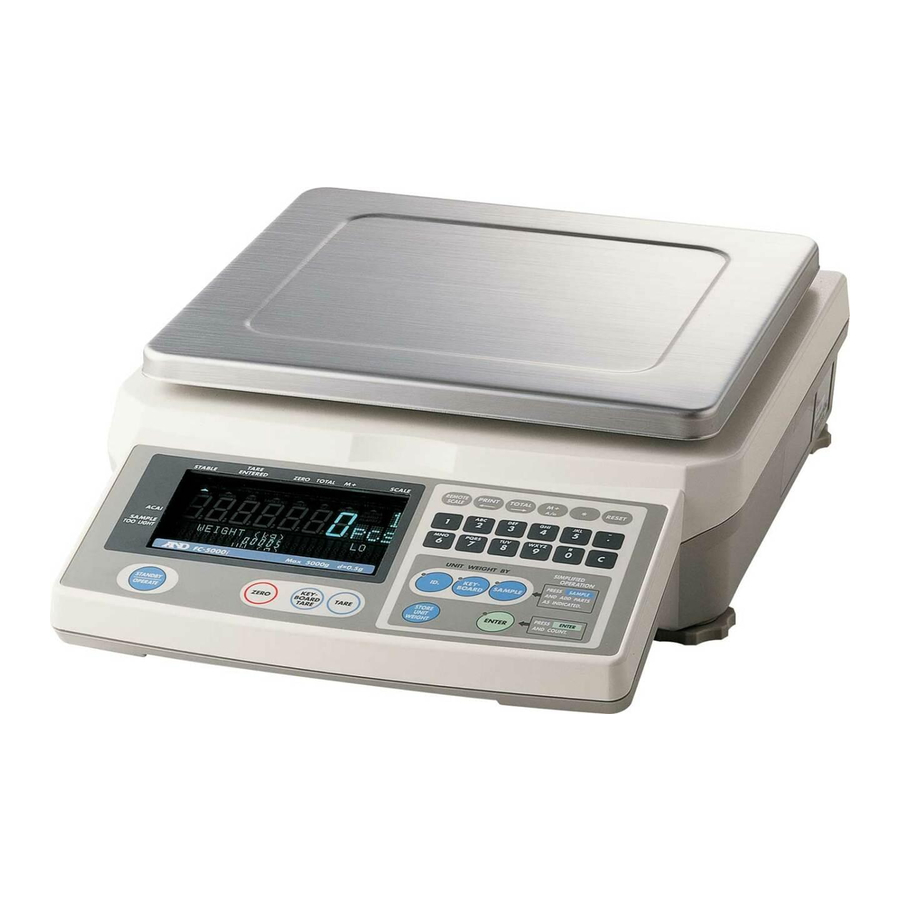
Page 1: Counting Scale
ふ Counting Scale FC-50Ki FC-5000Si FC-20Ki FC-500Si FC-10Ki FC-5000i FC-2000i FC-1000i FC-500i WM+PD4000541B... -
Page 2: Compliance With Fcc Rules
This manual and Marks All safety messages are identified by the following, “WARNING” or “CAUTION”, of ANSI Z535.4 (American National Standard Institute: Product Safety Signs and Labels). The meanings are as follows: A potentially hazardous situation which, if not avoided, could result WARNING in death or serious injury. -
Page 3: Table Of Contents
Contents 1. INTRODUCTION ......................3 1-1. Introduction..........................3 1-2. Unpacking ..........................4 1-3. Setting Up Your Scale ......................5 1-4. Standby and Operating Mode....................7 1-5. Simple Operation Mode......................7 1-6. kg or lb Weighing Units ......................7 1-7. Last Unit Weight Used Feature ....................8 2. - Page 4 9-1. Calibration Procedure Using a Weight .................. 31 9-2. Gravity Compensation......................33 10. F-FUNCTION PARAMETERS..................34 10-1. To Change or View F-Function Settings................34 10-2. F-Functions ........................36 11. ACAI FUNCTION .......................44 11-1. ACAI Automatic Counting Accuracy Improvement ............44 11-2. ACAI Automatic Operation ....................
-
Page 5: Introduction
1. INTRODUCTION 1-1. Introduction Thank you for your Purchase! This manual describes the functions of your counting scale and how to get the most out of it. Read this manual carefully before use. Features The FC-i / FC-Si counting scales have the following features: The scales have the following high internal resolution for a wider range of counting applications. -
Page 6: Unpacking
AC adapter type is correct for your local voltage and Remove Packing Material receptacle type. How to assemble the breeze break (Only for FC-500Si) Assemble the breeze break as FC-1000i shown below. Follow the numbered FC-500i sequence. Breeze ring Only for FC-5000Si FC-5000Si FC-500Si... -
Page 7: Setting Up Your Scale
1-3. Setting Up Your Scale 1. Place the scale on a suitable weighing surface (Refer to Best Conditions For Weighing of next page) and turn the adjustable feet until the spirit level shows that the scale is level. RS-232C AC adapter jack Weighing pan OP-02 slot Spirit level... - Page 8 Best operating temperature is between 20°C~25°C / 68°F~77°F at about 50%~60% relative humidity. There shouldn’t be large temperature fluctuations. The weighing room should be kept clean and dry. The weighing table must be of a solid construction. Corners of rooms are best as they are less prone to vibrations. Don’t install the scale near heaters or air conditioners.
-
Page 9: Standby And Operating Mode
1-4. Standby and Operating Mode The scale has two principal modes: Standby mode and operating mode. Standby mode: When the scale has power supplied to it, either by the AC Adapter or the battery pack, and the display shows a decimal point, the scale is in the standby mode. -
Page 10: Last Unit Weight Used Feature
1-7. Last Unit Weight Used Feature There are a number of ways to register a unit weight to count. The scale has a feature to keep the last unit weight used in memory. This can be handy if you turn the scale display off and then want to return to the same unit weight, or you accidentally clear the unit weight by pressing the RESET key. -
Page 11: Front Panel Overview
2. FRONT PANEL OVERVIEW... -
Page 12: Basic Operations
3. BASIC OPERATIONS 3-1. Basic Operations Turn The Display ON and OFF TARE ZERO SCALE STABL TOTAL ENTERED 888888. 1. Press the STANDBY/OPERATE key to turn the scale on when displaying the standby indicator. The display will show all the 8 8 8 8 8 8 8 8 8 8 8 8 8 8 8 8 8 8 8 8 8 8 8 8 8 8 8 display segments... - Page 13 TARE TARE The TARE key will subtract the displayed ZERO SCALE STABL TOTAL ENTERED container weight. 888810 1. Remove everything from the weighing pan and W E I G H T ( k g ) press the ZERO key to zero the scale. 12134567890 .
-
Page 14: To Start Counting
3-2. To Start Counting 1. Press the STANDBY/OPERATE key to turn the scale on when displaying the standby indicator. Or press the RESET key to clear TARE ZERO STABL TOTAL SCALE ENTERED any previous operations. 888810 2. Three LED’s on the UNIT WEIGHT BY keys W E I G H T ( k g ) 12134567890 . -
Page 15: Unit Weight By Samples
3-3. Unit Weight By Samples 10 Sample Size 1. Three UNIT WEIGHT BY LED’s should be blinking at this point, if not, press the RESET key to clear any unit weight. lf you are going to use a tare container, place it on the weighing pan. - Page 16 5, 25, 50 or 100 Sample Size 1. Three UNIT WEIGHT BY LED’s should be blinking at this point, if not, press the RESET key to clear any unit weight. lf you are going to use a tare container, place it on the weighing pan.
- Page 17 Desired Sample Size 1. Three UNIT WEIGHT BY LED’s should be blinking at this point, if not, press the RESET key to clear any unit weight. lf you are going to use a tare container, place it on the weighing pan.
- Page 18 Desired Sample Size Not Using The SAMPLE 1. Three UNIT WEIGHT BY LED’s should be blinking at this point, if not, press the RESET key to clear any unit weight. lf you are going to use a tare container, place it on the weighing pan and press the TARE key.
-
Page 19: Unit Weight By Keyboard
3-4. Unit Weight By KEYBOARD 1. Three UNIT WEIGHT BY LED’s should be blinking at this point, if not, press the RESET key to clear any unit weight. lf you are going to use a tare container, place it on the weighing pan and press the TARE key TARE to tare the container. -
Page 20: Unit Weight By Id Number
3-5. Unit Weight By ID Number 1. If there are no unit weight’s stored in memory, refer to “5-1. Store Unit Weight by ID Number”. Three UNIT WEIGHT BY LED’s should be blinking at this point, if not, press the RESET key to clear any unit weight. -
Page 21: Entering A Tare Weight
4. ENTERING A TARE WEIGHT There are two methods of tare operations. Using the TARE key to subtract the displayed container weight directly. Please refer to “3-1. Basic Operations”. Using the KEYBOARD TARE key to enter a tare weight via the 10-key pad. 4-1. -
Page 22: To Clear Tare
4-2. To Clear TARE TARE Either: ZERO STABL SCALE TOTAL ENTERED 88-554 1. Have nothing on the weighing pan. If the ZERO indicator is not displayed, press the ZERO key to zero the scale. 2 A A W E I G H T ( k g ) 1234105678-0 . -
Page 23: Store Unit Weight
5. STORE UNIT WEIGHT 5-1. Store Unit Weight by ID Number The scale can store up to 500 unit weights by 6 digit ID numbers, from 000001 to 999999. To recall, refer to “3-5. Unit Weight By ID Number”. The scale is initially set to store the ID numbers with a unit weight and an item code only. -
Page 24: Clearing A Stored Unit Weight
5-2. Clearing A Stored Unit Weight 1. Press and hold the C key, then press STORE UNIT the STORE UNIT WEIGHT key – release both. WEIGHT Clear ID 2. “ ” will appear and “id-000000” 888810 000000 will appear with blinking. -
Page 25: Store Item Code By Id Number
5-3. Store Item Code by ID Number An item code of up to 12 alphanumeric characters can be set using the 10-key pad, and it will be stored with the ID number. 1. Press the STORE UNIT WEIGHT 888810 key. “id-000000” will appear with 000000 blinking. - Page 26 ----10 11. Press the ENTER key. The ID number is stored with Item code and the display returns W E I G H T ( k g ) ENTER 123516-1--1 . 1 1056 8id-123456 to normal. 2 3 S 1 A A U U W ( g ) A &...
-
Page 27: Unit Weight, Tare, Comparator Limits & Total Count Stored
5-4. Unit Weight, Tare, Comparator Limits & Total Count Stored The scale is initially set to store the ID numbers with a unit weight and an item code only. However, it can be set to store a tare weight, comparator limits and/or total count also by setting F-Function f-01-05. -
Page 28: Using The M+ Memory
6. USING THE M+ MEMORY 6-1. The M+ Memory Function The scale can accumulate count data by pressing the M+ key, or automatically (refer to the next page). It also keeps track of the number of times you add to the total. -
Page 29: Viewing The M+ Total
2. The scale will clear the last M+ addition. If the scale beeps 4 times, there is no M+ addition to erase. Automatic M+ Accumulation Mode M+ Accumulation can also be done automatically each time you count a different batch, As soon as you have a stable count, it will be added to the M+ memory and the scale will beep . -
Page 30: Comparator Function
This function is not to clear the last M+ addition, but to subtract count data instead of addition. The number of additions is increased. There is no automatic M- function. 7. COMPARATOR FUNCTION The scale contains a comparator function that checks the amount on the weighing pan against set acceptable count or weight 88-100 levels. - Page 31 The count display will show the F-Function and its present setting will blink. 4. Use the 0 6 keys to display the . f -05-01 number of the desired setting. For example, let’s select “1” compare all C o m p a r a t o r 12345678C000045678id-000001 data.
-
Page 32: Time And Date Function
These temporary limits will disappear when the display is turned off. 8. TIME AND DATE FUNCTION The scale has a time and date function and that data can be sent through the RS-232C interface. There are two ways to set time and date. To Set in the F-Function Settings Start with the scale in standby mode, with the display is turned off. -
Page 33: Calibration
4. Use the 10-key pad to set the time and press the ENTER key to return to normal. The clock will start from “00” seconds. 9. CALIBRATION Calibration of the scale is required when it is initially installed, if it is moved often, or it is moved a substantial distance. - Page 34 display the desired calibration weight. (For example: Using 10kg calibration weight that actually weighs 10.002kg.) 3. Press the ENTER key. 8 Call00 The calibration weight stops blinking and “Cal 0” appears. C a l i b r a t i o n Z e r o ENTER Cala0 C a l i b r a t i o n w e i g h t ( k g )
-
Page 35: Gravity Compensation
9-2. Gravity Compensation When the scale is first used or has been moved to different place, it should be calibrated using a calibration weight. But if the calibration weight cannot be prepared, the gravity acceleration correction will compensate the scale. Change the gravity acceleration value of the scale to the value of the area where it will be used. -
Page 36: F-Function Parameters
10. F-FUNCTION PARAMETERS 10-1. To Change or View F-Function Settings Start with the scale in standby mode, with the display is turned off. 1. Press and hold the ZERO key, then press STANDBY the STANDBY/OPERATE key. ZERO OPERAT The count display will show “f-00” with -000 “00”... - Page 37 6. Press the ENTER key to . f -05-02 save any changes and/or move to the next item. C o m p a r a t o r ENTER 12345678C000045678id-00000 2 3 S A M U U W ( g ) 1 2 C l e a r I D 12345670 .
-
Page 38: F-Functions
10-2. F-Functions “ ” designates factory settings. F-00-X Weighing Unit USA Version ONLY Weight Display. f-00-01 kg (kilograms, FC-i series), g (grams, FC-Si series) 3 lb (pounds). Unit Weight (when “lb” is selected). f-00-02 lb as piece weight. 3 lb as 1,000 piece weight. F-01-X Operations Operation Mode. - Page 39 Display ON Unit Weight – Reset or Last. When the display is turned on, the scale can be set to recall f-01-04 the last unit weight used. 3 The unit weight is RESET (cleared) when display comes on. The unit weight last used (before display is turned off, not power interrupt) will be entered automatically.
- Page 40 F-02-X ACAI Operation & Min. Unit Weight ACAI Mode When Unit Weight Entered by Sample Pieces. f-02-01 ACAI is disabled. 3 ACAI automatic operation. ACAI manual mode (using the ENTER key). ACAI Mode When Unit Weight Entered by Keyboard or ID f-02-02 ACAI is disabled.
- Page 41 F-04-X Environment and Beeper Zero Tracking. Zero tracking traces a drift from zero caused by temperature f-04-01 changes etc., and stabilizes the zero point. 3 Zero tracking ON. Zero tracking OFF. Response f-04-02 Fast / sensitive 3 Normal Slow / stable Stable Detection Speed / Environment f-04-03 Fast stable detection (good environment).
- Page 42 Upper Limit. f-05-03 Enter via the 10-key pad. Use the - or . key to “set minus value. Lower Limit. f-05-04 Enter via the 10-key pad. Use the - or . key to set minus value. A Beeper With Comparator Results. f-05-05 These are beeps for the comparator, not for the key operation.
- Page 43 Data to be Sent. 00100 f-X-02 3 Count data sent. Date/Time Unit You select which data to be sent by keying in a Weight 0 or 1 for the data: Date, ID no., PCS (count), weight or unit weight. 00000 Example: Key in 0 0 to display 01100, this setting would send only the ID...
- Page 44 F-09-X Operation mode for th f-09-01 Operating as a MODE key to display comparator upper and lower limits, and time and date. Operating as M- key to subtract Count data from M+ memory. Decimal Point and Weight Data for RS-232C Output f-09-02 Decimal point="...
- Page 45 F-11-X Time & Date Time and Date Display. Select the order of date display. f-11-01 Year-Month-Date. 3 Month-Date-Year. Date-Month-Year.
-
Page 46: Acai Function
11. ACAI FUNCTION 11-1. ACAI Automatic Counting Accuracy Improvement TARE The ACAI (Automatic Counting Accuracy ZERO STABL SCALE TOTAL ENTERED 888828 Improvement) function recalculates the unit weight as more pieces are added to improve count accuracy. W E I G H T ( k g ) ACAI 12134567893 . -
Page 47: Acai Manual Operation
Pcs On the ACAI Weighing Pan Addition Range 63~123 13~27 73~139 23~50 83~153 33~71 93~167 43~90 103~300 53~107 over 200 203~493 STABLE STABLE STABLE ACAI ACAI ACAI As you add, the ACAI When you stop adding After the new unit indicator will be ON and the display weight is calculated,... -
Page 48: Rs-232C Serial Interface
12. RS-232C SERIAL INTERFACE The scale has not only a standard RS-232C interface but also optional interfaces, Ch.1 and Ch.2. The specifications described in this section are common to all of the RS-232C interfaces. 12-1. RS-232C Specifications Transmission system EIA RS-232C Transmission form Asynchronous, bi-directional, half-duplex Data format... -
Page 49: Data Output Mode
12-2. Data Output Mode The data output modes and parameters are set by F-Functions in f-06 08-X as described in the F-Function parameters, section 9. To control the scale using commands from an external device, refer to “12-5. Command Mode”. Refer to “12-5. -
Page 50: Connecting The Ad-8121 Printer / Mode 1 Or Mode 2
Data Format (f-06/07/08-03) 08-03="0") Format for AD-8121 MODE 1 or 2. (f-06 08-03="1") Format for AD-8121 MODE 3. (f-06 08-03="2") Format for general apparatuses, computers, etc. (f-06 Baud Rate (f-06/07/08-04) Select the baud rate according to the device to be connected. 08-04="0") 2400 bps (f-06 Select 2400 bps to connect with an AD-8121. -
Page 51: Connecting The Ad-8121 Printer / Mode 3
12-4. Connecting the AD-8121 Printer / MODE 3 When using MODE 3 of the AD-8121 printer, printouts are obtained using the 08-01 = 0), or auto-print mode A/B (f-06 08-01 =2 or 3). PRINT key (f-06 MODE 3 can print the ID number with its item code. To print date/time, set f-06 08-02 at "1####"... -
Page 52: Command Mode
12-5. Command Mode In the command mode, the scale is controlled by commands that come from an external device, computer etc. Do not set f-06/07/08-01="1" (stream mode) to use with the command mode. if you don’t want to use command mode together with key mode or auto-print mode, set f-06/07/08-01="4"... - Page 53 Command Definition Notes Store the unit weight and tare weight into the specified ID memory. Store the item code into the specified ID memory. Refer to the data format for the reply. Store the comparator limits into the specified ID memory. Store the total count and number of additions into the specified ID memory.
-
Page 54: Data Format
Data Format “ ” in examples below shows “Space” (20H). Store the unit weight in use, other values (according to f-01-05) and specified item code Stores into id000123 with no item code. E , 1 2 3 C L Command Stores into id000123 with item code E , 1 2 3 , a b c C L "... - Page 55 A N , 0 0 0 0 1 2 3 4 C L Reply Tare weight ? T R C L Command k g C L Reply T R , + 0 0 1 . 2 3 4 6 Request the scale to reply with the contents of ID memory. Request the contents of id000123.
- Page 56 Store the comparator limits into a specified ID memory. M L , 1 2 3 , + 1 0 1 0 , + 9 9 0 C L Command ID # Upper Limit Lowe Limit Reply ID number: Maximum 6 digit Upper limit: Maximum 9 digit including sign Lower limit:...
-
Page 57: Using A Bar Code Reader
12-6. Using a Bar Code Reader The bar code reader can be connected to the RS-232C interface on the scale. It can read bar codes for the ID number, unit weight, tare weight and comparator limits. Any of the RS-232C interfaces can be used for the bar code reader. Set the F-Function f-06/07/08-01="5"... - Page 58 Read the instruction/technical manual of your bar code reader to connect it with the scale. Bar Code Data and Format The bar code data that the scale accepts are ID number, unit weight, tare weight and comparator limits. The bar code has "2 digit identification code + 6 digit numbers" for the ID number and "2 digit identification code + maximum 10 digit numbers including sign and decimal point"...
- Page 59 Enter a tare weight in “g” directly. Tare Weight 10 digits including sign Similar to “4-1. Using the and decimal point. KEYBOARD TARE key”. If the EAN/JAN/UPC-A is used for ID number, put leading zeros (that are “0” for the high-order digits) to keep the necessary digit number.
- Page 60 Comparator upper limit Codabar (NW-7) =12345 A17+000012345A...
-
Page 61: Using Ufc (Universal Flex Coms) Function
12-7. Using UFC (Universal Flex Coms) Function The UFC function allows you to print out as you format the printer (UFC format). The scale can store the UFC format as text data. It will include parameters to replace with the count data, weight data and so on. The maximum number of text data is 384 characters. - Page 62 Example: #04 “EOT” of ASCII code Repeat data The control codes $SP, $CR and $LF can be used with “ + maximum 2 digit number”. That code will be repeated the number of times designated. Example: $LF 9 Repeat “$LF” 9 times. $SP 12 Put 12 “Spaces”.
- Page 63 Examples of PF command and AD-8121 Printout Sample AD-8121 Printout “PF” Command (f-06/07/08-03=” 0” or “1”) PF,‘ID ’,$CD,$CR,$LF,& ID 000123 PN Z D 5.6V ‘PN ’,$NM,$CR,$LF,& Count ‘Count’,$CR,$LF,& +1234 PC $SP 4,$PC,$CR,$LF,& Unit Weight ‘Unit Weight’,$CR,$LF,& $SP 4,$UW,$CR,$LF,& +1.234567 Weight ‘Weight’,$CR,$LF,&...
-
Page 64: Options
13. OPTIONS 13-1. OP-01 Bar Code Reader The OP-01 includes a bar code reader, RS-232C cable, AC adapter (100V~240V), power plug adapter (US to European plug) and a setting-up bar code sheet. The OP-01 bar code reader can be connected to one of the RS-232C interfaces. It can read bar codes for the ID number, unit weight, tare weight and comparator limits. - Page 65 Using OP-01 Bar Code Reader 1. Plug the modular connector of RS-232C cable into the port on the bottom of bar code reader, and twist the lock to the right to lock it. 2. Connect the other end of the RS-232C cable to the RS-232C interface of the scale.
- Page 66 Disable transmitting UPC-E Step 6 check digit Disable transmitting EAN-13 Step 7 check digit Disable transmitting EAN-8 Step 8 check digit Disable transmitting CODABAR Start/Stop Step 9 character Disable transmitting CODE 39 Step 10 check digit Disable transmitting Step 11 Interleaved 2 of 5 check digit End of configuration Step 12...
-
Page 67: Ni-Mh Battery Pack
13-2. OP-02 Ni-MH Battery Pack Using OP-02 Battery Pack By using the OP-02 Ni-MH battery pack, the scale can be operated for around 10 hours, after a full charge and using no other options 1. After making sure that the battery switch on the battery pack is "OFF" position, insert the battery pack firmly into the rear side of the scale. - Page 68 2. Fully loosen the lock screw and remove the battery. If you want to recharge the battery while it is still in the scale, you may do so. In that case, disregard step 2 – but do not turn the battery switch on. If you wish to use the scale, connect another AC adapter.
-
Page 69: Ch. Rs-232C
13-3. OP-03 2 Ch. RS-232C Multiple RS-232C interfaces expanding your counting applications are obtained by installing OP-03. OP-03 Installation Standard RS-232C 1. Disconnect the AC adapter from the scale. 2. Remove the two screws and panel covering the OP-03/04 slot. 3. -
Page 70: Rs-232C And Comparator Relay Output
13-4. OP-04 RS-232C and Comparator Relay Output Multiple RS-232C interfaces and relay output for the comparator results are obtained by installing OP-04. OP-04 Installation See the OP-03 installation. OP-04 is installed to the same slot as option OP-03. The RS-232C specifications are same as the standard RS-232C interface. Refer to “12. -
Page 71: Remote Scale Interface
13-5. OP-05 Remote Scale Interface A two-scale system using the scale is possible by installing OP-05 and connecting a remote scale. You can use any load cell platform that meets the conditions in this section. OP-05 Installation 1. Disconnect the AC adapter from the scale. 2. - Page 72 Specifications for Remote Scale The scale has the ability of driving up to 4 load cells (350Ω) in a remote scale (platform). Set for the capacity range 0.5kg to 5,000kg (1 lb to 10,000 lb). The scale has the ability of driving up to 4 load cells (350Ω) in a remote scale (platform).
- Page 73 Step Parameters Example 1 Example 2 Example 3 200kg 30.0kg 600kg 20,000 30,000 60,000 d’ 2 (=0.02kg) 5 (=0.005kg) 10 (=0.1kg) Ns x d 20,000 x 2 30,000 x 5 6,000 x 1 1/No (=d/Ns) 1/10,000 1/6,000 1/6,000 6. Calculate the voltage sensitivity “Es”. Es = (As-Ao) x 5,000 x 1/No (µV) [5,000 means excitation voltage 5V] Ao: Load cell output at zero point (mV/V)
- Page 74 (kg) = 0.005 x 2/5 = 0.002 (kg) Ws (kg) = 0.002 (kg) x 6,000 = 12 (kg) Calibrating the Remote Scale When a remote scale is newly connected, set the capacity and calibrate the scale using a weight. The scale must be warmed up (plugged in) for at least 30 minutes before starting calibration.
-
Page 75: Specifications
6. Go to step 2 in section “9-1. Calibration Procedure Using a Weight” to calibrate the remote scale. 14. SPECIFICATIONS MODEL FC-500i FC-1000i FC-2000i FC-5000i FC-10Ki FC-20Ki FC-50Ki Capacity (k)g 500 g 1 kg 2 kg 5000 g 10 kg 20 kg 50 kg Resolution (k)g... - Page 76 MODEL FC-500Si FC-5000Si Capacity g 500 g 5000 g Resolution g 0.02 g 0.2 g Capacity lb 1 lb 10 lb Resolution lb 0.00005 lb 0.0005 lb Sample Size 10 pieces normal – 5, 25, 50, 100 or random number, user selectable Min.
-
Page 77: Dimensions
14-1. Dimensions FC–2000i FC–5000i FC–10Ki FC–20Ki FC–50Ki FC–500i FC-1000i FC–5000Si FC–500Si... -
Page 78: Gravity Acceleration Map
15. GRAVITY ACCELERATION MAP Values of gravity at various locations Amsterdam 9.813 m/s Manila 9.784 m/s Athens 9.807 m/s Melbourne 9.800 m/s Auckland, NZ 9.799 m/s Mexico City 9.779 m/s Bangkok 9.783 m/s Milan 9.806 m/s Birmingham 9.813 m/s New York 9.802 m/s Brussels 9.811 m/s... - Page 79 World map...
-
Page 80: Index
16. INDEX -------......10, 11, 13, 14, 15 Counting ..........12 key ........9, 27, 29, 42 Data format ......41, 46, 48, 52 ~ , Space code......52, 59, 60 Data length ...........41 ,Standby indicator ......7 Date and time ........47 Dimensions ........72, 73 AC adapter ........4, 5, 6 Display off ..........5 AC adapter jack ........5 Earth terminal .........5... - Page 81 Operating mode ......7, 36 Stable detection speed ......39 Simple operation........36 STABLE indicator ........9 Simple operation mode ......7 Standby indicator ......7, 10 Standby mode........7 STANDBY/OPERATE key ..5, 7, 9, 64 Stream mode ........47 Start bit ..........46 Net weight..........19 Stop bit ..........46 no id............18 STORE UNIT WEIGHT key ......
- Page 82 MEMO...
- Page 83 MEMO...
- Page 84 ------- ~ , Space code ,Standby indicator...