Table of Contents
Advertisement
[1]
U.S.A. ONLY) ......................................... . ....... 1-1
[2]
Specifications ................................. . ....... 1-1
[3]
Names Of Parts................................ . ....... 1-2
[1]
ADJUSTMENT ....................................... . ....... 2-1
[2]
Test Mode .......................................... . ....... 2-3
[3]
Standard Specification of Stereo System
Error Message Display Contents ........... . ....... 2-5
CHAPTER 3. MECHANICAL DESCRIPTION
[1]
REMOVING AND REINSTALLING THE
MAIN PARTS ......................................... . ....... 3-1
[2]
Disassembly ...................................... . ....... 3-3
CHAPTER 4. DIAGRAMS
[1]
Block Diagram ................................. . ....... 4-1
[1]
Waveforms Of Cd Circuit ............ . ....... 5-1
[2]
Voltage............................................... . ....... 5-2
SERVICE MANUAL
CONTENTS
SHARP CORPORATION
MICRO COMPONENT SYSTEM
XL-HP515
MODEL
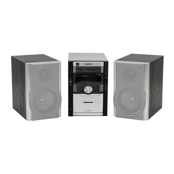
XL-HP515 Micro Component System consisting of XL-
HP515 (main unit) and CP-HP515 (speaker system).
• In the interests of user-safety the set should be restored to its origi-
nal condition and only parts identical to those specified be used.
CHAPTER 6. CIRCUIT SCHEMATICS AND PARTS
LAYOUT
[1]
Notes On Schematic Diagram ............6-1
[2]
Types Of Transistor And Led ............6-1
[3]
WIRING SIDE OF PWB/SCHEMATIC DIA-
GRAM............................................................6-2
CHAPTER 7. FLOWCHART
[1]
Troubleshooting ..................................7-1
[1]
Function Table Of Ic .............................8-1
[2]
Fl Display ................................................ 8-11
This document has been published to be used
for after sales service only.
The contents are subject to change without notice.
XL-HP515
No. S4422XLHP515U
Advertisement
Table of Contents

Related Manuals for Sharp XL-HP515


Summary of Contents for Sharp XL-HP515
- Page 1 MICRO COMPONENT SYSTEM XL-HP515 MODEL XL-HP515 Micro Component System consisting of XL- HP515 (main unit) and CP-HP515 (speaker system). • In the interests of user-safety the set should be restored to its origi- nal condition and only parts identical to those specified be used.
-
Page 2: Specifications
XL-HP515 Audio XL-HP515 Service Manual XLHP515 Market CHAPTER 1. GENERAL DESCRIPTION FOR A COMPLETE DESCRIPTION OF THE OPERATION OF THIS UNIT, PLEASE REFER TO THE OPERATION MANUAL. [1] IMPORTANT SERVICE NOTES (FOR U.S.A. ONLY) BEFORE RETURNING THE AUDIO PRODUCT (Fire & Shock Hazard) -
Page 3: Names Of Parts
XL-HP515 [3] NAMES OF PARTS Front panel 1. Disc Trays 2. Timer Indicator 3. Power On/Stand-by Button 4. Clock/Timer Button 5. CD Track Down or Fast Reverse, Tape Fast Wind, Tuner Preset Down, Time Down Button 6. Tape Reverse Play Button 7. - Page 4 XL-HP515 I Remote control 1. Remote Control Transmitter 2. Disc Number Select Buttons 3. CD Track Down or Fast Reverse, Tape Fast Wind, Tuner Preset Down, Time Down Button 4. Volume Up and Down Buttons 5. Disc Direct Search Buttons 6.
- Page 5 XL-HP515 Audio XL-HP515 Service Manual XLHP515 Market CHAPTER 2. ADJUSTMENTS [1] ADJUSTMENT • Tape Speed 1. MECHANISM SECTION Test Tape Adjusting Specified Instrument Point Value Connection • Driving Force Check Normal MTT-111 Variable 3,000 ± 30 Hz Speaker Ter- Torque Meter...
- Page 6 XL-HP515 2) Tracking balance adjustment 3) Gain adjustment (The gain is compensated inside the IC so that the loop gain at the gain crossover frequency will be 0 dB.) * Focus gain adjustment * Tracking gain adjustment 4. CD ERROR CODE DESCRIPTION...
-
Page 7: Test Mode
XL-HP515 [2] TEST MODE • Setting the test mode During stand-by mode, press ON/STAND-BY button while pressing down the button and X-BASS/DEMO button. then, press the CD button to enter the test mode. T E S T IL isn’t done OPEN/CLOSE operation is using manual. - Page 8 XL-HP515 <<MEMORY>> key input. Laser ON. <<MEMORY>> key input. Tracking OFF play at that specific point. <<MEMORY>> key input. Tracking ON play from that specific point. <<MEMORY>> key input. Adjustment result automatically will display as below for each 2 sec : a) "FOF_XXXX"...
-
Page 9: Standard Specification Of Stereo System Error Message Display Contents
XL-HP515 [3] Standard Specification of Stereo System Error Message Display Contents Error Contents DISPLAY Notes Pickup Mechanism Error. 'ER-CD01' PU-IN SW Detection NG. CD Changer Mechanism Error. 'ER-CD**' (*) 10: CAM SW Detection NG during normal operation 11: CAM SW Detection NG during initialize process... -
Page 10: Removing And Reinstalling The Main Parts
XL-HP515 Audio XL-HP515 Service Manual XLHP515 Market CHAPTER 3. MECHANICAL DESCRIPTION [1] REMOVING AND REINSTALLING THE Clutch Ass'y MAIN PARTS Record/Playback 1. TAPE MECHANISM SECTION Head Perform steps 1 to 9 of the disassembly method to remove the tape mechanism.(see page 3-3,3-4) 1.1. - Page 11 XL-HP515 2. CD MECHANISM SECTION (A3) x2 Perform steps 1 to 4 and 11 to 12 of the disassembly method to ø2.6 x5mm Stop Washer remove the CD mechanism.(see page 3-3,3-4) (A1) x1 2.1. How to remove the Optical Pickup (See Fig. 1) Optical Pickup 1.
- Page 12 XL-HP515 [2] DISASSEMBLY Cabinet (A1) x1 Caution on Disassembly Front Panel ø3x10mm Follow the below-mentioned notes when disassembling the unit and reassembling it, to keep it safe and ensure excellent performance: Rear 1) Take cassette tape and compact disc out of the unit.
- Page 13 XL-HP515 Main PWB (P2) x4 (G1) x1 (G2) x2 ø3x6mm ø2.6x10mm (G2) x2 CD Mechanism (H1) x4 ø4x6mm CD Changer Unit Power PWB (J1) x1 ø3x6mm Terminal PWB Figure 4 Figure 7 Display PWB (K3) x1 (K1) x1 (K2) x8 ø2.6x8mm...
- Page 14 XL-HP515 Audio XL-HP515 Service Manual XLHP515 Market CHAPTER 4. DIAGRAMS [1] BLOCK DIAGRAM IC301 TA7358AP FM ANTENNA TERMINAL FM FRONT END FM IF 10.7 MHz ZD351 SO302 B.P.F 5.1V T302 CF302 BF301 X351 450 kHz CF351 IC303 456 kHz T351...
- Page 15 XL-HP515 FL701 FL DISPLAY 44 45 MOTOR/ SOLENOID DRIVER TAPE Q701,702 MECHANISM Q712~715 ASS'Y +B10 REMOTE SENSOR RX701 REMOCON +B10 AVDD +B10 VLOAD P_IN SW701-SW705 SW709-SW728 SMUTE VOLUME +B10 TIME LED LED701 +B9(SW_+5V) VOL_JOG VR701 VOL_LED IC701 IXA020AW PROTECT +B_PROTECT...
- Page 16 XL-HP515 TO MAIN SECTION FROM DISPLAY SECTION MOT_A-/CONT4 MOT_A+/CONT5 MO_SPEED MO_SPEED/CONT6 MO_B+/CONT3 MO_B-/CONT2 SPDO SLDO XOUT PVCC2 CONT1 VO6+ PVCC1 VO6– SVCC VO5+ VREFIN VO5– PGND1 SGND PGND2 Figure 4-3 BLOCK DIAGRAM (3/3) 4 – 3...
- Page 17 XL-HP515 Audio XL-HP515 Service Manual XLHP515 Market CHAPTER 5. CIRCUIT DESCRIPTION [1] WAVEFORMS OF CD CIRCUIT Stopped 1999/04/07 09:51:15 CH1=200 mV CH2=500 mV 500 ms/div DC 10:1 DC 10:1 (500 ms/div) NORM:20 kS/s Stopped CH1=500 mV CH3=500 mV 500 ms/div...
- Page 18 XL-HP515 [2] VOLTAGE IC301 IC601 IC851 IC701 NO. VOLTAGE NO. VOLTAGE NO. VOLTAGE NO. VOLTAGE NO. VOLTAGE NO. VOLTAGE NO. VOLTAGE 3.20 V 2.10 V 4.74 V 5.22 V 1.61V 2.20 V 4.65 V 13.11 V 1.61 V 2.10 V 0.29 V...
-
Page 19: Types Of Transistor And Led
XL-HP515 Audio XL-HP515 Service Manual XLHP515 Market CHAPTER 6. CIRCUIT SCHEMATICS AND PARTS LAYOUT [1] NOTES ON SCHEMATIC DIAGRAM • Resistor: • The indicated voltage in each section is the one measured by Digi- tal Multimeter between such a section and the chassis with no sig- To differentiate the units of resistors, such symbol as K and M are nal given. -
Page 20: Wiring Side Of Pwb/Schematic Dia Gram
XL-HP515 [3] WIRING SIDE OF PWB/SCHEMATIC DIAGRAM MAIN PWB-A1(1/2) FM SIGNAL R601 CD SIGNAL R602 AUX SIGNAL IC601 PLAYBACK SIGNAL LC75341 AUDIO PROCESSOR RECORD SIGNAL C609 R605 – + 1/50 INTERFACE – + R613 LOUT C607 R611 R607 R617 0.15 R619 2.2K... -
Page 21: Table Of Contents
XL-HP515 C653 C602 C601 220P CESSOR 0.022 220/16 R603 – + R693 C603 VREF 22/16 – + L-CH C610 R604 C608 R691 C691 1/50 6.8K 390P 0.15 JK690 ROUT VIDEO/AUX R690 C690 R606 6.8K 390P RBASS C606 R-CH 3.3K 0.15... - Page 22 XL-HP515 IC901 STK412-000 POWER AMP. FM SIGNAL R903 ñB Q903 L902 KTC3875 GR 3µH R917 R912 (3W) (1/4W) ZD902 ZD903 C917 DZ12BSB DZ12BSB 0.01 R925 R919 R926 R910 1.5K 1.8K 1.5K (1/2W) (1/2W) Q902 KTC3875 GR Q901 KTC3875 GR R920...
-
Page 23: Voltage
XL-HP515 MAIN PWB-A1(2/2) M971(202-3) D912 R949 FAN MOTOR R942 DS1SS133 CNP971 CNS971 (2W) R943 Q906 (2W) C931 R950 R945 KTC3203 Y 10/50 1.5K R944 L902 1.5K 3µH JACK PWB-B4 JK701 CNP708 FW901 HEADPHONES M_+13.0V SP_RLY D911 R_CH DS1SS133 L_CH Q905... - Page 24 XL-HP515 FM SIGNAL AM SIGNAL AM TRACKING fL T303 C330 C331 C323 0.022 0.047 (CH) R358 D301 C332 3.9K DS1SS133 0.022 AM ANT. D302 DS1SS133 VD301 AM OSC. SVC347S C335 560P T306 C334 R323 AM BAND COVERAGE fL (CH) BAND PASS...
- Page 25 XL-HP515 TUNER PWB-C C371 1/50 C372 1/50 10 11 C358 1/50 R355 3.3K C357 2.2/50 C356 0.001 T351 AM IF L352 100µH ZD351 DZ5.1BSB C396 100/10 C395 C394 0.022 47/16 R392 (1/4W) C380 L351 R391 10/50 100µH (1/4W) Q360 KTA1504 GR C393 R380 1/50 1.5K...
-
Page 26: Fl Display
XL-HP515 DISPLAY PWB-B1 FL701 NA-11SS55-1 FL DISPLAY 45 44 43 42 41 40 39 38 37 36 35 34 33 32 31 30 29 28 27 26 25 24 23 22 21 20 19 18 17 16 15 14 13 12 11 10 9... - Page 27 XL-HP515 CNP701A UNSW5.6 P_IN SP_RLY AC_RLY CON SP_DET +B_PROTECT R795 D_GND S_MUTE T_BIAS CNP701B C700 REC/PLAY 1/50 6-3 12 - F ñ20dB TO MAIN PWB(1/2) M_+13V SW_5V C701 220/10 A_+10V ñVF R700 ñ20dBATT R701 T_BIAS R702 T_REC/PLAY FFC701 C702 0.022...
- Page 28 XL-HP515 CD SERVO PWB-D CD SIGNAL PICKUP UNIT(306) 47/25 0.01 0.01 KTA1504 Y VREF VREF VVSS VVDD 47/25 80 79 78 77 76 0.001 AVDD1 0.047 SLCO 0.022 EFMIN 0.0027 0.01 JITTC 100P(CH) FOñ 0.056 PHLPF/RFMON TRñ 3.3/16 VREF FFC1 CNP1 0.056...
- Page 29 XL-HP515 100P (CH) 0.022 CD RES 100P (CH) 100P (CH) 100P (CH) FFC5 100P (CH) (CH) 100P 0.022 DISC CNP704 CLAMP 6-9 11 - E TO DISPLAY PWB TRAY SW1 TRAY SW2 4.7K PHOTO 4.7K 4.7K VVSS VVDD CNP5 80 79 78 77 76 75 74 73 72 71 70 69 68 67 66 65 64 63 62 61...
- Page 30 XL-HP515 FROM TUNER PWB 6-19 8 - E COLOR TABLE MAIN PWB-A1 CNS303 BROWN R D ( R ) ORANGE YELLOW GREEN C616 BLUE R136 VIOLET IC601 GRAY W H ( W ) WHITE BLACK PINK CNP303 C623 R603 R602...
- Page 31 XL-HP515 CNS102 TAPE MECHANISM Ass'y RECORD/PLAYBACK /ERASE HEAD 6-20 4 - F Q108 Q102 Q104 FFC701 C118 TO DISPLAY PWB R111 C103 CNP701A 6-15 11 - G C110 C138 L103 BI102 R114 R149 IC101 C109 Q112 C141 C115 Q113 Q114...
- Page 32 XL-HP515 SW728 SWITCH PWB-B2 OPEN/ CROSE SW727 RD25 DISC 5 FFC706 SW726 DISC 4 RD24 SW725 RD23 DISC 3 SW724 DISC 2 RX701 RD22 5 6 7 8 9 10 11 12 13 14 15 16 17 18 19 5 6 7 8 9 10 11 12 13 14 15 16 17 18 19...
- Page 33 XL-HP515 LED PWB-B3 R573 BI707 LED708 CNS707 5 16 17 18 19 20 21 5 16 17 18 19 20 21 28 29 30 31 32 33 34 35 36 37 38 39 40 41 28 29 30 31 32 33 34 35 36 37 38 39 40 41...
- Page 34 XL-HP515 CNP3A SLED MOTOR CD P SW1A PICKUP IN CD MOTOR PWB-E SPINDLE MOTOR CNW3 TRAY MAIN CAM MOTOR MOTOR ñ ñ FFC4 CNB1 CHANGER PWB-F COLOR TABLE BROWN R D ( R ) ORANGE YELLOW CLAMP GREEN TRAY SW2...
-
Page 35: R158
XL-HP515 WAVEFORM NUMBERS CD PICKUP UNIT(307) 40 41 FFC1 CNP1 CNP3 E C B CNP4 40 41 R26 C44 CNP5 CNP2 CD SERVO PWB-D CNS2 FFC5 6-13 12 - D FROM MAIN PWB CNP704 6-14 3 - D TO DISPLAY PWB Figure 6-17 WIRING SIDE OF PWB (6/9) 6 –... - Page 36 XL-HP515 POWER PWB-A2 D846 F805 4A 125V R890 AC POWER SUPPLY CORD AC 120 V, 60 Hz F801 4A 125V R842 F802 4A 125V C843 Q841 E C B R843 D842 D843 D844 C809 D845 COLOR TABLE C808 R808 BROWN...
- Page 37 XL-HP515 SO302 FM ANNTENNA TERMINAL 75 OHMS AM LOOP TUNER PWB-C ANNTENNA CHASSIS CNP301 C331 T303 AM TRACKING fL C305 C343 IC301 BF301 C307 1 2 3 1 2 3 4 5 6 7 8 9 R314 C315 R323 L312...
- Page 38 XL-HP515 TO DISPLAY PWB 6-14 4 - G CNP702 FFC702 TAPE MECHANISM Ass'y(213) SOLENOID TAPE MECHANISM PWB Ass'y(213-3) TAPE MOTOR(213-2) RECORD/PLAYBACK/ERASE HEAD HEAD PLATE BLOCK(213-1) COLOR TABLE BROWN CNS102 R D ( R ) 6-13 10 - A ORANGE FROM MAIN PWB...
- Page 39 XL-HP515 Audio XL-HP515 Service Manual XLHP515 Market CHAPTER 7. FLOWCHART [1] TROUBLESHOOTING 1. When the CD does not function The CD section may not operate when the objective lens of the optical pickup is dirty. Clean the objective lens, and check the playback operation.
- Page 40 XL-HP515 Stopped (1) Focus-HF system check. CH1=500 mV CH3=500 mV 500 ms/div DC 10:1 DC 10:1 (500 ms/div) NORM:20 kS/s Although a CD is inserted and the cover is closed, "NO DISC" is displayed. Press the Tray1 CD Eject Button without inserting a disc, and try starting the playback operation.
- Page 41 XL-HP515 (2) Focus-HF system check. Check the TE waveform at pin 17 on IC1. If the waveform shown in Figure 4 appears and soon after NO The tracking servo is not activated. DISC appears ? Check the peripheral circuits at pins 16, 17 and 22 on IC1, and FFC1.
- Page 42 XL-HP515 (4) PLL system check. Stopped 1999/04/05 17:33:17 CH1=500 mV CH3=1 V CH4=1 V 500 ms/div DC 10:1 DC 10:1 DC 10:1 (500 ms/div) NORM:20 kS/s When a disc is loaded, start play operation. PDO1 The HF waveform is normal, but the TOC data cannot be read.
- Page 43 XL-HP515 Audio XL-HP515 Service Manual XLHP515 Market CHAPTER 8. OTHERS [1] FUNCTION TABLE OF IC IC1 VHiLC78648E-1: CD Digital Signal Processor (LC78648E) (1/2) Pin No. Terminal Name Input/Output Setting in Reset Function AVDD1 Output — Analog power supply pin 1.
- Page 44 XL-HP515 IC1 VHiLC78648E-1: CD Digital Signal Processor (LC78648E) (2/2) Pin No. Terminal Name Input/Output Setting in Reset Function RCHO Output RVDD /2 R channel Power supply pin. Right channel D/A converter RVDD — — R channel output supply pin. XVSS —...
- Page 45 XL-HP515 IC1 VHiLC78648E-1: CD Digital Signal Processor(LC78648E) 75 74 72 71 69 68 66 65 63 62 AVDD1 DVDD SLCO DATA EFMIN DATACK LRSY ASDFIN JITTC ASDACK ASLRCK F16MOUT OUT1 F16MIN LC78648E IOMODE PHLPF/RFMON XVDD VREF XOUT XVSS RVDD RCHO...
- Page 46 XL-HP515 IC2 VHILA6261//-1: Focus/Tracking/Spin/Sled Driver (LA6261) Pin No. Terminal Name Function VO3+ BTL Output pin (+) for channel 3. VO3- BTL Output pin (-) for channel 3. VO2+ BTL Output pin (+) for channel 2. VO2- BTL Output pin (-) for channel 2.
- Page 47 XL-HP515 IC2 VHILA6261//-1: Focus/Tracking/Spin/Sled Driver (LA6261) VOLTAGE CONTROL AMP DUFFER AMP DUFFER AMP For VREF For 1/2 VCC Refcronce voltage Bandgad Figure 2 BLOCK DIAGRAM OF IC 8 – 5...
- Page 48 XL-HP515 IC601 VHiLC75341/-1: Audio Processor (LC75341) Pin No. Terminal Name Function Pin No. Terminal Name Function 13-16 R1-4 Input signal pin. Serial data and clock input pin for con- RSEL0 Input selector output pin. trol. Volume + equaliser output pin Chip enable pin.
-
Page 49: P_In
XL-HP515 IC701 RH-iXA020AWZZ: System Microcomputer (IXA020AW) (1/2) Pin No. Port Name Terminal Name Input/Output Function Input (+) Power supply 5V. -20dBATT Output -20dB Attenuator. T BIAS Output Tape record bias control. T_REC/PLAY Output Tape REC/PLAY control. NO USE Output Open. - Page 50 XL-HP515 IC701 RH-iXA020AWZZ: System Microcomputer (IXA020AW) (2/2) Pin No. Port Name Terminal Name Input/Output Function P120 TRAY SW1 Input 5-Changer Tray SW1. P117 DISC SW Input 5-Changer Disc SW1. P116 CLAMP SW Input 5-Changer Clamp SW1. P115 DIST Input Destination input.
- Page 51 XL-HP515 IC701 RH-iXA020AWZZ: System Microcomputer (IXA020AW) P87/FIP20 -20dBATT VLOAD VLOAD T_BIAS P36/BUZ P90/FIP21 T_REC/PLAY P35/PCL P91/FIP22 P34/T12 P92/FIP23 CD_RESOUT P33/T11 P93/FIP24 CD_WRQ P32/TO2 P94/FIP25 P31/TO1 P95/FIP26 P30/TO0 P96/FIP27 (DIST3) RESET RESET P97/FIP28 (DIST2) XOUT P100/FIP29 (DIST1) P101/FIP30 (DIST0) IC(VPP) P102/FIP31...
- Page 52 XL-HP515 IC851 VHIAN80T53/-1: Multi Regulator (AN80T53) Terminal Name Function REG4 Output 5.1V power supply with a minimum peak out current of 1200mA. REG3 Output 13V power supply with a minimum peak out current of 1350mA. Connected to Power supplies. Connected to the IC substrate.
- Page 53 XL-HP515 [2] FL DISPLAY FL701 VVKNA11SS55-1 GRID ASSIGNMENT CD MP3 X-BASS MEMORY ANGLE CHAP TITLE WMAV- SURROUND DAILY h j k (1G) (2G~9G) ANODE CONNECTION PTYI D5-a D5-b X-BASS D5-c D4-a D4-b SURROUND D4-c DAILY TITLE CHAP D3-a ANGLE D3-b...
- Page 54 XL-HP515 —MEMO— 8 – 12...
- Page 55 XL-HP515 PARTS GUIDE MICRO COMPONENT SYSTEM XL-HP515 MODEL XL-HP515 Micro Component System consisting of XL-HP515 (main unit) and CP-HP515 (speaker system). “HOW TO ORDER REPLACEMENT PARTS” To have your order filled promptly and correctly, please furnish the For U.S.A. only following information.
- Page 56 XL-HP515 PRICE PRICE DESCRIPTION PARTS CODE DESCRIPTION PART CODE RANK RANK INTEGRATED CIRCUITS FILTERS VHILC78648E-1 AW CD Digital Signal Proscessor, LC78648E BF301 RFILR0008AWZZ AE Band Pass Filter VHILA6261//-1 AN Focus/Tracking/Spin/Sled Driver, CF303 RFILF0124AFZZ AD FM IF,10.7 MHz LA6261 CF351 RFILF0003AWZZ...
- Page 57 XL-HP515 PRICE PRICE DESCRIPTION PART CODE PARTS CODE DESCRIPTION RANK RANK C115,116 VCKYCY1HB561K AA 560 pF,50V C609 RC-EZY105AF1H AB 1 F,50V,Electrolytic C117,118 VCEAZA1EW476M J AB 47 F,25V,Electrolytic C610 VCEAZA1HW105M J AB 1 F,50V,Electrolytic C121 VCKYCY1EF223Z AB 0.022 F,25V C611,612 VCKYCY1HB222K AA 0.0022 F,50V...
- Page 58 XL-HP515 PRICE PRICE DESCRIPTION PART CODE PARTS CODE DESCRIPTION RANK RANK VRS-CY1JB682J AA 6.8 kohms,1/16W R378 VRS-CY1JB102J AA 1 kohm,1/16W VRD-ST2CD102J AA 1 kohm,1/6W R379 VRS-CY1JB222J AA 2.2 kohms,1/16W VRS-CY1JB562J AA 5.6 kohms,1/16W R380 VRS-CY1JB152J AA 1.5 kohms,1/16W VRD-ST2CD472J AA 4.7 kohms,1/6W...
- Page 59 XL-HP515 PRICE PRICE DESCRIPTION PART CODE PARTS CODE DESCRIPTION RANK RANK R843 VRD-ST2CD473J AA 47 kohms,1/6W CNP301 92LCONE2P5268 AB Plug,2Pin R844 VRD-ST2EE820J AA 82 ohms,1/4W CNP303 QCNCM010PAWZZ J AD Plug,14Pin R853 VRD-ST2CD223J AA 22 kohms,1/6W CNP701A QCNCWYH21AWZZ J AE Socket,21Pin...
- Page 60 XL-HP515 PRICE PRICE DESCRIPTION PART CODE PARTS CODE DESCRIPTION RANK RANK SW722 QSW-K0005AWZZ J AC Switch,Key Type NGERH0195AWZZ J AC Mechanism Up/Down Gear B [DIRECT PLAY] NGERH0196AWZZ J AC Mechanism Clamp Switch Gear SW723 QSW-K0005AWZZ J AC Switch,Key Type [DISC 1]...
- Page 61 XL-HP515 PRICE PART CODE DESCRIPTION RANK 1 230 QFSHD0001AWZZ J AB Holder,Fuse QLUGP0001AWZZ J AC Lug (LG1~4) 92LNBAND1318A AA Nylon Band,80mm LX-JZ0037AWFD AB Screw,ø3 10mm LX-JZ0022AFFD AA Screw,ø3 10mm LX-JZ0036AWFD AB Screw,Special LX-JZ0037AWFD AB Screw,ø3 12mm LX-LZ0002AW00 AC Snap Rivet,Main PWB...
- Page 62 XL-HP515 306-2 306-1 306-3 703x2 305x2 PWB-D Figure 7 CD MECHANISM EXPLODED VIEW – 7 –...
- Page 63 XL-HP515 101x2 109-2 109-3 101x3 102x5 109-5 803x4 109-4 803x2 109-1 MECHANISM UNIT 802x4 141 140 148 147 801x2 PWB-F Figure 8 CD CHANGER MECHANISM EXPLODED VIEW – 8 –...
- Page 64 XL-HP515 614x5 CD CHANGER MECHANISM UNIT 205x5 614x2 CAUTION : RING SPRING ASSY.INTO FAN POSITION. RING GAP RING GAP 610x2 FAN RIB FAN RIB CAUTION : MUST VISUAL CHECK AFTER FULLY INSERTED THE FAN TO MOTOR. 614x2 ( FOR REFERENCE ONLY ) GAP IS 4.9 mm BETWEEN FAN AND FAN...
- Page 65 XL-HP515 TWEETER SP3(L-CH) SP4(R-CH) Capacitor BLUE 908x2 WOOFER 904x2 SP1(L-CH) SP2(R-CH) 908x2 904x2 907x2 SP3, SP4 907x4 905x4 SP1, SP2 TWEETER SP3(L-CH) Capacitor SP4(R-CH) 2.7 F,100V WOOFER SP1(L-CH) SP2(R-CH) Figure 10 SPEAKER EXPLODED VIEW – 10 –...
- Page 66 XL-HP515 PACKING METHOD (FOR U.S.A. ONLY) Setting position of switches and knobs Tape Mechanism STOP UNIT Front Speaker(L/R) Polyethylene Bag,Unit SSAKH0094AWZZ Polyethylene Bag,Speaker SSAKH0099AWZZ Packing,Add., Front Speaker,Top/Bottom Label,Energy Star SPAKAA015AWZZ TLABZA113AWSA Packing Add.,Unit,Left/Right SPAKAA011AWZZ Bottom Label,Pop TLABZA024AWZZ Sheet,Speaker SPAKZA012AWZZ AM Loop...
- Page 67 XL-HP515 — M E M O — – 12 –...
- Page 68 XL-HP515 © COPYRIGHT 2004 BY SHARP CORPORATION ALL RIGHTS RESERVED. No part of this publication may be reproduced, stored in a retrieval system, or transmitted in any form or by any means, electronic, mechanical, photocopying, recording, or otherwise, without prior written permission of the publisher.