ASROCK Z87 Extreme4 User Manual
Atx form factor motherboard
Hide thumbs
Also See for Z87 Extreme4:
- Installation manual (4 pages) ,
- Installation and configuration manual (20 pages) ,
- Quick installation manual (188 pages)
Table of Contents
Advertisement
Advertisement
Table of Contents

Related Manuals for ASROCK Z87 Extreme4


Summary of Contents for ASROCK Z87 Extreme4
- Page 1 User Manual...
-
Page 2: Copyright Notice
(including damages for loss of profits, loss of business, loss of data, interruption of business and the like), even if ASRock has been advised of the possibility of such damages arising from any defect or error in the documentation or product. - Page 3 Manufactured under license under U.S. Patent Nos: 5,956,674; 5,974,380; 6,487,535; 7,003,467 & other U.S. and worldwide patents issued & pending. DTS, the Symbol, & DTS and the Symbol together is a registered trademark & DTS Connect, DTS Interactive, DTS Neo:PC are trademarks of DTS, Inc. Product includes software. ©...
-
Page 4: Table Of Contents
Contents Chapter 1 Introduction Package Contents Specifications Unique Features Motherboard Layout I/O Panel Chapter 2 Installation Installing the CPU Installing the CPU Fan and Heatsink Installing Memory Modules (DIMM) Expansion Slots (PCI and PCI Express Slots) Jumpers Setup Onboard Headers and Connectors Smart Switches Dr. - Page 5 2.11.2 Installing Three CrossFireX -Ready Graphics Cards 2.11.3 Driver Installation and Setup Chapter 3 Software and Utilities Operation Installing Drivers A-Tuning Intel® Rapid Start Technology Intel® Smart Connect Technology Intel® Remote Wake Technology 3.5.1 Configuring and Using MeshCentral 3.5.2 Configuring and Using Splashtop Intel®...
- Page 6 4.4.6 Super IO Configuration 4.4.7 ACPI Configuration 4.4.8 USB Configuration Tools Hardware Health Event Monitoring Screen Boot Screen Security Screen Exit Screen...
-
Page 7: Chapter 1 Introduction
If you require technical support related to this mother- board, please visit our website for specific information about the model you are using. You may find the latest VGA cards and CPU support list on ASRock’s website as well. ASRock website http://www.asrock.com. -
Page 8: Specifications
• 12 Power Phase Design ® • Supports Intel Turbo Boost 2.0 Technology ® • Supports Intel K-Series unlocked CPU • Supports ASRock BCLK Full-range Overclocking ® Chipset • Intel Memory • Dual Channel DDR3 Memory Technology • 4 x DDR3 DIMM slots • Supports DDR3 2933+(OC)/2800(OC)/2400(OC)/2133(OC)/... - Page 9 Z87 Extreme4 Graphics • Intel® HD Graphics Built-in Visuals and the VGA outputs can be supported only with processors which are GPU integrated. • Supports Intel® HD Graphics Built-in Visuals : Intel® Quick Sync Video with AVC, MVC (S3D) and MPEG-2 Full HW Encode1, Intel®...
- Page 10 • Gigabit LAN 10/100/1000 Mb/s • Giga PHY Intel® I217V • Supports Intel® Remote Wake Technology • Supports Wake-On-LAN • Supports Energy Efficient Ethernet 802.3az • Supports PXE Rear Panel • 1 x PS/2 Keyboard/Mouse Port • 1 x D-Sub Port • 1 x DVI-D Port • 1 x HDMI-Out Port • 1 x HDMI-In Port...
- Page 11 Z87 Extreme4 Connector • 1 x IR header • 1 x COM port header • 1 x Power LED header • 2 x CPU Fan connectors (1 x 4-pin, 1 x 3-pin) • 3 x Chassis Fan connectors (1 x 4-pin, 2 x 3-pin) • 1 x Power Fan connector (3-pin)
- Page 12 Due to limitation, the actual memory size may be less than 4GB for the reservation for sys- tem usage under Windows® 32-bit operating systems. Windows® 64-bit operating systems do not have such limitations. You can use ASRock XFast RAM to utilize the memory that Windows® cannot use.
-
Page 13: Unique Features
LED, FAN-Tastic Tuning, OC Tweaker and a whole lot more. ASRock Instant Flash ASRock Instant Flash is a BIOS flash utility embedded in Flash ROM. This conve- nient BIOS update tool allows you to update the system BIOS in a few clicks without preparing an additional floppy diskette or other complicated flash utility. - Page 14 And it also boosts the speed of Adobe Photoshop 5 times faster. Another advantage of ASRock XFast RAM is that it reduces the frequency of accessing your SSDs or HDDs in order to extend their lifespan.
- Page 15 Windows® 8 brings the ultimate boot up experience. The lightning boot up speed makes it hard to access the UEFI setup. ASRock Restart to UEFI allows users to enter the UEFI automatically when turning on the PC. By enabling this function, the PC will enter the UEFI directly after you restart.
- Page 16 ASRock Distortion-Free Slot ASRock's new pin design for the memory slots and PCIe slots may appear to be the same as former designs, but actually effectively reduces distortion and promotes performance, because we strive for perfection even in the most trivial details.
-
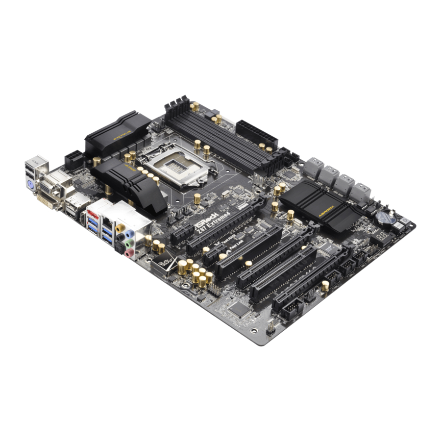
Page 17: Motherboard Layout
Z87 Extreme4 1.4 Motherboard Layout CPU_FAN2 CPU_FAN1 ATX12V1 HDMI_IN1 USB 3.0 T: USB0 B: USB1 USB 3.0 Top: T: USB2 RJ-45 B: USB3 CHA_FAN3 CHA_FAN2 PWR_FAN1 USB3_8 Z87 Extreme4 PCIE1 PCI Express 3.0 PCIE2 Purity Sound Fast RAM PCIE3 Fast LAN... - Page 18 No. Description ATX 12V Power Connector (ATX12V1) Chassis Fan Connector (CHA_FAN2) CPU Fan Connector (CPU_FAN1) CPU Fan Connector (CPU_FAN2) 2 x 240-pin DDR3 DIMM Slots (DDR3_A1, DDR3_B1) 2 x 240-pin DDR3 DIMM Slots (DDR3_A2, DDR3_B2) ATX Power Connector (ATXPWR1) USB 3.0 Header (USB3_4_5) (ASMedia Hub) USB 3.0 Header (USB3_6_7) (ASMedia Hub) Vertical Type A USB 3.0 (USB3_12) SATA3 Connectors (SATA3_A0_A1)
-
Page 19: I/O Panel
Z87 Extreme4 1.5 I/O Panel No. Description No. Description USB 2.0 Ports (USB01) Microphone (Pink) VGA Port Optical SPDIF Out Port Display Port USB 3.0 Ports (USB3_23) eSATA Connector*** USB 3.0 Ports (USB3_01) LAN RJ-45 Port* HDMI-In Port Central / Bass (Orange) - Page 20 * There are two LEDs on each LAN port. Please refer to the table below for the LAN port LED indications. ACT/LINK LED SPEED LED LAN Port Activity / Link LED Speed LED Status Description Status Description No Link 10Mbps connection Blinking Data Activity Orange...
-
Page 21: Chapter 2 Installation
Chapter 2 Installation This is an ATX form factor motherboard. Before you install the motherboard, study the configuration of your chassis to ensure that the motherboard fits into it. Pre-installation Precautions Take note of the following precautions before you install motherboard components or change any motherboard settings. -
Page 22: Installing The Cpu
2.1 Installing the CPU 1. Before you insert the 1150-Pin CPU into the socket, please check if the PnP cap is on the socket, if the CPU surface is unclean, or if there are any bent pins in the socket. Do not force to insert the CPU into the socket if above situation is found. - Page 23 Z87 Extreme4...
- Page 24 Please save and replace the cover if the processor is removed. The cover must be placed if you wish to return the motherboard for after service.
-
Page 25: Installing The Cpu Fan And Heatsink
Z87 Extreme4 2.2 Installing the CPU Fan and Heatsink... -
Page 26: Installing Memory Modules (Dimm)
2.3 Installing Memory Modules (DIMM) This motherboard provides four 240-pin DDR3 (Double Data Rate 3) DIMM slots, and supports Dual Channel Memory Technology. 1. For dual channel configuration, you always need to install identical (the same brand, speed, size and chip-type) DDR3 DIMM pairs. 2. - Page 27 Z87 Extreme4...
-
Page 28: Expansion Slots (Pci And Pci Express Slots)
2.4 Expansion Slots (PCI and PCI Express Slots) There are 2 PCI slots and 5 PCI Express slots on the motherboard. Before installing an expansion card, please make sure that the power supply is switched off or the power cord is unplugged. Please read the documentation of the expansion card and make necessary hardware settings for the card before you start the installation. -
Page 29: Jumpers Setup
Z87 Extreme4 2.5 Jumpers Setup The illustration shows how jumpers are setup. When the jumper cap is placed on the pins, the jumper is “Short”. If no jumper cap is placed on the pins, the jumper is “Open”. The illustration shows a 3-pin jumper whose pin1 and pin2 are “Short”... - Page 30 BIOS Selection Jumper (BIOS_SEL1) Default Backup BIOS (see p.11, No. 16) (Main BIOS) This motherboard has two BIOS onboard, a main BIOS (BIOS_A) and a backup BIOS (BIOS_B), which enhances protection for the safety and stability of your system. Normally, the system works on the main BIOS. However, if the main BIOS is corrupted or damaged, please use a jumper cap to short pin2 and pin3, then the backup BIOS will take over on the next system boot.
-
Page 31: Onboard Headers And Connectors
Z87 Extreme4 2.6 Onboard Headers and Connectors Onboard headers and connectors are NOT jumpers. Do NOT place jumper caps over these headers and connectors. Placing jumper caps over the headers and connectors will cause permanent damage to the motherboard. System Panel Header... - Page 32 Power LED Header Please connect the chassis (3-pin PLED1) power LED to this header PLED- PLED+ PLED+ (see p.11, No. 21) to indicate the system’s power status. Serial ATA3 Connectors These eight SATA3 (SATA3_0_1: connectors support SATA see p.11, No. 12) data cables for internal (SATA3_2_3: storage devices with up...
- Page 33 Z87 Extreme4 Front Panel Audio Header This header is for GN D OUT2_L (9-pin HD_AUDIO1) connecting audio devices J_SENSE PRESENCE# OUT2_R (see p.11, No. 29) to the front audio panel. MIC_RET MIC2_R OUT_RET MIC2_L 1. High Definition Audio supports Jack Sensing, but the panel wire on the chassis must sup- port HDA to function correctly.
- Page 34 CPU Fan Connectors This motherboard pro- FAN_SPEED_CONTROL FAN_SPEED (4-pin CPU_FAN1) vides a 4-Pin CPU fan + 12V (see p.11, No. 3) (Quiet Fan) connector. GN D If you plan to connect a (3-pin CPU_FAN2) 3-Pin CPU fan, please FAN_SPEED + 12V (see p.11, No.
-
Page 35: Smart Switches
Z87 Extreme4 2.7 Smart Switches The motherboard has three smart switches: Power Switch, Reset Switch and Clear CMOS Switch, allowing users to quickly turn on/off the system, reset the system or clear the CMOS values. Power Switch Power Switch allows users... -
Page 36: Dr. Debug
2.8 Dr. Debug Dr. Debug is used to provide code information, which makes troubleshooting even easier. Please see the diagrams below for reading the Dr. Debug codes. Code Description Please check if the CPU is installed correctly and then clear CMOS. - Page 37 Z87 Extreme4 Problem related to USB devices. Please try removing all USB devices. Problem related to memory. Please re-install the CPU and memory then clear CMOS. If the problem still exists, please install only one memory module or try using other memory modules.
-
Page 38: Using The Hdmi-In Port
2.9 Using the HDMI-In Port The HDMI-In port on this motherboard lets you easily switch between PC screen (on-board VGA) and external video source on the same monitor. This function saves you the hassle of switching cables back and forth when you want to display the screen of another device, such as smartphone, tablet, camcorder, DVD player, or another PC, onto the PC monitor. - Page 39 Z87 Extreme4 Connection Diagram HDMI Adapter Power Source...
- Page 40 Step 1 Connect your monitor to the HDMI-Out port on the motherboard via an HDMI cable. Step 2 Connect an external devices with HDMI output to the HDMI-In port on the motherboard via an HDMI cable. Step 3 Double-click the “A-Tuning“ icon on the desktop and find "HDMI-IN"...
-
Page 41: Sli Tm And Quad Sli
Z87 Extreme4 2.10 SLI and Quad SLI Operation Guide ® This motherboard supports NVIDIA and Quad SLI (Scalable Link Interface) technology that allows you to install up to two identical PCI Express x16 ® graphics cards. Currently, NVIDIA and Quad SLI technology supports ®... - Page 42 Step 3 Align and insert the ASRock SLI_ Bridge_2S Card to the goldfingers on each graphics card. Make sure the ASRock SLI_ Bridge_2S Card is firmly in place. SLI_Bridge_2S Card ASRock SLI_Bridge_2S Card Step 4 Connect a VGA cable or a DVI cable to the...
-
Page 43: Driver Installation And Setup
Z87 Extreme4 2.10.2 Driver Installation and Setup Install the graphics card drivers to your system. After that, you can enable the ® Multi-Graphics Processing Unit (GPU) in the NVIDIA nView system tray utility. Please follow the below procedures to enable the multi-GPU. -
Page 44: Tm And Quad Crossfirex
2.11 CrossFireX , 3-Way CrossFireX and Quad CrossFireX Operation Guide This motherboard supports CrossFireX , 3-way CrossFireX and Quad CrossFireX that allows you to install up to three identical PCI Express x16 graphics cards. Currently CrossFireX , 3-way CrossFireX and Quad ®... -
Page 45: Installing Three Crossfirex
Z87 Extreme4 Step 3 Connect a VGA cable or a DVI cable to the monitor connector or the DVI connec- tor of the graphics card that is inserted to PCIE2 slot. 2.11.2 Installing Three CrossFireX -Ready Graphics Cards Step 1... -
Page 46: Driver Installation And Setup
2.11.3 Driver Installation and Setup Step 1 Power on your computer and boot into OS. Step 2 Remove the AMD drivers if you have any VGA drivers installed in your system. The Catalyst Uninstaller is an optional download. We recommend using this utility to un- install any previously installed Catalyst drivers prior to installation. -
Page 47: Chapter 3 Software And Utilities Operation
Z87 Extreme4 Chapter 3 Software and Utilities Operation 3.1 Installing Drivers The Support CD that comes with the motherboard contains necessary drivers and useful utilities that enhance the motherboard’s features. Running The Support CD To begin using the support CD, insert the CD into your CD-ROM drive. The CD automatically displays the Main Menu if “AUTORUN”... -
Page 48: A-Tuning
3.2 A-Tuning A-Tuning is ASRock’s multi purpose software suite with a new interface, more new features and improved utilities, including XFast RAM, Dehumidifier, Good Night LED, FAN-Tastic Tuning, OC Tweaker and a whole lot more. 3.2.1 Installing A-Tuning When you install the all-in-one driver to your system from ASRock’s support CD, A-Tuning will be auto-installed as well. - Page 49 Z87 Extreme4 Tools Various tools and utilities. XFast RAM Boost the system’s performance and extend the HDD’s or SDD’s lifespan! Create a hidden partition, then assign which files should be stored in the RAM drive. Fast Boot Fast Boot minimizes your computer's boot time. Please note that Ultra Fast mode is only supported by Windows 8 and the VBIOS must support UEFI GOP if you are using an external graphics card.
-
Page 50: System Info
Dehumidifier Prevent motherboard damages due to dampness. Enable this function and configure the period of time until the computer powers on, and the duration of the dehumidifying process. HDMI-IN Connect two different devices to one monitor and toggle between the primary and secondary screen without replugging the connectors every time. - Page 51 Z87 Extreme4 Tech Service Contact Tech Service.
-
Page 52: Intel® Rapid Start Technology
3.3 Intel® Rapid Start Technology Intel® Rapid Start Technology enables your system to wake up faster from deep sleep, saving time and power consumption. Feel secure to know that your system will resume to working condition even if an unexpected power loss happens while the PC is in sleep mode. -
Page 53: Setup Guide
3.3.2 Setup Guide Configuring Rapid Start Step 1 Run ASRock Rapid Start utility from Start -> All Programs -> ASRock Utility. Step 2 If you have more than one hard drives in your system, you must select one, then choose the Partition Size desired for your hidden partition and click on Create. The system will automatically create a hidden partition according to your settings. - Page 54 Step 3 When prompted to restart after the setup, click Yes to reboot. Step 4 Double-click the Intel® Rapid Start Technology Manager icon in the Windows system tray.
- Page 55 Z87 Extreme4 Step 5 Make sure Rapid Start is on. Drag the slider to configure the time. For example, if the timer value is set to ten minutes, the system will enable Rapid Start mode after entering sleep state for ten minutes. If the timer is set to 0 minutes, Windows will immediately enable Rapid Start mode as it enters sleep state.
- Page 56 state for a period of time. The power of the computer in Rapid Start mode can be cut off, it will not cause data loss of the programs or files you were executing before entering sleep state. When you wish to continue to use the computer just hit the power button, the system will rapidly return to Windows, the programs and files which you were using before entering sleep state will be accessible immediately.
-
Page 57: Intel® Smart Connect Technology
Z87 Extreme4 3.4 Intel® Smart Connect Technology Intel® Smart Connect Technology is a feature that periodically wakes your computer from Windows® sleep state to refresh email or social networking applications. It saves your waiting time and keeps the content always up-to-date. - Page 58 3.4.2 Setup Guide Installing ASRock Smart Connect Utility Step 1 Install ASRock Smart Connect Utility, which is located in the folder at the following path of the Support CD: \ ASRock Utility > Smart Connect. Step 2 Once installed, run ASRock Smart Connect from your desktop or go to Windows...
- Page 59 Z87 Extreme4 Step 3 Click the Add button. Take Foxmail as an example, add Foxmail to the Application list. Step 4 Select Foxmail from the Application List, then click the arrow pointing right to add this application to the Smart Connect List.
- Page 60 Step 6 Double-click the Intel® Smart Connect Technology Manager icon in the Windows system tray. Step 7 Drag the slider to configure how often the system will connect to the network to download updates. Shorter durations will provide more frequent updates, but may cause more power consumption.
- Page 61 Z87 Extreme4 The system will wake up from sleep state periodically, and then start to update Foxmail. The screen will not display anything so the computer can maintain minimum power usage. Afterwards, the system will automatically return to sleep state again.
-
Page 62: Intel® Remote Wake Technology
3.5 Intel® Remote Wake Technology Intel® Remote Wake Technology allows you to use programs or services over the Internet to wake up your home computer from energy efficient sleep mode. Before configuring this feature, verify the following. • Remote Wake has been enabled in "Intel® Smart Connect Technology Manager". - Page 63 Z87 Extreme4 Step 3 A new mesh window will pop up. Enter a mesh name and password. Step 4 Select all the checkboxes and click Create Mesh. Downloading and Installing Mesh Agent Step 1 Click Install on the My Account page.
- Page 64 Step 4 Click Install / Update. Step 5 Wait a minute for the New Machine to appear in "My Device".
- Page 65 Z87 Extreme4 Step 6 Check whether "Intel Remote Wake" appeared or not. Step 7 Click on Power Actions. Step 8 Click on Wake or Sleep.
- Page 66 Waking up a PC using mobile device. Before waking up your home computer using a mobile device, please log out of MeshCentral on other previously used computers or devices. Step 1 Login to meshcentral.com/m. Step 2 Select a Machine. Step 3 Click on Wake or Sleep.
-
Page 67: Configuring And Using Splashtop
Download and install Streamer on your home computer, which is located in the fold- er at the following path of the Support CD: \ ASRock Utility > Splashtop Streamer. Then enter your Splashtop Account. If you have not created a Splashtop acount, create one. -
Page 68: Using Remote Control
Using Remote Control Step 1 In "Splashtop 2”, tap an online machine from the list to connect to your home computer. Step 2 Start remotely accessing your home computer. The functionality and price of the Splashtop APP and subscription fee is subject to change. - Page 69 Z87 Extreme4 Accessing Data Playing Video...
-
Page 70: Intel® Extreme Tuning Utility (Ixtu)
3.6 Intel® Extreme Tuning Utility (IXTU) Intel® Extreme Tuning Utility is an overclocking utility that allows you to tune and tweak your system for performance optimization while still maintaining system stability. Double-click on your desktop to access Intel® Extreme Tuning Utility. Overclocking may affect your system’s stability, or even cause damage to the components and devices of your system. -
Page 71: System Information
Z87 Extreme4 System Information Displays the major information of your system. Manual Tuning Manual Tuning shows the major readings of your system and allows you to tune the parameters, including voltage for the CPU core, GPU, and TurboBoost functions. Click Apply to apply the settings. Click Save to save your current settings as a profile. -
Page 72: Start8
3.7.1 Installing Start8 Install Start8, which is located in the folder at the following path of the Support CD: \ ASRock Utility > Start8. 3.7.2 Configuring Start8 Style Select between the Windows 7 style and Windows 8 style Start Menu. Then select... - Page 73 Z87 Extreme4 Configure Configure provides configuration options, including icon sizes, which shortcuts you want Start Menu to display, quick access to recently used apps, the functionality of the power button, and more. Control...
- Page 74 Control lets you configure what a click on the start button or a press on the Windows key does. Desktop Desktop allows you to disable the hot corners when you are working on the desktop. It also lets you choose whether or not the system boots directly into desktop mode and bypass the Metro user interface.
-
Page 75: Chapter 4 Uefi Setup Utility
Chapter 4 UEFI SETUP UTILITY 4.1 Introduction ASRock Interactive UEFI is a blend of system configuration tools, cool sound effects and stunning visuals. Not only will it make BIOS setup less difficult but also a lot more amusing. This section explains how to use the UEFI SETUP UTILITY to configure your system. -
Page 76: Navigation Keys
4.1.2 Navigation Keys Use < > key or < > key to choose among the selections on the menu bar, and use < > key or < > key to move the cursor up or down to select items, then press <Enter>... -
Page 77: Main Screen
When you enter the UEFI SETUP UTILITY, the Main screen will appear and display the system overview. Active Page on Entry Select the default page when entering the UEFI setup utility. UEFI Guide UEFI Guide is a quick tutorial for ASRock's UEFI setup Utility. You may abort the tutorial by pressing "esc". -
Page 78: Oc Tweaker Screen
4.3 OC Tweaker Screen In the OC Tweaker screen, you can set up overclocking features. Because the UEFI software is constantly being updated, the following UEFI setup screens and descriptions are for reference purpose only, and they may not exactly match what you see on your screen. -
Page 79: Spread Spectrum
Z87 Extreme4 CPU Configuration CPU Ratio The CPU speed is determined by the CPU Ratio multiplied with the BCLK. Increasing the CPU Ratio will increase the internal CPU clock speed without affecting the clock speed of other components. CPU Cache Ratio The CPU Internal Bus Speed Ratio. -
Page 80: Dram Timing Configuration
Short Duration Power Limit Configure Package Power Limit 2 in watts. When the limit is exceeded, the CPU ratio will be lowered immediately. A lower limit can protect the CPU and save power, while a higher limit may improve performance. Primary Plane Current Limit Configure the current limit of the CPU under Turbo Mode in ampere. -
Page 81: Dram Configuration
Z87 Extreme4 DRAM Configuration DRAM Tweaker Fine tune the DRAM settings by leaving marks in checkboxes. Click OK to confirm and apply your new settings. CAS# Latency (tCL) The time between sending a column address to the memory and the beginning of the data in response. - Page 82 Command Rate (CR) The delay between when a memory chip is selected and when the first active command can be issued. Write Recovery Time (tWR) The amount of delay that must elapse after the completion of a valid write operation, before an active bank can be precharged.
- Page 83 Z87 Extreme4 tRDRDDR Configure between module read to read delay from different ranks. tRDRDDD Use this to change DRAM tRWSR Auto/Manual settings. The default is [Auto]. tWRRD Configure between module write to read delay. tWRRDDR Configure between module write to read delay from different ranks.
- Page 84 IO-L (CHA) Configure IO latency for channel A. IO-L (CHB) Configure IO latency for channel B. ODT WR (CHA) Configure the memory on die termination resistors' WR for channel A. ODT WR (CHB) Configure the memory on die termination resistors' WR for channel B. ODT NOM (CHA) Use this to change ODT (CHA) Auto/Manual settings.
- Page 85 Z87 Extreme4 CPU Override Voltage Configure the voltage added to the CPU when the system is under heavy load. CPU Voltage Offset Configure the dynamic CPU voltage added to the CPU. CPU Cache Override Voltage Add voltage to the CPU Cache when the system is under heavy load.
- Page 86 VCORE External Offset The fixed external voltage input to the CPU. DRAM Voltage Use this to configure DRAM Voltage. The default value is [Auto]. PCH 1.05V Voltage Chipset 1.05V Voltage. Use default settings for best performance. PCH 1.5V Voltage I/O 1.5V Voltage. Use default settings for best performance.
-
Page 87: Advanced Screen
Z87 Extreme4 4.4 Advanced Screen In this section, you may set the configurations for the following items: CPU Configuration, Chipset Configuration, Storage Configuration, Intel® Rapid Start Technology, Intel® Smart Connect Technology, Super IO Configuration, ACPI Con- figuration and USB Configuration. -
Page 88: Cpu Configuration
4.4.1 CPU Configuration Active Processor Cores Select the number of cores to enable in each processor package. CPU C States Support Enable CPU C States Support for power saving. It is recommended to keep C3, C6 and C7 all enabled for better power saving. Enhanced Halt State (C1E) Enable Enhanced Halt State (C1E) for lower power consumption. -
Page 89: Intel Virtualization Technology
Z87 Extreme4 CPU Thermal Throttling Enable CPU internal thermal control mechanisms to keep the CPU from overheat- ing. No-Execute Memory Protection Processors with No-Execution Memory Protection Technology may prevent certain classes of malicious buffer overflow attacks. Intel Virtualization Technology Intel Virtualization Technology allows a platform to run multiple operating systems and applications in independent partitions, so that one computer system can function as multiple virtual systems. -
Page 90: Chipset Configuration
4.4.2 Chipset Configuration Primary Graphics Adapter Select a primary VGA. VT-d Intel® Virtualization Technology for Directed I/O helps your virtual machine monitor better utilize hardware by improving application compatibility and reliability, and providing additional levels of manageability, security, isolation, and I/O performance. -
Page 91: Render Standby
Z87 Extreme4 IGPU Multi-Monitor Select disable to disable the integrated graphics when an external graphics card is installed. Select enable to keep the integrated graphics enabled at all times. Render Standby Power down the render unit when the GPU is idle for lower power consumption. -
Page 92: Storage Configuration
4.4.3 Storage Configuration SATA Controller(s) Enable/disable the SATA controllers. SATA Mode Selection IDE: For better compatibility. AHCI: Supports new features that improve performance. RAID: Combine multiple disk drives into a logical unit. AHCI (Advanced Host Controller Interface) supports NCQ and other new features that will improve SATA disk performance but IDE mode does not have these advantages. - Page 93 Z87 Extreme4 ASMedia SATA3 Mode IDE: For better compatibility. AHCI: Supports new features that improve performance. SATA Boot ROM Enable to load ASMedia option ROM for better compatibility. Disable for faster boot time.
-
Page 94: Intel® Rapid Start Technology
4.4.4 Intel® Rapid Start Technology ® Intel Rapid Start Technology Intel® Rapid Start Technology is a new zero power hibernation mode which allows users to resume in just 5-6 seconds. -
Page 95: Intel® Smart Connect Technology
Z87 Extreme4 4.4.5 Intel® Smart Connect Technology ® Intel Smart Connect Technology ® Intel Smart Connect Technology automatically updates your email and social networks, such as Twitter, Facebook, etc. while the computer is in sleep mode. -
Page 96: Super Io Configuration
4.4.6 Super IO Configuration Serial Port Enable or disable the Serial port. Serial Port Address Select the address of the Serial port. Infrared Port Enable or disable the Infrared port. -
Page 97: Acpi Configuration
Z87 Extreme4 4.4.7 ACPI Configuration Suspend to RAM Select disable for ACPI suspend type S1. It is recommended to select auto for ACPI S3 power saving. Check Ready Bit Enable to enter the operating system after S3 only when the hard disk is ready, this is recommended for better system stability. - Page 98 Ring-In Power On Allow the system to be waked up by onboard COM port modem Ring-In signals. RTC Alarm Power On Allow the system to be waked up by the real time clock alarm. Set it to By OS to let it be handled by your operating system.
-
Page 99: Usb Configuration
Z87 Extreme4 4.4.8 USB Configuration USB Controller Enable or disable all the USB ports. USB 3.0 Controller Enable or disable all the USB 3.0 ports. Legacy USB Support Enable or disable Legacy OS Support for USB 2.0 devices. If you encounter USB compatibility issues it is recommended to disable legacy USB support. -
Page 100: Tools
In order to prevent users from bypassing OMG, guest accounts without permission to modify the system time are required. UEFI Tech Service Contact ASRock Tech Service if you are having trouble with your PC. Please setup network configuration before using UEFI Tech Service. Easy RAID Installer Easy RAID Installer helps you to copy the RAID driver from the support CD to your USB storage device. -
Page 101: Instant Flash
ROM and execute Secure Backup UEFI to duplicate the current working ROM image to the secondary flash ROM. Internet Flash ASRock Internet Flash downloads and updates the latest UEFI firmware version from our servers for you. Please setup network configuration before using Internet Flash. - Page 102 Dehumidifier Function If Dehumidifier Function is enabled, the computer will power on automatically to dehumidify the system after entering S4/S5 state. Dehumidifier Period Configure the period of time until the computer powers on and enables Dehumidifier after entering S4/S5 state. Dehumidifier Duration Configure the duration of the dehumidifying process before it returns to S4/S5 state.
-
Page 103: Hardware Health Event Monitoring Screen
Z87 Extreme4 4.6 Hardware Health Event Monitoring Screen This section allows you to monitor the status of the hardware on your system, including the parameters of the CPU temperature, motherboard temperature, fan speed and voltage. CPU Fan 1 & 2 Setting Select a fan mode for CPU Fans 1&2, or choose Customize to set 5 CPU... -
Page 104: Boot Screen
4.7 Boot Screen This section displays the available devices on your system for you to configure the boot settings and the boot priority. Fast Boot Fast Boot minimizes your computer's boot time. In fast mode you may not boot from an USB storage device. Ultra Fast mode is only supported by Windows 8 and the VBIOS must support UEFI GOP if you are using an external graphics card. - Page 105 Z87 Extreme4 Full Screen Logo Enable to display the boot logo or disable to show normal POST messages. AddOn ROM Display Enable AddOn ROM Display to see the AddOn ROM messages or configure the AddOn ROM if you've enabled Full Screen Logo. Disable for faster boot speed.
- Page 106 Launch PXE OpROM Policy Select UEFI only to run those that support UEFI option ROM only. Select Legacy only to run those that support legacy option ROM only. Do not launch? Launch Storage OpROM Policy Select UEFI only to run those that support UEFI option ROM only. Select Legacy only to run those that support legacy option ROM only.
-
Page 107: Security Screen
Z87 Extreme4 4.8 Security Screen In this section you may set or change the supervisor/user password for the system. You may also clear the user password. Supervisor Password Set or change the password for the administrator account. Only the administrator has authority to change the settings in the UEFI Setup Utility. -
Page 108: Exit Screen
4.9 Exit Screen Save Changes and Exit When you select this option the following message, “Save configuration changes and exit setup?” will pop out. Select [OK] to save changes and exit the UEFI SETUP UTILITY. Discard Changes and Exit When you select this option the following message, “Discard changes and exit setup?”... -
Page 109: Contact Information
Z87 Extreme4 Contact Information If you need to contact ASRock or want to know more about ASRock, you’re welcome to visit ASRock’s website at http://www.asrock.com; or you may contact your dealer for further information. For technical questions, please submit a support request form at http://www.asrock.com/support/tsd.asp...