TP-Link TL-ER604W User Manual
Wireless n gigabit broadband vpn router
Hide thumbs
Also See for TL-ER604W:
- User manual (217 pages) ,
- Datasheet (4 pages) ,
- Quick install manual (2 pages)

Related Manuals for TP-Link TL-ER604W


Summary of Contents for TP-Link TL-ER604W
- Page 1 TL-ER604W Wireless N Gigabit Broadband VPN Router Rev1.0.1 1910010844...
-
Page 2: Fcc Statement
No part of the specifications may be reproduced in any form or by any means or used to make any derivative such as translation, transformation, or adaptation without permission from TP-LINK TECHNOLOGIES CO., LTD. Copyright © 2013 TP-LINK TECHNOLOGIES CO., LTD. All rights reserved. http://www.tp-link.com FCC STATEMENT This equipment has been tested and found to comply with the limits for a Class A digital device, pursuant to part 15 of the FCC Rules. -
Page 3: Table Of Contents
CONTENTS ........................1 Package Contents ....................2 Chapter 1 About this Guide Intended Readers ........................2 Conventions ...........................2 Overview of this Guide ......................2 ......................3 Chapter 2 Introduction Overview of the Router ......................3 Features..........................4 Appearance..........................6 2.3.1 Front Panel ........................6 2.3.2 Rear Panel.........................7 ......................8 Chapter 3 Configuration Network..........................8 3.1.1 Status.........................8... - Page 4 Advanced ..........................55 3.4.1 NAT..........................55 3.4.2 Traffic Control ......................63 3.4.3 Session Limit ......................66 3.4.4 Load Balance......................68 3.4.5 Routing ........................72 Firewall..........................77 3.5.1 Anti ARP Spoofing ....................77 3.5.2 Attack Defense ......................80 3.5.3 MAC Filtering ......................82 3.5.4 Access Control......................82 3.5.5 App Control......................88 VPN............................89 3.6.1 IKE...........................90 3.6.2 IPsec........................94...
- Page 5 3.8.7 Logs ........................128 ......................130 Chapter 4 Application Network Requirements.......................130 Network Topology.......................131 Configurations........................131 4.3.1 Internet Setting ......................131 4.3.2 VPN Setting ......................133 4.3.3 Network Management....................139 4.3.4 Network Security....................143 ................148 Appendix A Hardware Specifications ......................149 Appendix B ....................151 Appendix C Glossary -IV-...
-
Page 6: Package Contents
Package Contents The following items should be found in your package: One TL-ER604W Router One Power Adapter One RJ45 Ethernet Cable Quick Installation Guide Resource CD Note: Make sure that the package contains the above items. If any of the listed items is damaged or missing,... -
Page 7: Chapter 1 About This Guide
Chapter 1 About this Guide This User Guide contains information for setup and management of TL-ER604W Router. Please read this guide carefully before operation. 1.1 Intended Readers This Guide is intended for Network Engineer and Network Administrator. 1.2 Conventions In this Guide the following conventions are used: The Router or TL-ER604W mentioned in this Guide stands for TL-ER604W SafeStream Wireless ... -
Page 8: Chapter 2 Introduction
Furthermore, together with many useful features including hardware-based WiFi On/Off button, Guest Networking, App Control, and PPPoE Server functions, TL-ER604W is an ideal network solution for home or small office consumers. -
Page 9: Features
+ Possessing MAC Filtering function to block the access of illegal hosts. Flexible Traffic Control + Featured Bandwidth Control with flexible bandwidth management to automatically control the bandwidth of the host in bi-direction to avoid bandwidth over occupation, as well as optimize bandwidth usage. - Page 10 Supports Virtual Server, Port Triggering, ALG, Static Route and RIP v1/v2 Built-in Switch supporting Port Mirror, Port VLAN, Rate Control and so on Supports to change the MAC address of LAN and WAN port Supports Logs, Statistics, Time setting ...
-
Page 11: Appearance
2.3 Appearance 2.3.1 Front Panel The front panel of TL-ER604W is shown as the following figure. Figure 2-1 Front Panel LEDs Status Indication The Router is powered on The Router is powered off or power supply is abnormal Flashing... -
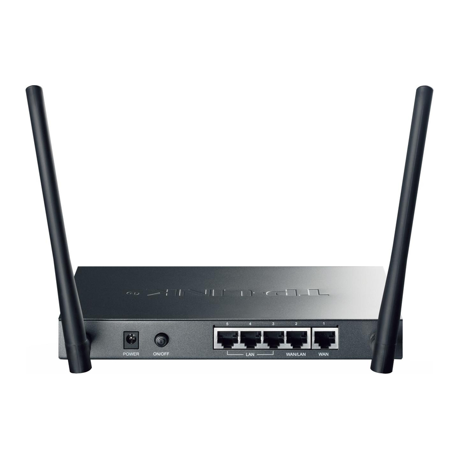
Page 12: Rear Panel
Wifi button Press this button to enable or disable WI-FI. 2.3.2 Rear Panel The rear panel of TL-ER604W is shown as the following figure. Figure 2-2 Rear Panel Antenna The router provides two external detachable antennas for receiving and transmitting the wireless data. -
Page 13: Chapter 3 Configuration
Figure 3-1 Status 3.1.2 System Mode The TL-ER604W Router can work in three modes: NAT, Non-NAT and Classic. If your Router is hosting your local network’s connection to the Internet with a network topology as the Figure 3-2 shown, you can set it to NAT mode. - Page 14 Figure 3-2 Network Topology - NAT Mode If your Router is connecting the two networks of different areas in a large network environment with a network topology as the Figure 3-3 shown, and forwards the packets between these two networks by the Routing rules, you can set it to Non-NAT mode.
-
Page 15: Wan
3.1.3 WAN 3.1.3.1 WAN Mode TL-ER604W provides two adjustable WAN ports. You can set the number of WAN ports on this page. Choose the menu Network→WAN→WAN Mode to load the following page. -10-... - Page 16 Note: By default, TL-ER604W is set to work in the mode of dual WAN ports. 3.1.3.2 WAN1 TL-ER604W provides the following six Internet connection types: Static IP, Dynamic IP, PPPoE/Russian PPPoE, L2TP/Russian L2TP, PPTP/Russian PPTP and BigPond.
- Page 17 Figure 3-7 WAN – Static IP The following items are displayed on this screen: Static IP Connection Type: Select Static IP if your ISP has assigned a static IP address for your computer. IP Address: Enter the IP address assigned by your ISP. If you are not clear, please consult your ISP.
- Page 18 Downstream Bandwidth: Specify the bandwidth for receiving packets on the port. Dynamic IP If your ISP (Internet Service Provider) assigns the IP address automatically, please choose the Dynamic IP connection type to obtain the parameters for WAN port automatically. Figure 3-8 WAN – Dynamic IP The following items are displayed on this screen: ...
- Page 19 the default value if no other MTU value is provided by your ISP. The broadcast requirement may not be supported by a few ISPs. Get IP Address by Unicast: Select this option if you can not get the IP address from your ISP even if with a normal network connection.
- Page 20 Gateway Address: Displays the Gateway Address assigned by your ISP. Primary DNS: Displays the IP address of your ISP’s Primary DNS. Secondary DNS: Displays the IP address of your ISP’s Secondary DNS. PPPoE If your ISP (Internet Service Provider) has provided the account information for the PPPoE connection, please choose the PPPoE connection type (Used mainly for DSL Internet service).
- Page 21 The following items are displayed on this screen: PPPoE Settings Select PPPoE if your ISP provides xDSL Virtual Dial-up connection. Connection Type: Click <Connect> to dial-up to the Internet and obtain the IP address. Click <Disconnect> to disconnect the Internet connection and release the current IP address.
- Page 22 ISP Address: Optional. Enter the ISP address provided by your ISP. It's null by default. Service Name: Optional. Enter the Service Name provided by your ISP. It's null by default. Enter the IP address of your ISP’s Primary DNS. Primary DNS: Secondary DNS: Optional.
- Page 23 “Connected” indicates that the Router has successfully obtained the IP parameters from your ISP. “Disconnected” indicates that the connection has been manually terminated or the request of the Router has no response from your ISP. Please ensure that your settings are correct and your network is connected well.
- Page 24 Figure 3-10 WAN - L2TP The following items are displayed on this screen: L2TP Settings Select L2TP if your ISP provides a L2TP connection. Click <Connect> Connection Type: to dial-up to the Internet and obtain the IP address. Click <Disconnect>...
- Page 25 MTU: MTU (Maximum Transmission Unit) is the maximum data unit transmitted by the physical network. It can be set in the range of 576-1460. The default MTU is 1460. It is recommended to keep the default value if no other MTU value is provided by your ISP. Active Mode: You can select the proper Active Mode according to your need.
- Page 26 L2TP Status Status: Displays the status of PPPoE connection. “Disabled” indicates that the L2TP connection type is not applied. “Connecting” indicates that the Router is obtaining the IP parameters from your ISP. “Connected” indicates that the Router has successfully obtained ...
- Page 27 Figure 3-11 WAN - PPTP The following items are displayed on this screen: PPTP Settings Connection Type: Select PPTP if your ISP provides a PPTP connection. Click <Connect> to dial-up to the Internet and obtain the IP address. Click <Disconnect> to disconnect the Internet connection and release the current IP address.
- Page 28 MTU: MTU (Maximum Transmission Unit) is the maximum data unit transmitted by the physical network. It can be set in the range of 576-1460. The default MTU is 1460. It is recommended to keep the default value if no other MTU value is provided by your ISP. You can select the proper Active mode according to your need.
- Page 29 PPTP Status Status: Displays the status of PPTP connection. “Disabled” indicates that the PPTP connection type is not applied. “Connecting” indicates that the Router is obtaining the IP parameters from your ISP. “Connected” indicates that the Router has successfully obtained ...
- Page 30 Figure 3-12 WAN – Bigpond The following items are displayed on this screen: BigPond Settings Select BigPond if your ISP provides a BigPond connection. Click Connection Type: <Connect> to dial-up to the Internet and obtain the IP address. Click <Disconnect>...
- Page 31 Auth Mode: You can select the proper Active mode according to your need. Manual: Select this option to manually activate or terminate the Internet connection by the <Connect> or <Disconnect> button. It is optimum for the dial-up connection charged on time. Always-on: Select this option to keep the connection always on.
-
Page 32: Lan
Note: To ensure the BigPond connection re-established normally, please restart the connection at least 5 seconds after the connection is off. 3.1.4 LAN 3.1.4.1 On this page, you can configure the parameters for LAN port of this router. Choose the menu Network→LAN→LAN to load the following page. Figure 3-13 LAN The following items are displayed on this screen: ... - Page 33 Figure 3-14 DHCP Settings The following items are displayed on this screen: DHCP Settings Enable or disable the DHCP server on your Router. To enable the DHCP Server: Router to assign the TCP/IP parameters to the computers in the LAN automatically, please select Enable.
-
Page 34: Dhcp Reservation
Secondary DNS: Optional. If a Secondary DNS Server address is available, enter it. .4.3 DHCP Client On this page, you can view the information about all the DHCP clients connected to the Router. Choose the menu Network→LAN→DHCP Client to load the following page. Figure 3-15 DHCP Client You can view the information of the DHCP clients in this table. -
Page 35: Mac Address
In a complex network topology with all the ARP bound devices, if you want to use TL-ER604W instead of the current router in a network node, you can just set the MAC address of TL-ER604W‘s LAN port the same to the MAC address of the previous router, which can avoid all the devices under this network node to update their ARP binding tables. -
Page 36: Switch
To avoid a conflict of MAC address on the local area network, it’s not allowed to set the MAC address of the Router’s LAN port to the MAC address of the current management PC. 3.1.6 Switch Some basic switch port management functions are provided by TL-ER604W, which facilitates you to monitor the traffic and manage the network effectively. 3.1.6.1... -
Page 37: Port Mirror
The following items are displayed on this screen: Statistics Unicast: Displays the number of normal unicast packets received or transmitted on the port. Displays the number of normal broadcast packets received or Broadcast: transmitted on the port. Pause: Displays the number of flow control frames received or transmitted on the port. - Page 38 Choose the menu Network→Switch→Port Mirror to load the following page. Figure 3-19 Port Mirror The following items are displayed on this screen: General Check the box to enable the Port Mirror function. If unchecked, it will Enable Port Mirror: be disabled.
-
Page 39: Rate Control
Application Example: To monitor all the traffic and analyze the network abnormity for an enterprise’s network, please set the Port Mirror function as below: Check the box before Enable Port Mirror to enable the Port Mirror function and select the Ingress &... -
Page 40: Port Config
Displays the port number. Port: Ingress Limit: Specify whether to enable the Ingress Limit feature. Ingress Rate: Specify the limit rate for the ingress packets. Egress Limit: Specify whether to enable Egress Limit feature. Specify the limit rate for the egress packets. Egress Rate: The first entry in Figure 3-20 indicates: The Ingress and Egress Limits are enabled for port 1. -
Page 41: Port Status
LAN. However, hosts in different VLANs cannot communicate with one another directly. Therefore, broadcast packets are limited in a VLAN. TL-ER604W provides the Port VLAN function, which allows you to create multiple logical VLANs for the LAN ports based on their port numbers. -
Page 42: Wireless
Select the desired VLAN for the port. VLAN: Tips: The Port VLAN can only be created among the LAN ports. 3.2 Wireless 3.2.1 Wireless Setting 3.2.1.1 Wireless Setting On this page you can configure the basic parameters of the wireless network. Choose the menu Wireless→Wireless Setting→Wireless Setting to load the following page. - Page 43 Region: Select your region from the drop-down list. This field specifies the region where the wireless function of the Router can be used. It may be illegal to use the wireless function of the Router in a region other than one of those specified in this field.
- Page 44 SSID: Enter a name for the wireless network. The same name of SSID(Service Set Identification) must be assigned to all wireless device in your network. Considering your wireless network security, the default SSID is set to be TP-LINK_XXXXXX (XXXXXX indicates the last unique six numbers of each Router’s MAC address).
- Page 45 Auth Type: Choose the Auth type of the WPA-PSK/WPA2-PSK security on the drop-down list. The default setting is Automatic, which can select WPA-PSK (Pre-shared key of WPA) or WPA2-PSK (Pre-shared key of WPA) automatically based on the wireless station's capability and request. Select the Encryption type including Automatic, TKIP, AES.
- Page 46 Encryption: Select the Encryption type. which including Automatic, TKIP, AES. The default setting is Automatic, which can select TKIP (Temporal Key Integrity Protocol) or AES Advanced Encryption Standard automatically based on the wireless station's capability and request. TKIP – TKIP is a security protocol used in the IEEE 802.11 wireless networking standard.
- Page 47 Key Format: Hexadecimal and ASCII formats are provided Hexadecimal format stands for any combination of hexadecimal digits (0-9, a-f, A-F) in the specified length. ASCII format stands for any combination of keyboard characters in the specified length. You can select the key based on need. Key Selected: WEP Key: Select which of the four keys will be used and enter the matching WEP key...
- Page 48 Figure 3- 25 Multi-SSID The following items are displayed on this screen: General Multi-SSID: Enable or disable the Multi-SSID. You can establish multiple wireless networks if Multi-SSID is enabled. Enable or disable the SSID Insulation. If enabled, the hosts accessing to SSID Insulation: the different SSID cannot be communicate with each other.
- Page 49 Security: Specify the security option of the wireless network. If you do not want to use wireless security, select “Disable Security”, otherwise select one Security option from the drop-down list. It’s strongly recommended to choose one of the security options to enable security. There are three wireless security options supported by the Router: WPA-PSK/WPA2-PSK, WPA/WPA2 and WEP.
- Page 50 Encryption: Select the Encryption type, which including Automatic, TKIP, AES. The default setting is Automatic, which can select TKIP (Temporal Key Integrity Protocol) or AES Advanced Encryption Standard automatically based on the wireless station's capability and request. TKIP – TKIP is a security protocol used in the IEEE 802.11 wireless networking standard.
- Page 51 Encryption: Select the Encryption type. which including Automatic, TKIP, AES. The default setting is Automatic, which can select TKIP (Temporal Key Integrity Protocol) or AES Advanced Encryption Standard automatically based on the wireless station's capability and request. TKIP – TKIP is a security protocol used in the IEEE 802.11 wireless networking standard.
- Page 52 Key Selected: You can select the key based on need. WEP Key: Select which of the four keys will be used and enter the matching WEP key that you create. Make sure these values are identical on all wireless stations in your network. Key Type: You can select the WEP key length (64-bit, or 128-bit, or 152-bit.) for encryption.
- Page 53 Choose the menu Wireless→Wireless Setting→WDS to load the following page. Figure 3-26 WDS Configuration General WDS: Enable or disable the WDS function. With this function, the Router can bridge two or more WLANs. Click this button; you can search the AP which runs in the current Scan: channel.
-
Page 54: Wireless Advanced
If the AP your Router is going to connect needs password, you need to fill the key in this blank. Tips: The Multi-SSID function will be disabled if WDS is enabled. 3.2.1.4 Wireless Advanced On this page, you can configure the wireless advanced parameters. Choose the menu Wireless→Wireless Setting→Wireless Advanced to load the following page. -
Page 55: Mac Filtering
Beacon Interval: Enter a value between 40-1000 milliseconds for Beacon Interval here. The beacons are the packets sent by the router to synchronize a wireless network. Beacon Interval value determines the time interval of the beacons. The default value is 100. Here you can specify the RTS (Request to Send) Threshold. -
Page 56: Host Status
Figure 3-28 MAC Filtering General Each SSID can be configured the MAC Address Filtering rules. You can select a SSID in the SSID drop-down list. To create a new SSID, please refer to 3.2.1.2 Multi-SSID. To control some of the hosts to access the wireless network, it is recommended to select “Enable Wireless MAC Address Filtering”... -
Page 57: User Group
Figure 3-29 Host Status General Select a SSID, the status of the host in this wireless network will display on the following table. Host Status MAC Address: Displays the MAC address of the host which access the Router by wireless connection. -
Page 58: User
Figure 3-30 Group Configuration The following items are displayed on this screen: Group Config Group Name: Specify a unique name for the group. Description: Give a description for the group. It's optional. List of Group In this table, you can view the information of the Groups and edit them by the Action buttons. 3.3.2 User On this page, you can configure the User for the group. -
Page 59: View
Description: Give a description to the user for identification. It's optional. List of User In this table, you can view the information of the Users and edit them by the Action buttons. 3.3.3 View On this page, you can configure the User View or Group View. Choose the menu User Group→View to load the following page. -
Page 60: Advanced
Group Structure: Click this button to view the tree structure of this group. All the members of this group will be displayed, including Users and sub-Groups. The Group Names are displayed in bold. Available Member: Displays the Users and the Groups which can be added into this group. Displays the members of this group, including Users and Groups. -
Page 61: One-To-One Nat
Enter the Original IP Address in the first checkbox and Translated Mapping IP Address: IP Address in the second checkbox. TL-ER604W allows mapping from LAN port to WAN port in LAN Mode. Interface: Select an interface for forwarding data packets. - Page 62 Status: Activate or inactivate the entry. List of Rules In this table, you can view the information of the entries and edit them by the Action buttons. The first entry in Figure 3-34 indicates: The IP address of host1 in local network is 192.168.0.128 and the WAN IP address after NAT mapping is specified to be 222.135.48.128.
- Page 63 Application Example: Network Requirements The LAN subnet of TL-ER604W is 192.168.0.0 /24, the subnet of VLAN2 under a three layer switch is 192.168.2.0 /24, while the subnet of VLAN3 is 192.168.3.0 /24. The IP of VLAN for cascading the switch to the Router is 192.168.0.2. Now the hosts within VLAN2 and VLAN3 desire to access the Internet.
-
Page 64: Virtual Server
The configured entries are as follows: Then set the corresponding Static Route entry, enter the IP address of the interface connecting the Router and the three layer switch into the Next Hop field. Choose the menu Advanced→Routing→Static Route to load the following page. The Static Route entry is as follows: 3.4.1.4 Virtual Server... - Page 65 Figure 3-36 Virtual Server The following items are displayed on this screen: Virtual Server Name: Enter a name for Virtual Server entries. Up to 28 characters can be entered. Select an interface for forwarding data packets. Interface: Enter the service port or port range the Router provided for accessing External Port: external network.
-
Page 66: Port Triggering
List of Rules In this table, you can view the information of the entries and edit them by the Action buttons. The first entry in Figure 3-36 indicates: This is a Virtual Server entry named host, all the TCP data packets from WAN1 to port 65534-65535 of the Router will be redirected to the port 65534-65535 of the LAN host with IP address of 192.168.0.103, and this entry is activated. - Page 67 Trigger Protocol: Select the protocol used for trigger port. Enter the incoming port number or range of port numbers. The Incoming Port: incoming port will open for follow-up connection after the trigger port initiates connection. Select the protocol used for incoming port. Incoming Protocol: Activate or inactivate the entry.
-
Page 68: Traffic Control
FTP ALG: Enable or disable FTP ALG. The default setting is enabled. It is recommended to keep the default setting if no special requirement. H.323 ALG: Enable or disable H.323 ALG. The default setting is enabled. H.323 is used for various applications such as NetMeeting and VoIP. - Page 69 The following items are displayed on this screen: General Disable Bandwidth Select this option to disable Bandwidth Control. Control: Select this option to enable Bandwidth Control all the time. Enable Bandwidth Control all the time: Enable Bandwidth With this option selected, the Bandwidth Control will take effect when the bandwidth usage reaches the specified value.
-
Page 70: Bandwidth Control
3.4.2.2 Bandwidth Control On this page, you can configure the Bandwidth Control function. Choose the menu Advanced→Traffic Control→Bandwidth Control to load the following page. Figure 3-40 Bandwidth Control The following items are displayed on this screen: Bandwidth Control Rule Direction: Select the data stream direction for the entry. -
Page 71: Session Limit
Specify the Limited Downstream Bandwidth for this entry. Limited Bandwidth (Down): Effective Time: Specify the time for the entry to take effect. Description: Give a description for the entry. Activate or inactivate the entry. Status: List of Rules You can view the information of the entries and edit them by the Action buttons. The first entry in Figure 3-40 indicates: The users within group “group1”... -
Page 72: Session List
Figure 3-41 Session Limit The following items are displayed on this screen: General Enable Session Check here to enable Session Limit, otherwise all the Session Limit entries will be disabled. Limit: Session Limit Select a group to define the controlled users. Group: Enter the max. -
Page 73: Load Balance
Figure 3-42 Session List In this table, you can view the session limit information of users configured with Session Limit. Click the <Refresh> button to get the latest information. 3.4.4 Load Balance In this part, you can configure the traffic sharing mode of the WAN ports to optimize the resource utilization. - Page 74 Figure 3-44 Policy Routing The following items are displayed on this screen: General Protocol: Select the protocol for the entry in the drop-down list. If the protocol you want to set is not in the list, you can add it to the list on 3.4.4.4 Protocol page.
-
Page 75: Link Backup
List of Rules You can view the information of the entries and edit them by the Action buttons. The first entry in Figure 3-44 indicates: All the packets with Source IP between 192.168.0.100 and 192.168.0.199 and Destination IP between 116.10.20.28 and 116.10.20.29 will be forwarded from WAN1 port, regardless of the port and protocol. - Page 76 WAN Config: The WAN port in the secondary WAN list will share the traffic for the WAN in the primary WAN list under the specified condition. Mode: You can select Timing or Failover Mode. Timing: Link Backup will be enabled if the specified effective time is reached. All the traffic on the primary WAN will switch to the backup WAN at the beginning of the effective time;...
-
Page 77: Routing
Figure 3-46 Protocol The following items are displayed on this screen: Protocol Enter a name to indicate a protocol. The name will display in the Name: drop-down list of Protocol on Access Rule page. Number: Enter the Number of the protocol in the range of 0-255. ... - Page 78 Figure 3-47 Static Route The following items are displayed on this screen: Static Route Destination: Enter the destination host the route leads to. Subnet Mask: Enter the Subnet Mask of the destination network. Next Hop: Enter the gateway IP address to which the packet should be sent next. Select the physical network interface, through which this route is Interface: accessible.
- Page 79 You can set a Static Route entry: Enter the WAN IP address of R1 (116.31.88.16) in the Next Hop field on the Static Route page of TL-ER604W as the following figure shown, then click the <Add> button to save the entry.
- Page 80 TL-ER604W supports both RIPv1 version and RIPv2 version, thus you can configure the RIP version based on the actual need to improve the network performance. Choose the menu Advanced→Routing→RIP to load the following page. Figure 3-48 RIP The following items are displayed on this screen: ...
- Page 81 data via this port. The IP address of next hop is 116.10.1.254 and the hop count is 1. The effective time of this entry is 1 second. Note: ● RIP function cannot be set if the Router is in NAT Mode. To set RIP function, please change the System Mode to Routing or Full Mode.
-
Page 82: Firewall
3.5 Firewall 3.5.1 Anti ARP Spoofing ARP (Address Resolution Protocol) is used for analyzing and mapping IP addresses to the corresponding MAC addresses so that packets can be delivered to their destinations correctly. ARP functions to translate the IP address into the corresponding MAC address and maintain an ARP Table in which the latest used IP address-to-MAC address mapping entries are stored. -
Page 83: Arp Scanning
It is recommended to check all the options. You should import the IP and MAC address of the host to IP-MAC Binding List and enable the corresponding entry before enabling “Permit the packets matching the IP-MAC Binding entries only”. When suffered ARP attack, the correct ARP information will be sent to the device suffering attack initiatively by GARP (Gratuitous ARP) packets, thus the error ARP information of the device will be replaced. -
Page 84: Arp List
Figure 3-51 ARP Scanning Enter the start and the end IP addresses into the Scanning IP Range field. Then click the <Scan> button, the Router will scan all the active hosts within the scanning range and display the result in the list. -
Page 85: Attack Defense
Figure 3-52 ARP List The configurations for the entries is the same as the configuration of List of Scanning Result on 3.5.1.2 ARP Scanning page. The unbound IP-MAC information will be replaced by new IP-MAC information or be automatically removed from the list if it has not been communicated with others for a long time. This period is regarded as the aging time of the ARP information. - Page 86 Figure 3-53 Attack Defense The following items are displayed on this screen: General Flood attack is a commonly used DoS (Denial of Service) attack, Flood Defense: including TCP SYN, UDP, ICMP and so on. It is recommended to select all the Flood Defense...
-
Page 87: Mac Filtering
MAC Filtering 3.5.3 On this page, you can control the Internet access of local hosts by specifying their MAC addresses. Choose the menu Firewall→MAC Filtering→MAC Filtering to load the following page. Figure 3-54 MAC Filtering The following items are displayed on this screen: General ... - Page 88 Figure 3-55 URL Filtering The following items are displayed on this screen: General To control the access to Internet for hosts in your private network, you are recommended to check the box before Enable URL Filtering and select a filtering rule based on the actual situation.
-
Page 89: Web Filtering
Application Example: Network Requirements: Prevent the local hosts from accessing Internet website www.aabbcc.com and downloading the files with suffix of “exe”. Configuration Procedure: Select Keywords mode and type ”exe“ in the field, select URL mode and type “www.aabbcc.com” as the following figure shows, and then click the <Add> button to make the setting take effect. 3.5.4.2 Web Filtering On this page, you can filter the desired web components. - Page 90 Figure 3-57 Access Rule The following items are displayed on this screen: Access Rules Policy: Select a policy for the entry: Block: When this option is selected, the packets obeyed the rule will not be permitted to pass through the Router. ...
- Page 91 means any IP). Group: Select a predefined group of users. You can set the group on3.3.1 Group. ANY: means for any users. Destination: Select the Destination IP Range for the entries, including the following two ways: IP/MASK: Enter an IP address or subnet mask. ("0.0.0.0/32" means any IP is acceptable).
- Page 92 services if needed. Choose the menu Firewall→Access Control→Service to load the following page. Figure 3-58 Service The following items are displayed on this screen: Service Name: Enter a name for the service. The name should not be more than 28 characters.
-
Page 93: App Control
App Control 3.5.5 .5.1 Control Rules On this page, you can enable the Application Rules function. Choose the menu Firewall→App Control→Control Rules to load the following page. Figure 3-59 Application Rules The following items are displayed on this screen: General Check the box before Enable Application Control to make the Application Control function take effect. -
Page 94: Vpn
The database refers to all the applications in the application list on the Application Rules page, you can download the latest database from http://www.tp-link.com, Click the <Browse> button and select the file, and then click the <Upgrade> button to upgrade the database. -
Page 95: Ike
As the packets are encapsulated and de-encapsulated in the Router, the tunneling topology implemented by encapsulating packets is transparent to users. The tunneling protocols supported by TL-ER604W contain Layer 3 IPsec and Layer 2 L2TP/PPTP. 3.6.1 IKE In the IPsec VPN, to ensure a secure communication, the two peers should encapsulate and de-encapsulate the packets using the information both known. - Page 96 Figure 3-62 IKE Policy The following items are displayed on this screen: IKE Policy Policy Name: Specify a unique name to the IKE policy for identification and management purposes. The IKE policy can be applied to IPsec policy. Exchange Mode: Select the IKE Exchange Mode in phase 1, and ensure the remote VPN peer uses the same mode.
-
Page 97: Ike Proposal
Local ID: The local WAN IP will be inputted automatically if IP Address type is selected. If Name type is selected, enter a name for the local device as the ID in IKE negotiation Select the remote ID type for IKE negotiation. IP Address: uses an IP Remote ID Type: address as the ID in IKE negotiation. - Page 98 Figure 3-63 IKE Proposal The following items are displayed on this screen: IKE Proposal Proposal Name: Specify a unique name to the IKE proposal for identification and management purposes. The IKE proposal can be applied to IPsec proposal. Select the authentication algorithm for IKE negotiation. Options include: Authentication: MD5: MD5 (Message Digest Algorithm) takes a message of arbitrary ...
-
Page 99: Ipsec
DH1: 768 bits DH2: 1024 bits DH3: 1536 bits List of IKE Proposal In this table, you can view the information of IKE Proposals and edit them by the action buttons. 3.6.2 IPsec IPsec (IP Security) is a set of services and protocols defined by IETF (Internet Engineering Task Force) to provide high security for IP packets and prevent attacks. - Page 100 Figure 3-64 IPsec Policy The following items are displayed on this screen: General You can enable/disable IPsec function for the Router here. IPsec Policy Policy Name: Specify a unique name to the IPsec policy. Up to 28 characters can be entered.
- Page 101 Remote Subnet: Specify IP address range on your remote network to identify which PCs on the remote network are covered by this policy. It's formed by IP address and subnet mask. WAN: Specify the local WAN port for this Policy. The "Remote Gateway"...
- Page 102 Status: Activate or inactivate the entry. Manual Mode IPsec Proposal: Select the IPsec Proposal. Only one proposal can be selected on Manual mode. You need to first create the IPsec Proposal. Incoming SPI: Specify the Incoming SPI (Security Parameter Index) manually. The Incoming SPI here must match the Outgoing SPI value at the other end of the tunnel, and vice versa.
-
Page 103: Ipsec Proposal
ESP Encryption Key-Out: Specify the outbound ESP Encryption Key manually if ESP protocol is used in the corresponding IPsec Proposal. The outbound key here must match the inbound ESP encryption key at the other end of the tunnel, and vice versa. ... - Page 104 Security Protocol: Select the security protocol to be used. Options include: (Authentication Header) provides data origin authentication, data integrity and anti-replay services. ESP: ESP (Encapsulating Security Payload) provides data encryption in addition to origin authentication, data integrity, and anti-replay services.
-
Page 105: L2Tp/Pptp
3.6.2.3 IPsec SA This page displays the information of the IPsec SA (Security Association). Choose the menu VPN→IPsec→IPsec SA to load the following page. Figure 3-66 IPsec SA Figure 3-66 displays the connection status of the NO.1 entry in the List of IPsec policy in Figure 3-64. As shown in the figure, the Router is using WAN2 for tunnel connection, and the IP address of WAN2 and the default gateway of remote peer are 172.30.70.151 and 172.30.70.161 respectively. - Page 106 3.6.3.1 L2TP/PPTP Tunnel On this page, you can configure the L2TP/PPTP VPN. Choose the menu VPN→L2TP/PPTP→L2TP/PPTP Tunnel to load the following page. Figure 3-67 L2TP/PPTP Tunnel The following items are displayed on this screen: General Specify whether to enable VPN-to-Internet function. If enabled, the Enable VPN-to-Internet: VPN client is permitted to access the LAN of the server and Internet.
- Page 107 Account Name: Enter the account name of L2TP/PPTP tunnel. It should be configured identically on server and client. Password: Enter the password of L2TP/PPTP tunnel. It should be configured identically on server and client. Select the network mode for the tunnel. Options include: Tunnel: LAN-to-LAN: Select this option when the L2TP/PPTP client is a ...
- Page 108 Status Activate or inactivate the entry. List of Configurations In this table, you can view your configurations of the tunnels and edit them by the action buttons. The No.1 entry in Figure 3-67 indicates: this tunnel is encapsulated by using L2TP. Its user name is test, the password can be configured, and the Router is configured in Client mode.
-
Page 109: Services
Figure 3-69 List of L2TP/PPTP Tunnel Figure 3-69 displays the connection status of the NO.1 entry in the list of tunnel in Figure 3-68. This tunnel has been successfully established. Each tunnel has a Tunnel ID and a Session ID. The ID value in client corresponds to that in server. - Page 110 Figure 3-70 General The following items are displayed on this screen: General PPPoE Server: Specify whether to enable the PPPoE Server function. Specify whether to enable the Dial-up Access Only function. If enabled, Dial-up Access Only: only the Dial-in Users and the user with Exceptional IP can access the Internet.
- Page 111 Authentication: Select the Authentication type. It can be Local authentication and Remote authentication. Select Local authentication for authentication in PPPoE server and select Remote authentication for authentication in the remote server. Select at least one authentication protocol for Local Authentication. Auth Protocol: PAP, transferring username and password in plain text in the ...
- Page 112 IP Address Range: Specify the start and the end IP address for IP Pool. The start IP address should not exceed the end address and the IP address ranges must not overlap. List of IP Pool In this table, you can view the information of IP Address Pools and edit them by the Action buttons. 3.7.1.3 Account On this page, you can configure the PPPoE account.
- Page 113 IP Address Pool: It's available on Dynamic mode. Select an IP Address Pool to make a range to assign dynamic IPs. Max Sessions: Specify the maximum number of sessions for the client. The default value is 1. Expiration Date: Specify the Expiration Date of the account. The default is 2099-1-1. Description: Enter the description for management and search purposes.
-
Page 114: E-Bulletin
Figure 3-73 Exceptional IP The following items are displayed on this screen: Exceptional IP IP Address Range: Specify the start and the end IP address to make an exceptional IP address range. This range should be in the same IP range with LAN port of the Router. - Page 115 Choose the menu Services→E-Bulletin to load the following page. Figure 3-75 E-Bulletin The following items are displayed on this screen: General Enable E-Bulletin: Specify whether to enable electronic bulletin function. Specify the interval to release the bulletin. Interval: Enable Logs: Specify whether to log the E-Bulletin.
-
Page 116: Dynamic Dns
Object: Select the object of this bulletin. Options include: ANY: The bulletin will be released to all the users and the PCs on the LAN. Group: The bulletin will be released to the users in the selected group. You can click <... - Page 117 The Router, as a DDNS client, cannot provide DDNS service. Prior to using this function, be sure you have registered on the official websites of DDNS service providers for username, password and domain name. TL-ER604W Router offers PeanutHull DDNS client, Dyndns DDNS client, NO-IP DDNS client and Comexe DDNS client.
- Page 118 WAN Port: Displays the WAN port for which Dyndns DDNS is selected. Displays the current status of DDNS service DDNS Status: Offline: DDNS service is disabled. Connecting: client is connecting to the server. Online: DDNS works normally. Authorization fails: The Account Name or Password is incorrect.
- Page 119 DDNS Service: Activate or inactivate DDNS service here. Displays the WAN port for which No-IP DDNS is selected. WAN Port: DDNS Status: Displays the current status of DDNS service Offline: DDNS service is disabled. Connecting: client is connecting to the server. ...
- Page 120 Password: Enter the password of your DDNS account. Activate or inactivate DDNS service here. DDNS Service: WAN Port: Displays the WAN port for which PeanutHull DDNS is selected. Displays the DDNS service type, including Professional service and Service Type: Standard service. DDNS Status: Displays the current status of DDNS service Offline: DDNS service is disabled.
-
Page 121: Upnp
Comexe DDNS Account Name: Enter the Account Name of your DDNS account. If you have not registered, click <Go to register> to go to the website of Comexe for register. Password: Enter the password of your DDNS account. Activate or inactivate DDNS service here. DDNS Service: WAN Port: Displays the WAN port for which Comexe DDNS is selected. -
Page 122: Maintenance
After UPnP is enabled, all UPnP connection rules will be displayed in the list of UPnP Mapping. Up to 64 UPnP service connections are supported in TL-ER604W. The NO.1 entry in Figure 3-80 indicates: TCP data received on port 12856 of the WAN port in the Router will be forwarded to port 12856 in 192.168.0.101 server in LAN. -
Page 123: Login Parameter
Figure 3-81 Administrator The following items are displayed on this screen: Administrator Enter the current user name of the Router. Current User Name: Current Password: Enter the current password of the Router. Enter a new user name for the Router. New User Name: New Password: Enter a new password for the Router. -
Page 124: Remote Management
The following items are displayed on this screen: General Web Management Port: Enter the Web Management Port for the Router. Enter the Telnet Management Port for the Router. Telnet Management Port: Web Idle Timeout: Enter a timeout period that the Router will log you out of the Web-based Utility after a specified period (Web Idle Timeout) of inactivity. -
Page 125: Management
Subnet/Mask: Specify a single IP address or network address for the hosts desired to access the Router from external network. Status: Activate or inactivate the entry. List of Subnet In this list, you can view the Remote Management entries and edit them by the Action buttons. The first entry in Figure 3-83 indicates that: The hosts with IP address in subnet of 192.168.2.0/24 are allowed to access the Router and this entry is activated. - Page 126 Click the <Restore to Factory Defaults> button to reset all configuration settings to their default values. The default IP address is 192.168.0.1; the default login user name and password are both admin. 3.8.2.2 Export and Import Choose the menu Maintenance→Management→Export and Import to load the following page. Figure 3-85 Export and Import The following items are displayed on this screen: ...
-
Page 127: License
Figure 3-87 Firmware Upgrade To upgrade the Router is to get more functions and better performance. Go to http://www.tp-link.com download the updated firmware. Type the path and file name of the update file into the “File” field. Or click the <Browse> button to locate the update file. -
Page 128: Statistics
Figure 3-88 License 3.8.4 Statistics 3.8.4.1 Interface Traffic Statistics Interface Traffic Statistics screen displays the detailed traffic information of each port and extra information of WAN ports. Choose the menu Maintenance→Statistics→Interface Traffic Statistics to load the following page. Figure 3-89 Interface Traffic Statistics The following items are displayed on this screen: Interface Traffic Statistics ... - Page 129 Packets Rx: Displays the number of packets received on the interface. Displays the number of packets transmitted on the interface. Packets Tx: Bytes Rx: Displays the bytes of packets received on the interface. Displays the bytes of packets transmitted on the interface. Bytes Tx: ...
-
Page 130: Diagnostics
Traffic Statistics Direction: Select the direction in the drop-down list to get the Flow Statistics of the specified direction. IP Traffic Statistics This table displays the detailed traffic information of corresponding PCs. Select the rule for displaying the traffic information. Sorted by: 3.8.5 Diagnostics 3.8.5.1... - Page 131 Ping Destination IP/Domain: Enter destination IP address or Domain name here. Then select a port for testing, if you select “Auto”, the Router will select the interface of destination automatically. After clicking <Start> button, the Router will send Ping packets to test the network connectivity and reachability of the host and the results will be displayed in the box below.
-
Page 132: Time
dial-up status. Mode: Detect automatically or Manually. In Auto mode, gateway will be selected as destination for PING detection, DNS server of WAN port will be selected as destination for DNS Lookup. In Manual Mode, you can configure the destination for PING and DNS Lookup manually. -
Page 133: Logs
Current Time System Time: Displays the current date and time of the Router. Displays the current time zone of the Router. Time Zone: Status: Displays the status of time capturing Config When this option is selected, you can configure the time zone and Get GMT: the IP Address for the NTP Server. - Page 134 Figure 3-94 Logs List of Logs List of Logs displays the system log information in log buffer. An entry of log contains the following four parts: Config Enable Auto-refresh: With this option selected, the page will refresh automatically every 5 seconds.
-
Page 135: Chapter 4 Application
Chapter 4 Application 4.1 Network Requirements The company has established the server farms in the headquarters to provide the Web, Mail and FTP services for all the staff in the headquarters and the branch offices, and to transmit the commercial confidential data to its partners. -
Page 136: Network Topology
4.2 Network Topology 4.3 Configurations You can configure the Router via the PC connected to the LAN port of this Router. To log in to the Router, the IP address of your PC should be in the same subnet of the LAN port of this Router. (The default subnet of LAN port is 192.168.0.0/24.). -
Page 137: Internet Connection
Figure 4-1 System Mode 4.3.1.2 Internet Connection Configure the Static IP connection type for the WAN1 and WAN2 ports of the Router. Choose the menu Network→WAN→WAN1 to load the following page. Select the Static IP connection type and enter the IP address, Subnet Mask and Default Gateway provided by your ISP. Set both Upstream Bandwidth Downstream... -
Page 138: Vpn Setting
To enable the hosts in the remote branch office (WAN: 116.31.85.133, LAN: 172.31.10.1) to access the servers in the headquarters, you can create the VPN tunnel via the TP-LINK VPN routers between the headquarters and the remote branch office to guarantee a secured communication. The following takes IPsec settings of the Router in the headquarters for example. - Page 139 Click the <Add> button to apply. Figure 4-4 IKE Proposal IKE Policy Choose the menu VPN→IKE→IKE Policy to load the configuration page. Settings: Policy Name: IKE_1 Exchange Mode: Main IKE Proposal: proposal_IKE_1 (you just created) Pre-shared Key: aabbccddee SA Lifetime: 3600 DPD: Enable...
- Page 140 Figure 4-5 IKE Policy Tips: For the VPN Router in the remote branch office, the IKE settings should be the same as the Router in the headquarters. IPsec Setting To configure the IPsec function, you should create an IPsec Proposal firstly. IPsec Proposal ...
- Page 141 Figure 4-6 IPsec Proposal IPsec Policy Choose the menu VPN→IPsec→IPsec Policy to load the configuration page. Settings: IPsec: Enable Policy Name: IPsec_1 Status: Activate Mode LAN-to-LAN Local Subnet: 192.168.0.0/24 Remote Subnet: 172.31.10.0/24 WAN: WAN1 Remote Gateway: 116.31.85.133 Exchange Mode IKE Policy: IKE_1 IPsec Proposal:...
- Page 142 Figure 4-7 IPsec Policy Tips: For the VPN Router in the remote branch office, the IPsec settings should be consistent with the Router in the headquarters. The Remote Gateway of the remote Router should be set to the IP address of the Router in the headquarters. After the IPsec VPN tunnel of the two peers is established successfully, you can view the connection information on the VPN→IPsec→IPsec SA page.
- Page 143 L2TP/PPTP Tunnel Choose the menu VPN→L2TP/PPTP→L2TP/PPTP Tunnel to load the following page. Check the box of Enable VPN-to-Internet to allow the PPTP clients to access the local enterprise network and the Internet. Then continue with the following settings for the PPTP Tunnel. Settings: L2TP/PPTP: Enable...
-
Page 144: Network Management
4.3.3 Network Management To manage the enterprise network effectively and forbid the Hosts within the IP range of 192.168.0.30-192.168.0.50 to use IM/P2P application, you can set up a User Group and specify the network bandwidth limit and session limit for this group. The detailed configurations are as follows. 4.3.3.1 User Group Create a User Group with all the Hosts in the IP range of 192.168.0.30-192.168.0.50 as its group... - Page 145 Action: Start IP Address: 192.168.0.30 End IP Address: 192.168.0.50 Prefix Username: User Start No.: Step: Click the OK button to add the Users in bulk. Figure 4-10 User Config - Batch View Choose the menu User Group→View to load the configuration page. Add all the Users you just created into the Group 1 and click the <Save>...
- Page 146 Figure 4-11 App Rules 4.3.3.3 Bandwidth Control To enable Bandwidth Control, you should configure the total bandwidth of interfaces and the detailed bandwidth control rule first. Enable Bandwidth Control Choose the menu Advanced Traffic Control Setup to load the configuration page. Check the box before Enable Bandwidth Control and click the <Save>...
- Page 147 Bandwidth Control Rule Choose the menu Advanced Traffic Control Bandwidth Control to load the configuration page. Then continue with the following settings: Settings: Direction: LAN -> WAN1 Group: group1 Mode: Individual Guaranteed Bandwidth (Up/Down): Limited Bandwidth (Up/Down): Effective Time: Keep the default value Status: Activate Click the <Add>...
-
Page 148: Network Security
Figure 4-15 Session Limit 4.3.4 Network Security You can enable the IP-MAC Binding function to defend the ARP attack from local or public network and enable Sending GARP packets function to defend ARP attack. Moreover, you can enable DoS Defense function to implement flood defense and Packet Anomaly Defense. Moreover, you can enable Port Mirror function and Statistics function to monitor the real-time traffic of the local network. - Page 149 Choose the menu Firewall Anti ARP Spoofing IP-MAC Binding to load the configuration page. Select the ARP entries needed to be bound or click the <Select All> button, and then click the <Import>button. The ARP List will display as the following figure shows. Figure 4-18 ARP List Set IP-MAC Binding Entry Manually Configure the IP-MAC Binding entry manually and add it to ARP List.
- Page 150 Choose the menu Firewall Anti ARP Spoofing ARP Scanning to load the configuration page. Enter the default gateway of the WAN port such as 58.51.128.254 in the Scanning Range field and click the <Scan> button, the MAC address of the WAN port will display in the Scanning Result table. After obtaining the MAC address of WAN port from Scanning Result table, select this entry, then click the <Import>...
-
Page 151: Traffic Monitoring
4.3.4.4 Traffic Monitoring Port Mirror Choose the menu Network→Switch→Port Mirror to load the configuration page. Check the box before Enable Port Mirror and select the Ingress&Egress mode. Select the Port 5 for the Mirroring Port and the Port 3 and the Port 4 for the Mirrored ports. Click the <Save> button to apply. Figure 4-21 Port Mirror Statistics Choose the menu Maintenance Statistics to load the page. - Page 152 Figure 4-23 IP Traffic Statistics After all the above steps, the enterprise network will be operated based on planning. -147-...
-
Page 153: Appendix A Hardware Specifications
Appendix A Hardware Specifications General IEEE 802.3, IEEE 802.3u, IEEE 802.3ab, IEEE 802.3x, IEEE 802.11b, Standards IEEE 802.11g and IEEE 802.11n, TCP/ IP, DHCP, ICMP, NAT, PPPoE, SNTP, HTTP, DNS, L2TP, PPTP, IPsec One fixed 10/100/1000Mbps Auto-Negotiation WAN RJ45 port (Auto MDI/MDIX) One interchangeable 10/100/1000Mbps Auto-Negotiation WAN/LAN RJ45 Ports... -
Page 154: Appendix Bfaq
192.168.0.x ("x" is any number between 2 to 254) for the IP address and 255.255.255.0 for the Subnet Mask. Test the connection between your PC and TL-ER604W via Ping command. If you still cannot access the configuration page, please restore your Router to its factory default settings and try to log in again. - Page 155 Q3: What can I do if the Router with the remote management function enabled cannot be accessed by the remote computer? Make sure that the IP address of the remote computer is in the subnet allowed to remotely access the router. If the router’s management port has been modified, please log into the Router with the new address, such as http://192.168.0.1:XX (“XX”...
-
Page 156: Glossary
Appendix C Glossary Glossary Description Application Level Gateway (ALG) is application specific translation agent that allows an application on a host in one Application Layer address realm to connect to its counterpart running on a host in Gateway different realm transparently. Address Resolution Internet protocol used to map an IP address to a MAC address. - Page 157 Glossary Description H.323 allows dissimilar communication devices to communicate with each other by using a standardized communication H.323 protocol. H.323 defines a common set of CODECs, call setup and negotiating procedures, and basic data transport methods. The protocol used by Web browsers and Web servers to HTTP Hypertext Transfer transfer files, such as text and graphic files.
- Page 158 Glossary Description Standardized data link layer address that is required for every port or device that connects to a LAN. Other devices in the MAC address Media network use these addresses to locate specific ports in the Access Control address network and to create and update routing tables and data structures.
- Page 159 Glossary Description Network protocol log in to remote systems and use resources as if they were connected to a local system. UDP is a simple protocol that exchanges datagram without UDP User Datagram acknowledgments or guaranteed delivery, requiring that error Protocol processing and retransmission be handled by other protocols.