Table of Contents
Advertisement
Quick Links
Advertisement
Table of Contents

Related Manuals for Dell Force10 S25-01-GE-24P


Summary of Contents for Dell Force10 S25-01-GE-24P
- Page 1 Installing the S25P System December 15, 2008 100-00058-02...
- Page 2 Copyright 2008 Force10 Networks ® All rights reserved. Printed in the USA. December 2008. Force10 Networks® reserves the right to change, modify, revise this publication without notice. Trademarks Force10 Networks® and E-Series® are registered trademarks of Force10 Networks, Inc. Force10, the Force10 logo, E1200, E600, E600i, E300, EtherScale, TeraScale, and FTOS are trademarks of Force10 Networks, Inc.
-
Page 3: Table Of Contents
Contents Preface About this Guide ............5 Information Symbols and Warnings . - Page 4 Using SFTOS Stacking Commands ..........24 Using FTOS Stacking Commands .
-
Page 5: Preface
Preface About this Guide This guide provides site preparation recommendations, step-by-step procedures for rack mounting and desk mounting, inserting optional modules, and connecting to a power source. After you have completed the hardware installation and power-up of the S25P, refer to the SFTOS™ Configuration Guide for software configuration information and the SFTOS™... - Page 6 Danger: Class 1 laser product. Attention: Produit laser de classe 1 Warnung: Laserprodukt der Klasse 1 This equipment contains optical transceivers, which comply with the limits of Class 1 laser radiation. Visible and invisible laser radiation may be emitted from the aperture of the optical transceiver ports when no cable is connected. Avoid exposure to laser radiation and do not stare into open apertures.
-
Page 7: Related Publications
Caution: This unit has more than one power supply connection; all connections must be removed to remove all power from the unit. ATTENTION: Cette unité est équipée de plusieurs raccordements d'alimentation. Pour supprimer tout courant électrique de l'unité, tous les cordons d'alimentation doivent être débranchés. WARNUNG: Diese Einheit verfügt über mehr als einen Stromanschluß;... - Page 8 Note: Documentation CD-ROMs do not have software. For the most recent documentation and software, please visit iSupport (registration for access to some sections is required): https://www.force10networks.com/CSPortal20/Main/SupportMain.aspx The iSupport website also has a section for S-Series techtips and FAQs. For more information in this book on technical support, see Technical Support on page About this Guide...
-
Page 9: S25P System Overview
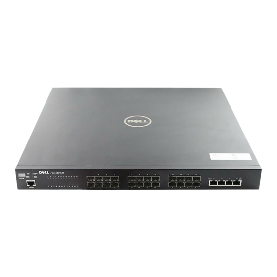
Chapter 1 S25P System Overview The Force10 Networks S25P (Cat# S25-01-GE-24P) is a high performance, low cost, stackable, Layer 2 switch/Layer 3 router that supports 24 SFP (small form-factor pluggable) ports, four built-in 10/100/1000 Base-T ports, and up to four 10-Gigabit (10GbE) ports (XFP or CX4), in two expansion slots. As highlighted in Figure 1, the front panel of the S25P contains a status panel that displays activity of the XFP... -
Page 10: Equipment
Equipment The following items are necessary to install the S25P system: • The switch • At least one grounded AC power source per S25P • One AC cable is included to connect the AC power source to the S25P (power cables are not supplied for the S25P-DC) •... -
Page 11: System Status
System Status S25P status can be derived in several ways, including physical LED displays and boot menu options, both discussed here, along with CLI commands,and SNMP traps. For details on those options, see the show Command Reference and Configuration Guide for your software (FTOS or SFTOS). LED Displays As shown in Figure... - Page 12 The following table describes the LED status indicators on the left side of the front panel. Table 4 Status Panel LED Display Label LED Color Description Left Side of the Status Panel Green Unit is online. Blinking Green Unit is booting up (blinking rate is 16 Hz). Amber Error during boot-up.
-
Page 13: Site Preparation
Chapter 2 Site Preparation This chapter describes requirements and procedures to install your S25P system, in the following topics: • Site Selection • Cabinet Placement on page 14 • Rack Mounting on page 14 • Fans and Airflow on page 14 •... -
Page 14: Cabinet Placement
Cabinet Placement The cabinet must meet the following criteria: • Minimum cabinet size and airflow are according to the EIA standard. • Minimum of 5 inches (12.7 cm) between the side intake and exhaust vents and the cabinet wall. Rack Mounting When you prepare your equipment rack, ensure that the rack is earth ground. -
Page 15: Power
Power The S25P comes standard with two AC power supplies acting in load-sharing mode; see Figure 2 on page 9. Use the power cords shipped with the S25P to connect it to AC power outlets, ideally on separate circuits. Several versions of the power cord are available, based on country requirements. The power supply cord is used as the main disconnect device;... -
Page 16: Tools Required
Tools Required S-Series switches are shipped fully assembled, encased in foam. A utility knife is useful for cutting the packing tape, and a Philips #2 screwdriver is required for attaching rack screws, and is also used for making some attachments, including DC cables and rear cover plates. Electrostatic discharge (ESD) damage can occur when components are mishandled. -
Page 17: Installing The S25P
Chapter 3 Installing the S25P To install the S25P system, Force10 Networks recommends that you complete the installation procedures in the order presented in this chapter: • Inserting Optional Modules (10-Gigabit or Stacking) • Installing the Switch on a Tabletop on page 19 •... - Page 18 To install a module, follow the steps below: Step Task If the switch is on, save the running configuration, if desired (and different from the startup configuration) with the command write memory. Then power down the system by unplugging it from its power source. Removing a module from a running system will lock up the switch, requiring a power Caution: cycle.
-
Page 19: Installing The Switch On A Tabletop
Installing the Switch on a Tabletop The S25P can be positioned on a stable tabletop. Four rubber standoffs are provided for that purpose in the plastic bag in the switch shipping box. Keep the following in mind when using a tabletop for your S25P: •... -
Page 20: Four-Post Rack-Mounting With Threaded Rails
Four-Post Rack-mounting with Threaded Rails Ensure that there is adequate clearance surrounding the cabinet or rack to permit access and airflow. If you are installing two S25P switches side-by-side, position the two S25P chassis at least 5 inches (12.7 cm) apart to permit proper airflow. - Page 21 Step Task Set the adjustable rear mounting bracket to the length (one of three lengths) for your bracket. Secure the length with the four screws. Figure 9 Four-post Rack-mounting with Threaded Rails . Installing the S25P System...
-
Page 22: Four-Post Rack-Mounting With Cage Nuts
Four-Post Rack-mounting with Cage Nuts Ensure that there is adequate clearance surrounding the cabinet or rack to permit access and airflow. If you are installing two S25P systems side-by-side, position them at least 5 inches (12.7 cm) apart. Follow the steps below to install the S25P chassis into a four-post rack mounting with cage nuts. - Page 23 Step Task Position the cage nuts over the holes on each bracket flange and each rack post. Figure 12 Four-Post Rack-mounting with Cage Nuts Align the rack filler panel to the rear bracket and rack posts. Secure by inserting two screws into the hole in the filler panel through to the holes in the rack post.
-
Page 24: Stacking
Stacking You can add units to a stack, remove them, renumber them, or move them in the stack. The units can continue running in the stack as you add new units, but new units should be powered down during the connection. -
Page 25: Using Ftos Stacking Commands
Using FTOS Stacking Commands While the S-Series hardware has built-in stacking controls, you can use FTOS to manage stacking, such as assign unit IDs, influence the management unit (master unit) selection algorithm, pre-configure a unit to be added to a stack, etc. The following commands provide a sample of that functionality: •... -
Page 26: Connecting Two Switches
While the diagram, above, shows A-B port connections, the ports are bi-directional, so you can connect A to A and/or B to B, as shown below in examples of two-switch (Figure 16 on page 26) and three-switch (Figure 17 on page 27) ring topologies. -
Page 27: Supplying Power
Connecting Three Switches Force10 recommends the ring topology, as outlined above (Figure 14 on page 25), for stacking S-Series switches, providing redundant connectivity. Using the example of three switches in the stack (Figure 16): Starting with the switch at the bottom of the stack, insert one end of the first cable into Stack Port A. Insert the other end of the first cable into Stack Port A of the middle switch. -
Page 28: S25P-Dc
Connect the supplied AC power cord first to either receptacle of the S25P (on the right as you face the rear of the chassis) and then to the power source (see Power Requirements on page 34). Ensure that the cord is secure. -
Page 29: Installing Ports
Chapter 4 Installing Ports This chapter contains these major sections: • Accessing the Console Port • Installing Optics on page 30 — Installing SFPs on page 31 — Installing XFPs on page 32 Accessing the Console Port Connect the RJ-45/DB-9 Figure 18 Console Port of S25P Set your initial console terminal settings adapter that is shipped with... -
Page 30: Installing Optics
Step Task (Continued) If necessary, connect the RJ-45/DB-9 adapter that is shipped with the S25P system to the end of the RJ-45 cable that will connect to your terminal. Verify your terminal default settings match the default settings, as listed above, on the console port: If you use the console port to download software to the switch, you will probably want to raise the console baud rate. -
Page 31: Installing Sfps
Installing SFPs Note: Starting with FTOS 7.8.1.0, when a copper SFP2 module with catalog number GP-SFP2-1T is used in the S25P switch, the SFP speed can be manually set with the speed command. When the speed is set to 10 or 100 Mbps, the duplex command can also be executed. -
Page 32: Installing Xfps
Installing XFPs To install an XFP into one of the two ports in the optional 10GbE optical module (see Inserting Optional Modules (10-Gigabit or Stacking) on page 17) on the back of the switch, follow the procedure below: Warning: Electrostatic discharge (ESD) damage can occur if components are mishandled. Always wear an ESD-preventive wrist or heel ground strap when handling the S25P and its components. -
Page 33: S25P Specifications
Chapter 5 S25P Specifications Chassis Physical Design Parameter Specifications Weight (chassis weight with factory-installed components) 14.41 pounds (approx.) (6.54 kg) Height 1.73 inches (4.4 cm) Width 17.32 inches (44 cm) (19" rack-mountable) Depth 16.73 inches (42.5 cm) (standard 1 rack unit – 1RU) Rack clearance required Front: 5-inches (12.7 cm) Rear: 5-inches (12.7 cm) -
Page 34: Power Requirements
Power Requirements Parameter Specifications Nominal Input Voltage S25P: 90 – 254 VAC, 47/63 Hz S25P-DC: -48 VDC Maximum Current Draw S25P: 2 A @ 100/120 VAC; 1 A @ 200/240 VAC S25P-DC: 3.6 A @ -48 VDC Minimum AC Current Draw .25 A @ 254 VAC .56 A @ 90 VAC Maximum Power Consumption... - Page 35 Networks cannot accept responsibility for any failure to satisfy the protection requirements resulting from a non-recommended modification of this product, including the fitting of non-Force10 option cards. This product has been tested and found to comply with the limits for Class A Information Technology Equipment according to CISPR 22/European Standard EN 55022.
-
Page 36: Safety Standards And Compliance Agency Certifications
Safety Standards and Compliance Agency Certifications • CUS UL (60950-1, 1st Edition) • CSA 60950-1-03, 1st Edition • IEC60950-1 1st Ed including all National Deviations and Group Differences • EN 60950-1, 1st Edition • EN 60825-1, 1st Edition • EN 60825-1 Safety of Laser Products—Part 1: Equipment Classification Requirements and User’s Guide •... - Page 37 Waste Electrical and Electronic Equipment (WEEE) Directive for Recovery, Recycle and Reuse of IT and Telecommunications Products Force10 switches are labeled in accordance with European Directive 2002/96/EC concerning waste electrical and electronic equipment (WEEE). The Directive determines the framework for the return and recycling of used appliances as applicable throughout the European Union.
- Page 38 Batteries or packaging for batteries are labeled in accordance with European Directive 2006/66/EC concerning batteries and accumulators and waste batteries and accumulators. The Directive determines the framework for the return and recycling of used batteries and accumulators as applicable throughout the European Union.
-
Page 39: Technical Support
Appendix A Technical Support This appendix contains these major sections: • The iSupport Website • Contacting the Technical Assistance Center on page 41 • Locating Serial Numbers on page 42 • Requesting a Hardware Replacement on page 43 The iSupport Website iSupport provides a range of documents and tools to assist you with effectively using Force10 equipment and mitigating the impact of network outages. -
Page 40: Accessing Isupport Services
Figure 23 Support Policies section of iSupport Figure 24 Support Policies section of iSupport The screenshot above shows the Support Policies section of iSupport. The Support Guide, available on that page, details the types of information and services that you can access through iSupport and through various types of support contracts. -
Page 41: Contacting The Technical Assistance Center
Contacting the Technical Assistance Center Log in to iSupport at http://www.force10networks.com/support/, and select the How to Contact Force10 Service Request tab. • Your name, company name, phone number, and E-mail address Information to Submit When Opening a Support • Preferred method of contact Case •... -
Page 42: Locating Serial Numbers
Locating Serial Numbers You can use the show switch unit command in the CLI to access the serial number of the designated switch ( unit = stack ID). The serial number of the chassis is located on a sticker on the back of the chassis in the middle. -
Page 43: Requesting A Hardware Replacement
Requesting a Hardware Replacement To request replacement hardware, follow these steps: Step Task Determine the part number and serial number of the component. To list the numbers for all components installed in the chassis, use the show hardware command. Request a Return Materials Authorization (RMA) number from TAC by opening a support case. Open a support case by: •... -
Page 45: Index
Index Numerics chassis height 10G module serial number Chassis Physical Design 10-Gigabit module depth 10-Gigabit module, inserting height 12G module width 24G module commands 24G stacking ports cx4-cable-length duplex lineconfig member AC power movemanagement AC Power Supply no member serial baudrate show logging eventlog acoustic noise show switch... - Page 46 Installation Cabinet Danger Rack DB-9 to RJ-45 Tabletop DC Power Supply iSupport depth of chassis jumbo frame support disposal, switch jumbo frames duplex command LED Displays earth ground LEDs, port status electromagnetic noise LEDs, stacking electrostatic discharge LEDs, Status indicator lineconfig command Emissions load-sharing...
- Page 47 AC requirements shock and vibration consumption show commands power cord show hardware command power receptacle show logging command power supply LED show logging eventlog command Power Supply module serial number show running-config command show switch command show switch unit command show system brief command rack clearance show system stack-ports command...
- Page 48 System Logs chapters System Status Table of Contents Tabletop Installation Technical Assistance Center (TAC), contacting temperature acceptable ambient range fans and ventilation relative humidity storage temperature warning message temperature, operating temperature, storage terminal server terminal settings, console Thermal Output, Maximum Tools Required topology cascade...