Table of Contents
Advertisement
Advertisement
Table of Contents

Related Manuals for Supermicro Supero H8SMi-2


Summary of Contents for Supermicro Supero H8SMi-2
- Page 1 ® UPER H8SMi-2 H8SMA-2 USER’S MANUAL Revision 1.0c...
- Page 2 Please Note: For the most up-to-date version of this manual, please see our web site at www.supermicro.com. Super Micro Computer, Inc. ("Supermicro") reserves the right to make changes to the product described in this manual at any time and without notice. This product, including software, if any, and documentation may not, in whole or in part, be copied, photocopied, reproduced, translated or reduced to any medium or machine without prior written consent.
-
Page 3: Manual Organization
MCP55 Pro chipset and supports single AMD Socket F type processors and up to 8 GB of DDR2-800/667/533 unbuffered ECC/non-ECC SDRAM. Please refer to the motherboard specifi cations pages on our web site for updates on supported processors (http://www.supermicro.com/aplus/). This product is intended to be professionally installed. Manual Organization Chapter 1 includes a checklist of what should be included in your motherboard box, describes the features, specifi... -
Page 4: Table Of Contents
About This Manual ...................... iii Manual Organization ....................iii Chapter 1: Introduction Overview ......................1-1 Checklist ....................1-1 Contacting Supermicro ................1-2 H8SMi-2 Image ..................1-3 H8SMi-2/H8SMA-2 Motherboard Layout ..........1-4 H8SMi-2/H8SMA-2 Quick Reference ............1-5 Motherboard Features ................1-6 nVidia MCP55 Pro Chipset: System Block Diagram ....... - Page 5 Table of Contents USB Headers ................... 2-9 Serial Ports ..................... 2-10 Fan Headers ..................2-10 LAN1/2 (Ethernet Ports) ................. 2-10 Power LED/Speaker ................2-11 Overheat LED ..................2-11 Chassis Intrusion ..................2-11 Wake-On-LAN ..................2-11 Wake-On-Ring ..................2-12 SMBus Header ..................2-12 Redundant Powerr Supply Fail Header ..........
- Page 6 H8SMi-2/H8SMA-2 User’s Manual No Power ....................3-1 No Video ....................3-1 Memory Errors ..................3-2 Losing the System’s Setup Confi guration ..........3-2 Technical Support Procedures ............... 3-2 Frequently Asked Questions ................3-3 Returning Merchandise for Service ..............3-4 Chapter 4: BIOS Introduction .....................
-
Page 7: Chapter 1: Introduction
Chapter 1: Introduction Chapter 1 Introduction Overview Checklist Congratulations on purchasing your computer motherboard from an acknowledged leader in the industry. Super Micro boards are designed with the utmost attention to detail to provide you with the highest standards in quality and performance. Please check that the following items have all been included with your motherboard. -
Page 8: Contacting Supermicro
Super Micro Computer, Inc. 980 Rock Ave. San Jose, CA 95131 U.S.A. Tel: +1 (408) 503-8000 Fax: +1 (408) 503-8008 Email: marketing@supermicro.com (General Information) support@supermicro.com (Technical Support) Web Site: www.supermicro.com Europe Address: Super Micro Computer B.V. Het Sterrenbeeld 28, 5215 ML... -
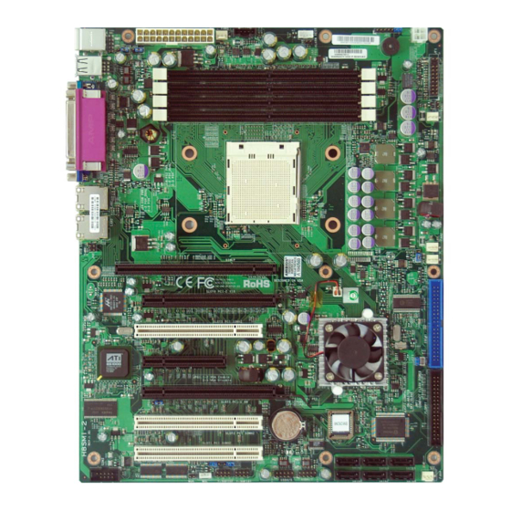
Page 9: H8Smi-2 Image
Chapter 1: Introduction Figure 1-1. H8SMi-2 Image See notes on following page for the differences between the H8SMi-2 and H8SMA-2. -
Page 10: H8Smi-2/H8Sma-2 Motherboard Layout
H8SMi-2/H8SMA-2 User’s Manual Figure 1-2. H8SMi-2/H8SMA-2 Motherboard Layout (not drawn to scale) JSMB1 JPW1 Kybd/ Mouse FAN5 Speaker JUSB1 DIMM 2B COM1 DIMM 1B DIMM 2A JOH1 DIMM 1A FAN1 Parallel Port LAN1 LAN2 FAN2 FAN3 SIMLP nFAN1 Slot #6: PCI-E x16 Slot #5: PCI 33 MHz nVidia MCP55 Pro... -
Page 11: H8Smi-2/H8Sma-2 Quick Reference
Chapter 1: Introduction H8SMi-2/H8SMA-2 Quick Reference Jumpers Description Default Setting PS2 Power Pins 1-2 (P5V Dual) USB Power Pins 1-2 (P5V Dual) JBT1 CMOS Clear See Section 2-7 JCF1 Compact Flash Master/Slave Closed (Master) C1/2 C to PCI Enable/Disable Closed (Enabled) JPG1* VGA Enable/Disable Pins 1-2 (Enabled) -
Page 12: Motherboard Features
H8SMi-2/H8SMA-2 User’s Manual Motherboard Features • Single AMD Socket AM2 for Dual-Core, Opteron 1000 series processor Note: Refer to our website for details on supported processors. Memory • Four dual/single channel DIMM slots supporting up to 8 GB of DDR2-800/667/533 unbuffered ECC/non-ECC SDRAM Note: Refer to Section 2-4 before installing DIMMs. - Page 13 Chapter 1: Introduction ACPI Features • Microsoft OnNow • Slow blinking LED for suspend state indicator • BIOS support for USB keyboard • Main switch override mechanism • Internal/external modem ring-on • Suspend to RAM (STR) Onboard I/O • On-chip SATA controller supporting six (6) SATA ports (RAID 0, 1, 0+1, 5 and JBOD supported) •...
-
Page 14: Nvidia Mcp55 Pro Chipset: System Block Diagram
H8SMi-2/H8SMA-2 User’s Manual 128-bit data + 16-bit ECC DDR2-800/667/533 DIMM 2B DIMM 1B AMD Socket AM2 DIMM 2A DIMM 1A 16 x 16 HT link (1 GHz) PCI-Exp Bus Slot 6: PCI-E x16 SATA Ports (6) Slot 4: PCI-E x4 nVidia IDE (ATA133) (1) Slot 3: PCI-E x8... -
Page 15: Chipset Overview
Chapter 1: Introduction Chipset Overview The H8SMi-2/H8SMA-2 motherboard is based on the nVidia MCP55 Pro chipset. The nVidia MCP55 Pro functions as Media and Communications Processor (MCP). Controllers for the system memory are integrated directly into AMD Opteron pro- cessors. MCP55 Pro Media and Communications Processor The MCP55 Pro is a single-chip, high-performance HyperTransport peripheral con- troller. -
Page 16: Pc Health Monitoring
H8SMi-2/H8SMA-2 User’s Manual PC Health Monitoring This section describes the PC health monitoring features of the H8SMi-2/H8SMA- 2. The motherboard has an onboard System Hardware Monitor chip that supports PC health monitoring. Onboard Voltage Monitors for CPU Core, 3.3V Vcc, +5Vin, +12Vin, 5V Standby and Battery Voltage The onboard voltage monitor will scan these voltages continuously. -
Page 17: Power Confi Guration Settings
Chapter 1: Introduction Power Confi guration Settings This section describes the features of your motherboard that deal with power and power settings. Microsoft OnNow The OnNow design initiative is a comprehensive, system-wide approach to system and device power control. OnNow is a term for a PC that is always on but appears to be off and responds immediately to user or other requests. -
Page 18: Power Supply
H8SMi-2/H8SMA-2 User’s Manual Wake-On-Ring Header (WOR) Wake-up events can be triggered by a device such as the external modem ringing when the system is in the SoftOff state. Note that external modem ring-on can only be used with an ATX 2.01 (or above) compliant power supply. Power Supply As with all computer products, a stable power source is necessary for proper and reliable operation. -
Page 19: Super I/O
Chapter 1: Introduction Super I/O The disk drive adapter functions of the Super I/O chip include a fl oppy disk drive controller that is compatible with industry standard 82077/765, a data separator, write pre-compensation circuitry, decode logic, data rate selection, a clock genera- tor, drive interface control logic and interrupt and DMA logic. - Page 20 H8SMi-2/H8SMA-2 User’s Manual Notes 1-14...
-
Page 21: Chapter 2: Installation
Chapter 2: Installation Chapter 2 Installation Static-Sensitive Devices Electrostatic Discharge (ESD) can damage electronic com ponents. To prevent dam- age to your system board, it is important to handle it very carefully. The following measures are generally suffi cient to protect your equipment from ESD. Precautions •... -
Page 22: Processor And Heatsink Installation
H8SMi-2/H8SMA-2 User's Manual Processor and Heatsink Installation Exercise extreme caution when handling and installing the proces- sor. Always connect the power cord last and always remove it be- fore adding, removing or changing any hardware components. Installing the CPU Backplates A CPU backplate (BKT-0017L) has been included in the retail box. - Page 23 Chapter 2: Installation 4. With the CPU inserted into the socket, inspect the four corners of the CPU to make sure that it is properly installed and fl ush with the socket. 5. Gently press the CPU socket lever down until it locks in the plastic tab. For a dual-processor system, repeat these steps to install another CPU into the CPU#2 socket.
-
Page 24: Mounting The Motherboard Into A Chassis
H8SMi-2/H8SMA-2 User's Manual Mounting the Motherboard into a Chassis All motherboards have standard mounting holes to fi t different types of chassis. Make sure that the locations of all the mounting holes for both the motherboard and the chassis match. Although a chassis may have both plastic and metal mounting fasteners, metal ones are highly recommended because they ground the motherboard to the chassis. - Page 25 Chapter 2: Installation Support The H8SMi-2/H8SMA-2 supports single or dual-channel, DDR2-800/667/533 unbuf- fered ECC/non-ECC SDRAM. Both interleaved and non-interleaved memory are supported, so you may populate any number of DIMM slots (see note on previous page). Populating two adjacent slots at a time with memory modules of the same size and type will result in interleaved (128-bit) memory, which is faster than non-interleaved (64-bit) memory.
-
Page 26: I/O Port And Control Panel Connections
H8SMi-2/H8SMA-2 User's Manual I/O Port and Control Panel Connections The I/O ports are color coded in conformance with the PC99 specifi cation to make setting up your system easier. See Figure 2-3 below for the colors and locations of the various I/O ports. Figure 2-3. -
Page 27: Connector Defi Nitions
Chapter 2: Installation Connector Defi nitions ATX Power 24-pin Connector Pin Defi nitions (J1B1) ATX Power Connector Pin# Defi nition Pin # Defi nition +3.3V +3.3V The primary ATX power supply con- -12V +3.3V nector (J1B1) meets the SSI (Super- set ATX) 24-pin specifi... -
Page 28: Nic1 Led
H8SMi-2/H8SMA-2 User's Manual NIC1 LED NIC1 LED The NIC1 (Network Interface Control- Pin Defi nitions (JF1) ler) LED connection is located on pins Pin# Defi nition 11 and 12 of JF1. Attach the NIC1 LED cable to display network activity. NIC1 Active Refer to the table on the right for pin defi... -
Page 29: Power Button
Chapter 2: Installation Power Button The Power Button connection is located on pins 1 and 2 of JF1. Mo- mentarily contacting both pins will Power Button Pin Defi nitions (JF1) power on/off the system. This button Pin# Defi nition can also be confi gured to function as a suspend button (see the Power PW_ON Button Mode setting in BIOS). -
Page 30: Serial Ports
H8SMi-2/H8SMA-2 User's Manual ATX PS/2 Keyboard and PS/2 Keyboard and Mouse Port Pin PS/2 Mouse Ports Defi nitions Pin# Defi nition The ATX PS/2 keyboard and the Data PS/2 mouse ports are located on the IO backplane. The mouse is the top Ground (green) port. -
Page 31: Power Led/Speaker
Chapter 2: Installation Power LED/Speaker PWR LED Connector Pin Defi nitions (JD1) Pin# Defi nition On JD1, pins 1, 2, and 3 are for the +Vcc power LED and pins 4 through 7 are for the speaker. See the tables on the Control right for pin defi... -
Page 32: Wake-On-Ring
H8SMi-2/H8SMA-2 User's Manual Wake-On-Ring The Wake-On-Ring header is desig- Wake-On-Ring Pin Defi nitions (WOR) nated WOR. This function allows your Pin# Defi nition computer to receive and "wake-up" by Ground (Black) an incoming call to the modem when Wake-up in suspend state. See the table on the right for pin defi... -
Page 33: Power Fail Alarm Reset Header
Chapter 2: Installation Power Fail Alarm Reset Alarm Reset Header Header Pin Defi nitions (JAR) Pin# Defi nition Connect JAR to the alarm reset but- Ground ton on your chassis (if available) or to Reset Signal a microswitch to allow you to turn off the alarm that sounds when a power supply module fails. -
Page 34: Jumper Settings
H8SMi-2/H8SMA-2 User's Manual Jumper Settings Explanation of Jumpers To modify the operation of the Connector motherboard, jumpers can be Pins used to choose between optional settings. Jumpers create shorts between two pins to change the Jumper function of the connector. Pin 1 is identifi... -
Page 35: Vga Enable/Disable
Chapter 2: Installation VGA Enable/Disable VGA Enable/Disable Jumper Settings (JPG1) JPG1 allows you to enable or disable the VGA port. The default position is Jumper Setting Defi nition on pins 1 and 2 to enable VGA. See Pins 1-2 Enabled the table on the right for jumper set- Pins 2-3 Disabled... -
Page 36: Onboard Speaker Enable/Disable
H8SMi-2/H8SMA-2 User's Manual Onboard Speaker Enable/ Disable Onboard Speaker Enable/Disable The JD1 header allows you to use Pin Defi nitions (JD1) either an external speaker or the in- Pins Defi nition ternal (onboard) speaker. To use the 6 and 7 Jump for onboard speaker internal onboard speaker, close pins 4 and 7... -
Page 37: Onboard Indicators
Chapter 2: Installation Onboard Indicators LAN1/LAN2 LEDs LAN LED (Connection Speed Indicator) The Ethernet ports (located beside LED Color Defi nition the VGA port) have two LEDs. On 10 MHz each Gb LAN port, one LED blinks to Green 100 MHz indicate activity while the other may Amber 1 GHz... -
Page 38: Floppy, Ide, Parallel Port And Sata Drive Connections
H8SMi-2/H8SMA-2 User's Manual Floppy, IDE, Parallel Port and SATA Drive Connections Use the following information to connect the fl oppy and hard disk drive cables. The fl oppy disk drive cable has seven twisted wires. A red mark on a wire typically designates the location of pin 1. A single fl... -
Page 39: Ide Connectors
Chapter 2: Installation IDE Connector IDE Drive Connector Pin Defi nitions (IDE#1) Pin# Defi nition Pin # Defi nition There are no jumpers to con- fi gure the onboard IDE#1 con- Reset IDE Ground nector unless using it for a Host Data 7 Host Data 8 compact flash device. -
Page 40: Parallel Port
H8SMi-2/H8SMA-2 User's Manual Parallel Port The parallel port is located on the I/O backplane. See the table below for pin defi nitions. Parallel (Printer) Port Pin Defi nitions Pin# Defi nition Pin # Defi nition Strobe- Auto Feed- Data Bit 0 Error- Data Bit 1 Init-... -
Page 41: 2-10 Enabling Sata Raid
OS installation. Building a Driver Diskette You must fi rst build a driver diskette from the Supermicro CD-ROM that was included with the system. (You will have to create this disk on a computer that is already running and with the OS installed.) Insert the CD into your CD-ROM drive and... - Page 42 H8SMi-2/H8SMA-2 User's Manual 2. Use the arrow keys to move to the "Advanced" menu, then scroll down to "nVidia RAID Setup" and press the <Enter> key. Once in the submenu, scroll down to "nVidia RAID Function" and enable the setting, which will cause the SATA0/1/2 Primary/Secondary settings to appear.
-
Page 43: 2-11 Installing Drivers
Chapter 2: Installation 2-11 Installing Drivers The CD that came bundled with the system contains software drivers, some of which must be installed, such as the chipset driver. After inserting this CD into your CD- ROM drive, the display shown in Figure 2-5 should appear. (If this display does not appear, click on the My Computer icon and then on the icon representing your CD-ROM drive. - Page 44 H8SMi-2/H8SMA-2 User's Manual Notes 2-24...
-
Page 45: Chapter 3: Troubleshooting
Chapter 3: Troubleshooting Chapter 3 Troubleshooting Troubleshooting Procedures Use the following procedures to troubleshoot your system. If you have followed all of the procedures below and still need assistance, refer to the ‘Technical Support Procedures’ and/or ‘Returning Merchandise for Service’ section(s) in this chapter. Always disconnect the AC power cord before adding, changing or installing any hardware components. -
Page 46: Memory Errors
H8SMi-2/H8SMA-2 User's Manual NOTE If you are a system integrator, VAR or OEM, a POST diagnostics card is recommended. For I/O port 80h codes, refer to App. B. Memory Errors 1. Make sure that the DIMM modules are properly and fully installed. 2. -
Page 47: Frequently Asked Questions
Chapter 3: Troubleshooting 3. If you still cannot resolve the problem, include the following information when contacting us for technical support: Motherboard model and PCB revision number BIOS release date/version (this can be seen on the initial display when your system fi... -
Page 48: Returning Merchandise For Service
For faster service, RMA authorizations may be requested online (http://www. supermicro.com/support/rma/). This warranty only covers normal consumer use and does not cover damages in- curred in shipping or from failure due to the alteration, misuse, abuse or improper maintenance of products. -
Page 49: Chapter 4: Bios
Chapter 4: BIOS Chapter 4 BIOS Introduction This chapter describes the AMIBIOS™ Setup utility for the H8SMi-2/H8SMA-2. The AMI ROM BIOS is stored in a fl ash chip and can be easily upgraded using a fl oppy disk-based program. Note: Due to periodic changes to the BIOS, some settings may have been added or deleted and might not yet be recorded in this manual. -
Page 50: Main Menu
H8SMi-2/H8SMA-2 User’s Manual Main Menu When you fi rst enter AMI BIOS Setup Utility, you will see the Main Menu screen. You can always return to the Main Menu by selecting the Main tab on the top of the screen with the arrow keys. The Main Menu screen provides you with a system overview, which includes the version, built date and ID of the AMIBIOS, the type, speed and number of the processors in the system and the amount of memory installed in the system. - Page 51 Chapter 4: BIOS PS/2 Mouse Support Set this value to allow the PS/2 mouse support to be modifi ed. The options are Enabled, Disabled and Auto. Wait for ‘F1’ If Error Select Enabled to activate the function of Wait for "F1" if Error. T Hit ‘DEL’...
- Page 52 H8SMi-2/H8SMA-2 User’s Manual Power Confi guration Power Button Mode Allows the user to change the function of the power button. Options are On/Off and Suspend. Restore on AC Power Loss This setting allows you to choose how the system will react when power returns after an unexpected loss of power.
- Page 53 Chapter 4: BIOS Floppy/IDE/SATA Confi guration Floppy A Move the cursor to these fi elds via up and down <arrow> keys to select the fl oppy type. The options are Disabled, 360 KB 5 1/4", 1.2 MB 5 1/4", 720 KB 3½", 1.44 MB 3½”, and 2.88 MB 3½".
- Page 54 H8SMi-2/H8SMA-2 User’s Manual Primary IDE Master/Slave Highlight one of the items above and press <Enter> to access the submenu for that item. Type Select the type of device connected to the system. The options are Not Installed, Auto, CDROM and ARMD. LBA/Large Mode LBA (Logical Block Addressing) is a method of addressing data on a disk drive.
- Page 55 Chapter 4: BIOS DMA Mode Selects the DMA Mode. Options are Auto, SWDMA0, SWDMA1, SWDMA2, MWDMA0. MDWDMA1, MWDMA2, UDMA0. UDMA1, UDMA2, UDMA3, UDMA4 and UDMA5. (SWDMA=Single Word DMA, MWDMA=Multi Word DMA, UDMA=UltraDMA.) S.M.A.R.T. Self-Monitoring Analysis and Reporting Technology (SMART) can help predict impending drive failures.
- Page 56 H8SMi-2/H8SMA-2 User’s Manual cannot be determined. Select 0 to allow AMI BIOS to use PIO mode 0. It has a data transfer rate of 3.3 MBs. Select 1 to allow AMI BIOS to use PIO mode 1. It has a data transfer rate of 5.2 MBs. Select 2 to allow AMI BIOS to use PIO mode 2.
- Page 57 Chapter 4: BIOS PCI/PnP Confi guration Clear NVRAM Select Yes to clear NVRAM during boot-up. The options are Yes and No. Plug & Play OS Select Yes to allow the OS to confi gure Plug & Play devices. (This is not required for system boot if your system has an OS that supports Plug &...
- Page 58 H8SMi-2/H8SMA-2 User’s Manual IRQ3/IRQ4/IRQ5/IRQ7/IRQ9/IRQ10/IRQ11/IRQ14/IRQ15 This feature specifi es the availability of an IRQ to be used by a PCI/PnP device. Select Reserved for the IRQ to be used by a Legacy ISA device. The options are Available and Reserved. DMA Channel 0/Channel 1/Channel 3/Channel 5/Channel 6/Channel Select Available to indicate that a specifi...
- Page 59 Chapter 4: BIOS Parallel Port Mode Specify the parallel port mode. The options are Normal, Bi-directional, EPP and ECP. Parallel Port IRQ Select the IRQ (interrupt request) for the parallel port. The options are IRQ5 and IRQ7. Advanced Chipset Confi guration NorthBridge Confi...
- Page 60 H8SMi-2/H8SMA-2 User’s Manual ECC Confi guration DRAM ECC Enable DRAM ECC allows hardware to report and correct memory errors automati- cally. Options are Enabled and Disabled. 4-Bit ECC Mode Allows the user to enabled 4-bit ECC mode (also known as ECC Chip- kill).
- Page 61 Chapter 4: BIOS possibility of Electromagnetic Interference. PCIE Spread Spectrum Use this setting to Enable or Disable spread spectrum for the PCIE. SATA Spread Spectrum Use this setting to Enable or Disable spread spectrum for SATA. Primary Graphics Adapter Use this setting to select PCI Express -> PCI or PCI -> PCI Express for the primary graphics adapter.
- Page 62 H8SMi-2/H8SMA-2 User’s Manual MAC1 LAN1 Bridge Settings are Enabled and Disabled for MAC1 LAN1 bridge. Event Log Confi guration View Event Log Highlight this item and press <Enter> to view the contents of the event log. Mark All Events as Read Highlight this item and press <Enter>...
-
Page 63: System Health Monitor
Chapter 4: BIOS Redirection After BIOS POST Options are Disable (no redirection after BIOS POST), Boot Loader (redirection during POST and during boot loader) and Always (redirection always active). Note that some OS's may not work with this set to Always. Terminal Type Selects the type of the target terminal. - Page 64 H8SMi-2/H8SMA-2 User’s Manual Other items in the submenu are system monitor displays for the following infor- mation: CPU Temperature, System Temperature, CPU1 VCore, 3.3V Vcc (V), +5Vin, +12Vin, 5V Standby and Battery Voltage. View BMC System Event Log Pressing the Enter key will open the event log. Use the "+" and "-" keys to navigate through the system event log.
-
Page 65: Boot Menu
Chapter 4: BIOS Boot Menu This feature allows the user to confi gure the following items: Boot Device Priority This feature allows the user to prioritize the boot sequence from the available de- vices. The devices to set are: · 1st Boot Device ·... -
Page 66: Security Menu
H8SMi-2/H8SMA-2 User’s Manual Security Menu AMI BIOS provides a Supervisor and a User password. If you use both passwords, the Supervisor password must be set fi rst. Change Supervisor Password Select this option and press <Enter> to access the sub menu, and then type in the password. - Page 67 Chapter 4: BIOS Load Optimal Defaults To set this feature, select Load Optimal Defaults from the Exit menu and press <Enter>. Then Select "OK" to allow BIOS to automatically load the Optimal Defaults as the BIOS Settings. The Optimal settings are designed for maximum system performance, but may not work best for all computer applications.
- Page 68 H8SMi-2/H8SMA-2 User’s Manual Notes 4-20...
-
Page 69: Appendix A: Bios Error Beep Codes
Appendix A: BIOS Error Beep Codes Appendix A BIOS Error Beep Codes During the POST (Power-On Self-Test) routines, which are performed each time the system is powered on, errors may occur. Non-fatal errors are those which, in most cases, allow the system to continue the boot-up process. - Page 70 H8SMi-2/H8SMA-2 User’s Manual Notes...
-
Page 71: Appendix B: Bios Post Checkpoint Codes
Appendix B: BIOS POST Checkpoint Codes Appendix B BIOS POST Checkpoint Codes When AMIBIOS performs the Power On Self Test, it writes checkpoint codes to I/O port 0080h. If the computer cannot complete the boot process, diagnostic equipment can be attached to the computer to read I/O port 0080h. Uncompressed Initialization Codes The uncompressed initialization checkpoint codes are listed in order of execution: Checkpoint... - Page 72 H8SMi-2/H8SMA-2 User’s Manual Bootblock Recovery Codes The bootblock recovery checkpoint codes are listed in order of execution: Checkpoint Code Description The onboard fl oppy controller if available is initialized. Next, beginning the base 512 KB memory test. Initializing the interrupt vector table next. Initializing the DMA and Interrupt controllers next.
- Page 73 Appendix B: BIOS POST Checkpoint Codes Uncompressed Initialization Codes The following runtime checkpoint codes are listed in order of execution. These codes are uncompressed in F0000h shadow RAM. Checkpoint Code Description The NMI is disabled. Next, checking for a soft reset or a power on condition. The BIOS stack has been built.
- Page 74 H8SMi-2/H8SMA-2 User’s Manual Checkpoint Code Description Interrupt vector initialization is done. Clearing the password if the POST DIAG switch is on. Any initialization before setting video mode will be done next. Initialization before setting the video mode is complete. Confi guring the mono- chrome mode and color mode settings next.
- Page 75 Appendix B: BIOS POST Checkpoint Codes Checkpoint Code Description The memory below 1 MB has been cleared via a soft reset. Clearing the memory above 1 MB next. The memory above 1 MB has been cleared via a soft reset. Saving the memory size next.
- Page 76 H8SMi-2/H8SMA-2 User’s Manual Checkpoint Code Description The password was checked. Performing any required programming before WIN- BIOS Setup next. The programming before WINBIOS Setup has completed. Uncompressing the WINBIOS Setup code and executing the AMIBIOS Setup or WINBIOS Setup utility next.
- Page 77 Appendix B: BIOS POST Checkpoint Codes Checkpoint Code Description Returned from adaptor ROM at E000h control. Performing any initialization required after the E000 option ROM had control next. Initialization after E000 option ROM control has completed. Displaying the system confi guration next. Uncompressing the DMI data and executing DMI POST initialization next.
- Page 78 H8SMi-2/H8SMA-2 User’s Manual Notes...