Table of Contents
Advertisement
Quick Links
FortiGate – 4000
KVM/ACCESS
KVM/ACCESS
KVM ACCESS
KVM/ACCESS
KVM/ACCESS
PWR/KVM STATUS
PWR/KVM STATUS
PWR/KVM STATUS
PWR/KVM STATUS
PWR/KVM STATUS
LAN 1
LAN 2
LAN 1
LAN 2
LAN 1
LAN 2
LAN 1
LAN 2
LAN 1
LAN 2
POWER ON/OFF
POWER ON/OFF
POWER ON/OFF
POWER ON/OFF
POWER ON/OFF
FortiGate User Manual Volume 1
Version 2.50
February 5 2004
User Manual
KVM/ACCESS
KVM/ACCESS
KVM/ACCESS
KVM/ACCESS
KVM/ACCESS
PWR/KVM STATUS
PWR/KVM STATUS
PWR/KVM STATUS
PWR/KVM STATUS
PWR/KVM STATUS
LAN 1
LAN 2
LAN 1
LAN 2
LAN 1
LAN 2
LAN 1
LAN 2
LAN 1
LAN 2
POWER ON/OFF
POWER ON/OFF
POWER ON/OFF
POWER ON/OFF
POWER ON/OFF
ALARM
KVM
Advertisement
Table of Contents

Related Manuals for Fortinet FortiGate 4000


Summary of Contents for Fortinet FortiGate 4000
-
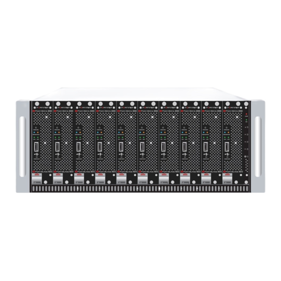
Page 1: User Manual
FortiGate – 4000 KVM/ACCESS PWR/KVM STATUS LAN 1 LAN 2 POWER ON/OFF KVM/ACCESS KVM ACCESS KVM/ACCESS KVM/ACCESS KVM/ACCESS KVM/ACCESS KVM/ACCESS PWR/KVM STATUS PWR/KVM STATUS PWR/KVM STATUS PWR/KVM STATUS PWR/KVM STATUS PWR/KVM STATUS PWR/KVM STATUS LAN 1 LAN 2 LAN 1 LAN 2 LAN 1 LAN 2... - Page 2 CAUTION: RISK OF EXPLOSION IF BATTERY IS REPLACED BY AN INCORRECT TYPE. DISPOSE OF USED BATTERIES ACCORDING TO THE INSTRUCTIONS. For technical support, please visit http://www.fortinet.com. Send information about errors or omissions in this document or any Fortinet technical documentation to techdoc@fortinet.com.
-
Page 3: Table Of Contents
Command line interface ... 21 Logging and reporting ... 21 Document conventions ... 21 Fortinet documentation ... 22 Comments on Fortinet technical documentation... 23 Customer service and technical support... 23 Getting started ... 25 Warnings and cautions ... 26 Warning... 26 Package contents ... - Page 4 Hot swapping the 10/100 out of band management module ... 43 Hot swapping the management module ... 44 Hot swapping the KVM switch module... 44 Connecting to the web-based manager ... 44 Connecting to the FortiGate-4000 internal interface module ... 45 Connecting to the FortiGate-4000 10/100 out of band management module ...
- Page 5 Using the command line interface... 64 Configuring the FortiGate unit to operate in NAT/Route mode ... 64 Configuring the out of band management interface ... 65 Connecting the FortiGate unit to your networks... 65 Configuring your networks ... 66 Completing the configuration ... 66 Configuring the out of band management interface ...
- Page 6 Backing up system settings ... 115 Restoring system settings... 116 Restoring system settings to factory defaults ... 116 Changing to Transparent mode ... 117 Changing to NAT/Route mode... 117 Restarting the FortiGate unit... 118 Shutting down the FortiGate unit ... 118 Fortinet Inc.
- Page 7 FortiCare Service Contracts... 134 Registering the FortiGate unit ... 134 Updating registration information ... 136 Recovering a lost Fortinet support password... 136 Viewing the list of registered FortiGate units ... 137 Registering a new FortiGate unit ... 137 Adding or changing a FortiCare Support Contract number... 138 Changing your Fortinet support password ...
- Page 8 Adding destination-based routes to the routing table... 159 Adding routes in Transparent mode... 160 Configuring the routing table... 161 Policy routing ... 161 Configuring DHCP services ... 162 Configuring a DHCP relay agent... 163 Configuring a DHCP server ... 163 Fortinet Inc.
- Page 9 Configuring the FortiGate unit for SNMP monitoring ... 180 Configuring FortiGate SNMP support ... 180 FortiGate MIBs... 182 FortiGate traps ... 183 Fortinet MIB fields ... 185 Replacement messages ... 187 Customizing replacement messages ... 188 Customizing alert emails... 189 Firewall configuration...
- Page 10 Adding user names and configuring authentication ... 228 Adding user names and configuring authentication ... 228 Deleting user names from the internal database ... 229 Configuring RADIUS support ... 230 Adding RADIUS servers ... 230 Deleting RADIUS servers ... 230 Fortinet Inc.
- Page 11 Configuring LDAP support ... 231 Adding LDAP servers... 231 Deleting LDAP servers... 232 Configuring user groups... 232 Adding user groups... 233 Deleting user groups... 234 IPSec VPN... 235 Key management... 236 Manual Keys ... 236 Automatic Internet Key Exchange (AutoIKE) with pre-shared keys or certificates ... 236 Manual key IPSec VPNs...
- Page 12 Configuring FortiGate Web URL blocking ... 291 Configuring FortiGate Web pattern blocking... 294 Configuring Cerberian URL filtering ... 294 Installing a Cerberian license key ... 295 Adding a Cerberian user ... 295 Configuring Cerberian web filter ... 295 Enabling Cerberian URL filtering ... 296 Fortinet Inc.
- Page 13 Script filtering ... 297 Enabling script filtering... 297 Selecting script filter options ... 297 Exempt URL list ... 298 Adding URLs to the URL Exempt list ... 298 Downloading the URL Exempt List ... 299 Uploading a URL Exempt List... 299 Email filter...
- Page 14 Contents Fortinet Inc.
-
Page 15: Introduction
• • The FortiGate Antivirus Firewall uses Fortinet’s Accelerated Behavior and Content Analysis System (ABACAS™) technology, which leverages breakthroughs in chip design, networking, security, and content analysis. The unique ASIC-based architecture analyzes content and behavior in real-time, enabling key applications to be deployed right at the network edge, where they are most effective at protecting your networks. -
Page 16: Antivirus Protection
PKZip format, detect viruses in email that has been encoded using uuencode format, detect viruses in email that has been encoded using MIME encoding, log all actions taken while scanning. Introduction Fortinet Inc. -
Page 17: Email Filtering
Introduction Email filtering FortiGate email filtering can scan all IMAP and POP3 email content for unwanted senders or unwanted content. If there is a match between a sender address pattern on the email block list, or an email contains a word or phrase in the banned word list, the FortiGate adds an email tag to the subject line of the email. -
Page 18: Nat/Route Mode
To notify system administrators of the attack, the NIDS records the attack and any suspicious traffic to the attack log, and can be configured to send alert emails. Fortinet updates NIDS attack definitions periodically. You can download and install updated attack definitions manually or you can configure the FortiGate unit to automatically check for and download attack definition updates. -
Page 19: Vpn
• • High availability High Availability (HA) provides failover between two or more FortiGate units. Fortinet achieves HA by using redundant hardware: matching FortiGate models running in NAT/Route mode. You can configure the FortiGate units for either active-passive (A-P) or active-active (A-A) HA. -
Page 20: Secure Installation, Configuration, And Management
Once you are satisfied with a configuration, you can download and save it. The saved configuration can be restored at any time. Figure 1: The FortiGate web-based manager and setup wizard Introduction Fortinet Inc. -
Page 21: Command Line Interface
Introduction Command line interface You can access the FortiGate command line interface (CLI) by connecting a management computer serial port to the FortiGate RS-232 serial console connector. You can also use Telnet or a secure SSH connection to connect to the CLI from any network that is connected to the FortiGate unit, including the Internet. -
Page 22: Fortinet Documentation
Contains in-depth information about FortiGate IPSec VPN using certificates, pre- shared keys and manual keys for encryption. Also contains basic configuration information for the Fortinet Remote VPN Client, detailed configuration information for FortiGate PPTP and L2TP VPN, and VPN configuration examples. -
Page 23: Comments On Fortinet Technical Documentation
The FortiGate online help also contains procedures for using the FortiGate web-based manager to configure and manage the FortiGate unit. Comments on Fortinet technical documentation You can send information about errors or omissions in this document, or any Fortinet technical documentation, to techdoc@fortinet.com. Customer service and technical support... - Page 24 Customer service and technical support Introduction Fortinet Inc.
-
Page 25: Getting Started
FortiGate-4000 Installation and Configuration Guide Version 2.50 Getting started This chapter describes unpacking, setting up, and powering on a FortiGate-4000 Antivirus Firewall. When you have completed the procedures in this chapter, you can proceed to one of the following: • •... -
Page 26: Warnings And Cautions
One 10/100 out of band management module (rear panel). Three power cables, One RJ-45 to DB-9 serial cable (only the black header works with the FortiGate-4000 unit), One mounting rail kit, One FortiGate-4000 QuickStart Guide, One documentation CD containing Fortinet user documentation. Getting started Fortinet Inc. -
Page 27: Physical Description
LAN 4 LAN 3 LAN 2 LAN 1 FortiGate-4000P Chassis (back view) FortiGate-4000 ALARM QuickStart Guide Copyright 2003 Fortinet Incorporated. All rights reserved. Trademarks Products mentioned in this document are trademarks. LAN 2 LAN 1 ON OFF HiGig OUT HiGig IN... -
Page 28: Front Panel Features
FortiBlade-4010 modules ALARM KVM/ACCESS KVM/ACCESS KVM/ACCESS PWR/KVM STATUS PWR/KVM STATUS PWR/KVM STATUS LAN 1 LAN 2 LAN 1 LAN 2 LAN 1 LAN 2 POWER ON/OFF POWER ON/OFF POWER ON/OFF KVM switch module FortiGate-4000 empty slot cover Getting started Fortinet Inc. -
Page 29: Fortiblade-4010 Module
Getting started FortiBlade-4010 module Each FortiBlade-4010 module is an independent FortiGate-4000 antivirus firewall capable of operating at gigabit network speeds. You can install up to 10 FortiBlade-4010 modules in the FortiGate-4000 chassis. Each FortiBlade-4010 module can operate as a standalone FortiGate-4000 antivirus firewall or you can group FortiBlade-4010 modules into high availability (HA) clusters. -
Page 30: Kvm Switch Module
LAN 2 KVM switch module Use the KVM switch module to switch serial connections to the CLI of each FortiBlade-4010 module installed in the FortiGate-4000 chassis. To access the CLI, connect the the black header of the RJ-45 to DB-9 serial cable to the management... -
Page 31: Rear Panel Features
• • Figure 6: FortiGate-4000P rear panel Internal ethernet interface module FortiGate-4000 Installation and Configuration Guide Description Use these buttons to switch console access to each FortiBlade-4010 module. State Description Normal operation. FortiGate-4000 Green KVM switch module is powered on. -
Page 32: Power Supplies And Power Connections
Vac auto range. The power connections supply AC power to the power supplies. Connect the three power connections to three separate power outlets. Use the power switch on the power connector module to turn the FortiGate-4000 chassis power on and off. -
Page 33: Cooling Fan Trays
Figure 9: Cooling fan tray Management module Use the KVM switch module to switch serial connections to the CLI of each FortiBlade-4010 module installed in the FortiGate-4000 chassis. To access the CLI, connect the black header of the RJ-45 to DB-9 serial cable to the management module and to a management PC. -
Page 34: 10/100 Out Of Band Management Module
CLI of each FortiBlade-4010 module. Set to 0. Serial connection to the CLI of each FortiBlade-4010 module. State Description Normal operation. Yellow System fault. Contact Fortinet Technical Support. LAN 2 LAN 1 LAN 1 LAN 2 State Description... -
Page 35: Pass-Through Interface Module
Getting started Pass-through interface module Two pass-through interface modules are installed on the FortiGate-4000P. The internal pass-through interface module connects to each FortiBlade-4010 internal interface. The external pass-through interface connects to each FortiBlade-4010 external interface. Each pass-through interface module contains ten gigabit copper 1000Base-T ethernet interfaces, one for each FortiBlade-4010 module. -
Page 36: Switched Interface Module
The correct cable is in use and the connected equipment has power. Flashing Network activity at this interface. Amber Green The interface is connected at up to 1000 Mbps. Green System fault. Contact Fortinet technical support. Getting started On/off not used switch ON OFF HiGig IN Mounting Knot Status Fortinet Inc. -
Page 37: Installing Hardware
Getting started Installing hardware This section describes how to install FortiGate-4000 hardware. • • • • • • • • Choosing a suitable environment Considering the following factors when selecting a suitable location for the FortiGate-4000 unit: • • • •... -
Page 38: Installing Fortiblade-4010 Modules
Figure 15: Inserting the FortiBlade-4010 module into the chassis Slide the FortiBlade-4010 module into the slot until the lock clicks into place. Tighten the mounting knots both at the top and bottom of the front panel of the FortiBlade-4010 module. for slot numbering). Figure Getting started Fortinet Inc. -
Page 39: Fortigate-4000P Network Connections
Getting started FortiGate-4000P network connections Use the following steps to connect your internal and external networks to the FortiGate-4000P pass-through interface modules that support 1000Base-T connections. This is a general connection procedure only. For information about how to connect the FortiGate-4000 unit for different network configurations, see the FortiGate configuration”... -
Page 40: Out Of Band Management Connections
FortiBlade-4010 modules installed in the FortiGate-4000 chassis. Use the KVM switch module to switch serial connections to the CLI of each FortiBlade-4010 module installed in the FortiGate-4000 chassis. To access the CLI, connect the black header of the RJ-45 to DB-9 serial cable to the management... -
Page 41: Turning Off Fortigate-4000 Chassis Power
Connect the power cables to power outlets. Turn on the power switch on each power supply module. Press and hold the chassis power switch for a few seconds to turn it on to supply power to the power supplies. The Power LED on each power supply module lights. -
Page 42: Hot Swapping Fortiblade-4010 Modules
Pull out the power supply module by the handle. Holding the new power supply module by the handle, insert it into the chassis. “FortiBlade-4010 module” on page for more information. “Rear panel features” on page “Cooling fan trays” on Figure 8 on page Getting started Fortinet Inc. -
Page 43: Hot Swapping Interface Modules
Replace the locking strip. Quickly toggle the chassis power supply switch to turn on the power supply module. Note: If you press the chassis power supply switch for more than four seconds, the entire FortiGate-4000 unit turns off. Hot swapping interface modules This procedure describes how to hot swap a pass-through interface module or a switched interface module. -
Page 44: Hot Swapping The Management Module
Pull out the KVM switch module. Insert the new KVM switch module into the chassis. Tighten the two mounting knots to fasten the KVM switch module to the chassis. Connecting to the web-based manager You can connect to the FortiGate-4000 web-based manager of each FortiGate-4000... -
Page 45: Connecting To The Fortigate-4000 Internal Interface Module
The Register Now window is displayed. Use the information in this window to register your FortiGate unit so that Fortinet can contact you for firmware updates. You must also register to receive updates to the FortiGate virus and attack definitions. -
Page 46: Connecting To The Fortigate-4000 10/100 Out Of Band Management Module
The Register Now window is displayed. Use the information in this window to register your FortiGate unit so that Fortinet can contact you for firmware updates. You must also register to receive updates to the FortiGate virus and attack definitions. -
Page 47: Connecting To The Command Line Interface (Cli)
Connecting to the Command Line Interface (CLI) Connect to the CLI of each FortiGate-4000 unit by connecting to the management interface module. Use the KVM switch module to switch serial connections to the CLI of each FortiGate-4000 unit installed in the FortiGate-4000 chassis. See... -
Page 48: Factory Default Configuration
IP addresses, add DNS server IP addresses, and configure routing, if required. If you plan to operate the FortiGate-4000 unit in Transparent mode, you can switch to Transparent mode from the factory default configuration and then configure the FortiGate-4000 unit onto the network in Transparent mode. -
Page 49: Factory Default Transparent Mode Network Configuration
Internal interface External interface Out of Band interface Factory default Transparent mode network configuration If you switch the FortiGate-4000 unit to Transparent mode, it has the default network configuration listed in Table 13: Factory default Transparent mode network configuration Administrator... -
Page 50: Factory Default Firewall Configuration
You can configure FortiGate logging and select Log Traffic to record all connections through the firewall that are accepted by this policy. Getting started “Scan content profile” on for more information about the scan Fortinet Inc. -
Page 51: Factory Default Content Profiles
Getting started Factory default content profiles You can use content profiles to apply different protection settings for content traffic that is controlled by firewall policies. You can use content profiles for: • • • • • Using content profiles, you can build protection configurations that can be applied to different types of firewall policies. - Page 52 Web Exempt List Email Block List Email Exempt List Email Content Block Oversized File/Email Block Pass Fragmented Emails Getting started HTTP IMAP POP3 pass pass pass pass HTTP IMAP POP3 pass pass pass pass SMTP pass SMTP pass Fortinet Inc.
-
Page 53: Planning The Fortigate Configuration
Getting started Unfiltered content profile Use the unfiltered content profile if you do not want to apply content protection to traffic. You can add this content profile to firewall policies for connections between highly trusted or highly secure networks where content does not need to be protected. Table 18: Unfiltered content profile Options Antivirus Scan... -
Page 54: Planning The Fortigate Configuration
Internal: the interface to the internal network. FortiGate-4000 unit in NAT/Route mode External 204.23.1.5 Internet NAT mode policies controlling traffic between internal and external networks. Internal network Internal KVM/ACCESS 192.168.1.99 PWR/KVM STATUS LAN 1 LAN 2 POWER ON/OFF Getting started 192.168.1.3 Fortinet Inc. -
Page 55: Transparent Mode Standalone Configuration
Getting started You typically use a FortiGate-4000 unit in Transparent mode on a private network behind an existing firewall or behind a router. The FortiGate-4000 unit performs firewall functions as well as antivirus and content scanning but not VPN. The following interfaces are available in Transparent mode: •... - Page 56 FortiGate-4000P HA configuration In the FortiGate-4000P HA configuration, you connect your internal pass-through interface module to a switch or hub connected to the internal network, and your external pass-through interface module to a switch or hub connected to the external network.
-
Page 57: Fortigate-4000 Units With External Load Balancers
You do not need to connect to external switches because the switched interface module acts as the switch. FortiGate-4000P units with external load balancers The FortiGate-4000P unit can use external load balancers to load balance the virus scanning among all the FortiGate-4000P units in the cluster. - Page 58 LAN 2 LAN 1 LAN 2 LAN 1 LAN 2 LAN 1 LAN 2 LAN 1 LAN 2 LAN 1 LAN 2 POWER ON/OFF POWER ON/OFF POWER ON/OFF POWER ON/OFF POWER ON/OFF POWER ON/OFF Load balancer Getting started Fortinet Inc.
-
Page 59: Fortigate Model Maximum Values Matrix
Getting started FortiGate model maximum values matrix Table 19: FortiGate maximum values matrix Routes Policy routing gateways Administrative users VLAN subinterfaces Zones Virtual domains DHCP address scopes DHCP reserved IP/MAC pairs Firewall policies Firewall addresses Firewall address groups Firewall custom services Firewall service groups... -
Page 60: Next Steps
Web filter and Limit varies depending on available system memory. Fortinet recommends limiting total size of web and email filter lists to 4 Mbytes or less. If you want to use larger web filter lists, consider using Cerberian web email filter lists filtering. -
Page 61: Nat/Route Mode Installation
FortiGate-4000 Installation and Configuration Guide Version 2.50 NAT/Route mode installation This chapter describes how to install the FortiGate unit in NAT/Route mode. For information about installing a FortiGate unit in Transparent mode, see mode installation” on page units in HA mode, see installing the FortiGate unit in NAT/Route mode, see configuration”... -
Page 62: Advanced Nat/Route Mode Settings
The FortiGate unit includes a DHCP server that you can configure to automatically set the addresses of the computers on your internal network. NAT/Route mode installation _____._____._____._____ _____._____._____._____ _____._____._____._____ _____._____._____._____ _____._____._____._____ _____._____._____._____ _____._____._____._____ _____._____._____._____ _____._____._____._____ _____._____._____._____ _____._____._____._____ _____._____._____._____ _____._____._____._____ _____._____._____._____ _____._____._____._____ Fortinet Inc. -
Page 63: Out Of Band Management Interface
NAT/Route mode installation Out of band management interface FortiGate-4000 out of band management interface if you are configuring this interface during installation. Table 22: Out of band management interface (Optional) Default Gateway: _____._____._____._____ Using the setup wizard From the web-based manager, you can use the setup wizard to complete the initial configuration of the FortiGate unit. -
Page 64: Using The Command Line Interface
Set the primary DNS server IP addresses. Enter set system dns primary <IP address> Example set system dns primary 293.44.75.21 NAT/Route mode installation Table 20 on page 61 Table 20 on page 61. Enter: Table 20 on page to complete the Fortinet Inc. -
Page 65: Configuring The Out Of Band Management Interface
NAT/Route mode installation Optionally, set the secondary DNS server IP addresses. Enter set system dns secondary <IP address> Example set system dns secondary 293.44.75.22 Set the default route to the Default Gateway IP address (not required for DHCP and PPPoE). set system route number <route_no>... -
Page 66: Configuring Your Networks
Select a different Content Profile to change how antivirus protection is applied for this policy. For a description of each of the content profiles, see Select OK to save the changes. 175. to edit this policy. NAT/Route mode installation “Setting system “Content profiles” on page 223. Fortinet Inc. -
Page 67: Registering Your Fortigate Unit
After purchasing and installing a new FortiGate unit, you can register the unit by going to the System Update Support page, or using a web browser to connect to http://support.fortinet.com and selecting Product Registration. To register, enter your contact information and the serial numbers of the FortiGate units that you or your organization have purchased. - Page 68 Completing the configuration NAT/Route mode installation Fortinet Inc.
-
Page 69: Transparent Mode Installation
FortiGate-4000 Installation and Configuration Guide Version 2.50 Transparent mode installation This chapter describes how to install your FortiGate unit in Transparent mode. If you want to install the FortiGate unit in NAT/Route mode, see installation” on page This chapter describes: •... -
Page 70: Out Of Band Management Interface
Changing to Transparent mode using the web-based manager The first time that you connect to the FortiGate unit, it is configured to run in NAT/Route mode. To switch to Transparent mode using the web-based manager Go to System > Status. Select Change to Transparent Mode. -
Page 71: Reconnecting To The Web-Based Manager
Changing to Transparent mode using the CLI Make sure that you are logged into the CLI. Switch to Transparent mode. Enter: set system opmode transparent After a few seconds, the login prompt appears. Type admin and press Enter. -
Page 72: Configure The Transparent Mode Default Gateway
You can protect users on your internal network from downloading a virus from the Internet. Go to Firewall > Policy > Internal->External. Select Edit Table 24 on page 175. to edit this policy. Transparent mode installation Table 23 on page 70. Enter: “Setting system Fortinet Inc. -
Page 73: Registering Your Fortigate Unit
After purchasing and installing a new FortiGate unit, you can register the unit by going to the System Update Support page, or using a web browser to connect to http://support.fortinet.com and selecting Product Registration. To register, enter your contact information and the serial numbers of the FortiGate units that you or your organization have purchased. -
Page 74: Transparent Mode Configuration Examples
Default routes and static routes Example default route to an external network Example static route to an external destination Example static route to an internal destination 0.0.0.0 (IP address) 0.0.0.0 (Netmask) 172.100.100.0 (IP address) 255.255.255.0 (Netmask) Transparent mode installation Fortinet Inc. -
Page 75: Example Default Route To An External Network
Transparent mode installation Example default route to an external network Figure 23 computer, are located on the external network. To reach these destinations, the FortiGate unit must connect to the “upstream” router leading to the external network. To facilitate this connection, you must enter a single default route that points to the upstream router as the next hop/default gateway. -
Page 76: Example Static Route To An External Destination
• • CLI configuration steps To configure the Fortinet basic settings and a default route using the CLI: Change the system to operate in Transparent Mode. Add the Management IP address and Netmask. Add the default route to the external network. -
Page 77: General Configuration Steps
Transparent mode installation Note: This is an example configuration only. To configure a static route, you require a destination IP address. Figure 24: Static route to an external destination Gateway IP 192.168.1.2 General configuration steps Set the FortiGate unit to operate in Transparent mode. Configure the Management IP address and Netmask of the FortiGate unit. -
Page 78: Example Static Route To An Internal Destination
• • CLI configuration steps To configure the Fortinet basic settings and a static route using the CLI: Set the system to operate in Transparent Mode. Add the Management IP address and Netmask. Add the static route to the primary FortiResponse server. - Page 79 Transparent mode installation Figure 25: Static route to an internal destination Gateway IP 192.168.1.2 General configuration steps Set the unit to operate in Transparent mode. Configure the Management IP address and Netmask of the FortiGate unit. Configure the static route to the management computer on the internal network. Configure the default route to the external network.
- Page 80 Destination IP: 0.0.0.0 Mask: 0.0.0.0 Gateway: 192.168.1.2 Select OK. set system opmode transparent set system management ip 192.168.1.1 255.255.255.0 set system route number 1 dst 172.16.1.11 255.255.255.0 gw1 192.168.1.3 set system route number 2 gw1 192.168.1.2 Transparent mode installation Fortinet Inc.
-
Page 81: High Availability
FortiGate-4000 Installation and Configuration Guide Version 2.50 High availability Fortinet achieves high availability (HA) using redundant hardware and the FortiGate Clustering Protocol (FGCP). Each FortiGate unit in an HA cluster uses the same overall security policy and shares the same configuration settings. You can add up to 32 FortiGate units to an HA cluster. -
Page 82: Configuring An Ha Cluster
Advanced HA options Active-Active cluster packet flow Configuring FortiGate units for HA operation Connecting the cluster Adding a new FortiGate unit to a functioning cluster “Changing the FortiGate host name” on page High availability 102. Use host names to identify Fortinet Inc. - Page 83 High availability Select the HA mode. Select Active-Active mode to create an Active-Active HA cluster. Select Active-Passive mode to create an Active-Passive HA cluster. The HA mode must be the same for all FortiGate units in the HA cluster. Enter and confirm a password for the HA cluster. The password must be the same for all FortiGate units in the HA cluster.
-
Page 84: Connecting The Cluster
Then you must connect these interfaces to their networks using the same hub or switch. Fortinet recommends using switches for all cluster connections for the best performance. The FortiGate units in the cluster use dedicated HA ethernet interfaces to communicate HA status information to make sure the cluster is functioning properly. - Page 85 Connect your external network to the external switched interface module. Connect the internal pass-through interface module of each FortiGate unit to a switch or hub connected to your internal network. Connect the external pass-through interface module of each FortiGate unit to a switch or hub connected to your external network.
-
Page 86: Adding A New Fortigate Unit To A Functioning Cluster
“Connecting the cluster” on page LAN 10 LAN 9 LAN 8 LAN 7 LAN 6 LAN 5 LAN 4 LAN 3 LAN 2 LAN 1 LAN 1 LAN 2 Hub or Switch POWER Internal Internal Network 117. High availability Fortinet Inc. -
Page 87: Managing An Ha Cluster
High availability Managing an HA cluster The configurations of all of the FortiGate units in the cluster are synchronized so that the FortiGate units can function as a cluster. Because of this synchronization, you manage the HA cluster instead of managing the individual FortiGate units in the cluster. -
Page 88: Configuring Cluster Interface Monitoring
Viewing and managing cluster log messages Monitoring cluster units for failover Viewing cluster communication sessions Managing individual cluster units Changing cluster unit host names Synchronizing the cluster configuration Upgrading firmware Replacing a FortiGate unit after failover High availability Fortinet Inc. -
Page 89: Monitoring Cluster Members
High availability Figure 29: Example cluster members list Monitoring cluster members To monitor health information for each cluster member Connect to the cluster and log into the web-based manager. Go to System > Status > Monitor. The cluster displays CPU, memory status, and hard disk status for each cluster member. -
Page 90: Viewing Cluster Sessions
During cluster negotiation, the HA interface of each cluster unit is assigned an IP address. The IP address of the primary unit is 10.0.0.1. The IP address of the first subordinate unit is 10.0.0.2. The IP address of the second subordinate unit is 10.0.0.3 and so on. High availability 121. Fortinet Inc. -
Page 91: Monitoring Cluster Units For Failover
314. If SNMP is enabled, the new primary FortiGate unit sends the trap message “HA switch”. This trap indicates that the primary unit in an HA cluster has failed and has been replaced with a new primary unit. The cluster contains fewer FortiGate units. The failed primary unit no longer appears on the Cluster Members list. -
Page 92: Managing Individual Cluster Units
Enter the following command to change the host name of the cluster member. set system hostname <hostname_str> Repeat steps to control which FortiGate unit becomes the “Managing individual cluster units” on page 92 for each cluster member. High availability 178. “Selecting a FortiGate unit as a to log into each Fortinet Inc. -
Page 93: Synchronizing The Cluster Configuration
High availability Synchronizing the cluster configuration Cluster synchronization keeps all units in the cluster synchronized with the master unit. This includes: • • • • • • • • Synchronization with all cluster members occurs in real time as the administrator changes or adds configuration settings to the primary unit. -
Page 94: Upgrading Firmware
For information about updating antivirus and attack definitions, see attack definitions updates” on page 102. for each cluster unit. 125. High availability “Changing the “Manually initiating antivirus and Fortinet Inc. -
Page 95: Replacing A Fortigate Unit After Failover
High availability Replacing a FortiGate unit after failover A failover can occur because of a hardware or software problem. When a failover occurs, you can attempt to restart the failed FortiGate unit by cycling its power. If the FortiGate unit starts up correctly, it rejoins the HA cluster, which then continues to function normally. -
Page 96: Configuring The Priority Of Each Fortigate Unit In The Cluster
For example, if you have a cluster of three FortiGate units, you can enter the following command to configure the weight values for each unit: set system ha weight 1 3 3 for each cluster unit. High availability “Selecting Fortinet Inc. -
Page 97: Active-Active Cluster Packet Flow
The next three connections are processed by the second subordinate unit NAT/Route mode packet flow Configuring switches to work with a NAT/Route mode cluster Transparent mode packet flow Switch 1 Client Virtual cluster MAC address (MAC_V) Client MAC address (MAC_C),... -
Page 98: Configuring Switches To Work With A Nat/Route Mode Cluster
(MAC_V), which is a virtual MAC address created by the HA cluster. The virtual MAC address is 00-09-0f-06-ff-00. Switch 1 and 2 know where the virtual MAC address and the real MAC address are. Packets are routed through the subordinate unit as follows. -
Page 99: Transparent Mode Packet Flow
High availability Transparent mode packet flow In transparent mode, six MAC addresses are involved in active-active communication between a client and a server if the cluster routes the packets to the subordinate unit in the cluster: • • • • •... - Page 100 Active-Active cluster packet flow High availability Fortinet Inc.
-
Page 101: System Status
FortiGate-4000 Installation and Configuration Guide Version 2.50 System status You can connect to the web-based manager and view the current system status of the FortiGate unit. The status information that is displayed includes the current firmware version, the current virus and attack definitions, and the FortiGate unit serial number. If you log into the web-based manager using the admin administrator account, you can make any of the following changes to the FortiGate system settings: •... -
Page 102: Changing The Fortigate Host Name
The new host name is displayed on the Status page, and in the CLI prompt, and is added to the SNMP System Name. Changing the FortiGate firmware After you download a FortiGate firmware image from Fortinet, you can use the procedures listed in Table 26: Firmware upgrade procedures... -
Page 103: Upgrading To A New Firmware Version
System status Upgrading to a new firmware version Use the following procedures to upgrade the FortiGate unit to a newer firmware version. Upgrading the firmware using the web-based manager Note: Installing firmware replaces the current antivirus and attack definitions with the definitions included with the firmware release that you are installing. -
Page 104: Reverting To A Previous Firmware Version
Where <name_str> is the name of the firmware image file on the TFTP server and <tftp_ip> is the IP address of the TFTP server. For example, if the firmware image file name is FGT_300-v250-build045-FORTINET.out and the IP address of the TFTP server is 192.168.1.168, enter: execute restore image FGT_300-v250-build045-FORTINET.out... - Page 105 System status If you are reverting to a previous FortiOS version (for example, reverting from FortiOS v2.50 to FortiOS v2.36) you might not be able to restore the previous configuration from the backup configuration file. Note: Installing firmware replaces the current antivirus and attack definitions with the definitions included with the firmware release that you are installing.
- Page 106 Where <name_str> is the name of the firmware image file on the TFTP server and <tftp_ip> is the IP address of the TFTP server. For example, if the firmware image file name is FGT_300-v250-build045-FORTINET.out and the IP address of the TFTP server is 192.168.1.168, enter: execute restore image FGT_300-v250-build045-FORTINET.out...
-
Page 107: Installing Firmware Images From A System Reboot Using The Cli
System status Update antivirus and attack definitions. For information, see antivirus and attack definitions updates” on page execute updatecenter updatenow To confirm that the antivirus and attack definitions have been updated, enter the following command to display the antivirus engine, virus and attack definitions version, contract expiry, and last update attempt information. - Page 108 Get firmware image from TFTP server. [F]: Format boot device. [B]: Boot with backup firmware and set as default. [Q]: Quit menu and continue to boot with default firmware. [H]: Display this list of options. Enter G,F,B,Q,or H: System status execute reboot command. Fortinet Inc.
-
Page 109: Testing A New Firmware Image Before Installing It
System status Enter the firmware image filename and press Enter. The TFTP server uploads the firmware image file to the FortiGate unit and messages similar to the following are displayed: • • The FortiGate unit installs the new firmware image and restarts. The installation might take a few minutes to complete. - Page 110 FortiGate unit running v3.x BIOS [G]: Get firmware image from TFTP server. [F]: Format boot device. [Q]: Quit menu and continue to boot with default firmware. [H]: Display this list of options. Enter G,F,Q,or H: System status execute reboot command. Fortinet Inc.
-
Page 111: Installing And Using A Backup Firmware Image
Installing and using a backup firmware image If the FortiGate unit is running BIOS version v3.x, you can install a backup firmware image. Once the backup firmware image is installed you can switch to this backup image when required. This section describes: •... - Page 112 Get firmware image from TFTP server. Format boot device. Boot with backup firmware and set as default. Quit menu and continue to boot with default firmware. Display this list of options. System status execute reboot command. Fortinet Inc.
- Page 113 Use this procedure to switch the FortiGate unit to operating with the backup firmware image that had been running as the default firmware image. When you switch to this backup firmware image, the configuration saved with this firmware image is restored.
-
Page 114: Manual Virus Definition Updates
Update Now. To update the antivirus definitions manually Download the latest antivirus definitions update file from Fortinet and copy it to the computer that you use to connect to the web-based manager. Start the web-based manager and go to System > Status. -
Page 115: Manual Attack Definition Updates
Now. To update the attack definitions manually Download the latest attack definitions update file from Fortinet and copy it to the computer that you use to connect to the web-based manager. Start the web-based manager and go to System > Status. -
Page 116: Restoring System Settings
The FortiGate unit restarts with the configuration that it had when it was first powered Reconnect to the web-based manager and review the system configuration to confirm that it has been reset to the default settings. System status Fortinet Inc. -
Page 117: Changing To Transparent Mode
System status For information about restoring system settings, see page Changing to Transparent mode Use the following procedure to change the FortiGate unit from NAT/Route mode to Transparent mode. After you change the FortiGate unit to Transparent mode, most of the configuration resets to Transparent mode factory defaults. -
Page 118: Restarting The Fortigate Unit
5 to 30 seconds. You can also refresh the display manually. • • • “Connecting to the web-based manager” on page 44 Viewing CPU and memory status Viewing sessions and network status Viewing virus and intrusions status “Connecting to the System status Fortinet Inc. -
Page 119: Viewing Cpu And Memory Status
System status Viewing CPU and memory status Current CPU and memory status indicates how close the FortiGate unit is to running at full capacity. The web-based manager displays CPU and memory usage for core processes only. CPU and memory use for management processes (for example, for HTTPS connections to the web-based manager) is excluded. -
Page 120: Viewing Sessions And Network Status
More frequent updates use system resources and increase network traffic. However, this only occurs when you are viewing the display using the web-based manager. Select Refresh to manually update the information displayed. Figure 33: Sessions and network status monitor System status Fortinet Inc. -
Page 121: Viewing Virus And Intrusions Status
System status Viewing virus and intrusions status Use the virus and intrusions status display to track when viruses are found by the FortiGate antivirus system and to track when the NIDS detects a network-based attack. To view virus and intrusions status Go to System >... -
Page 122: Session List
The source IP address of the connection. The source port of the connection. The destination IP address of the connection. The destination port of the connection. The time, in seconds, before the connection expires. Stop an active communication session. System status or Page Down Fortinet Inc. -
Page 123: Virus And Attack Definitions Updates And Registration
Network (FDN) to update the antivirus and attack definitions and the antivirus engine. You have the following update options: • • • To receive scheduled updates and push updates, you must register the FortiGate unit on the Fortinet support web page. This chapter describes: • • • •... -
Page 124: Connecting To The Fortiresponse Distribution Network
FortiGate was not able to connect to the FDN and other error conditions. Connecting to the FortiResponse Distribution Network Manually initiating antivirus and attack definitions updates Configuring update logging “Scheduling updates” on page 128. Virus and attack definitions updates and registration 126. “Enabling Fortinet Inc. -
Page 125: Manually Initiating Antivirus And Attack Definitions Updates
Virus and attack definitions updates and registration Table 27: Connections to the FDN Connections FortiResponse Distribution Network Push Update Manually initiating antivirus and attack definitions updates You can use the following procedure to update the antivirus and attack definitions at any time. -
Page 126: Configuring Update Logging
Once a day. You can specify the time of day to check for updates. Once a week. You can specify the day of the week and the time of day to check for updates. Virus and attack definitions updates and registration “Recording logs” on page 307. Fortinet Inc. -
Page 127: Adding An Override Server
Virus and attack definitions updates and registration Select Apply. The FortiGate unit starts the next scheduled update according to the new update schedule. Whenever the FortiGate unit runs a scheduled update, the event is recorded in the FortiGate event log. Figure 36: Configuring automatic antivirus and attack definitions updates Adding an override server If you cannot connect to the FDN, or if your organization provides antivirus and attack... -
Page 128: Enabling Scheduled Updates Through A Proxy Server
Note: Push updates are not supported if the FortiGate unit must use a proxy server to connect to the FDN. For more information, see page “Registering the FortiGate unit” on page “Enabling scheduled updates through a proxy server” on 128. Virus and attack definitions updates and registration 134. Fortinet Inc. -
Page 129: Enabling Push Updates
Virus and attack definitions updates and registration When the network configuration permits, configuring push updates is recommended in addition to configuring scheduled updates. On average the FortiGate unit receives new updates sooner through push updates than if the FortiGate unit receives only scheduled updates. - Page 130 POWER ON/OFF POWER ON/OFF POWER ON/OFF POWER ON/OFF POWER ON/OFF POWER ON/OFF POWER ON/OFF POWER ON/OFF POWER ON/OFF Internal Network FortiResponse Distribution Network (FDN) Push update to IP address 64.230.123.149 and port 45001 Virtual IP maps 64.230.123.149:45001 192.168.1.99:9443 ALARM Fortinet Inc.
- Page 131 Virus and attack definitions updates and registration General procedure Use the following steps to configure the FortiGate NAT device and the FortiGate unit on the internal network so that the FortiGate unit on the internal network can receive push updates: Add a port forwarding virtual IP to the FortiGate NAT device.
- Page 132 To configure the FortiGate unit on the internal network Go to System > Update. Select the Allow Push Update check box. Select the Use override push check box. Virus and attack definitions updates and registration External_All The virtual IP added above. Always Accept Selected. Fortinet Inc.
-
Page 133: Registering Fortigate Units
FortiGate units that you or your organization purchased. You can register multiple FortiGate units in a single session without re-entering your contact information. Once registration is completed, Fortinet sends a Support Login user name and password to your email address. You can use this user name and password to log on to the Fortinet support web site to: •... -
Page 134: Forticare Service Contracts
For maximum network protection, Fortinet strongly recommends that all customers purchase a service contract that covers antivirus and attack definition updates. See your Fortinet reseller or distributor for details of packages and pricing. To activate the FortiCare Support Contract, you must register the FortiGate unit and add the FortiCare Support Contract number to the registration information. - Page 135 Virus and attack definitions updates and registration • • To register one or more FortiGate units Go to System > Update > Support. Enter your contact information on the product registration form. Figure 40: Registering a FortiGate unit (contact information and security question) Provide a security question and an answer to the security question.
-
Page 136: Updating Registration Information
Updating registration information You can use your Fortinet support user name and password to log on to the Fortinet Support web site at any time to view or update your Fortinet support information. This section describes: •... -
Page 137: Viewing The List Of Registered Fortigate Units
To view the list of registered FortiGate units Go to System > Update > Support. Select Support Login. Enter your Fortinet support user name and password. Select Login. Select View Products. The list of FortiGate products that you have registered is displayed. For each FortiGate unit, the list includes the serial number and current support options for that unit. -
Page 138: Adding Or Changing A Forticare Support Contract Number
To add or change a FortiCare Support Contract number Go to System > Update > Support. Select Support Login. Enter your Fortinet support user name and password. Select Login. Select Add/Change Contract number. Select the Serial Number of the FortiGate unit for which to add or change a FortiCare Support Contract number. -
Page 139: Downloading Virus And Attack Definitions Updates
Make the required changes to your contact information. Make the required changes to your security question and answer. Select Update Profile. Your changes are saved to the Fortinet technical support database. If you changed your contact information, the changes are displayed. Downloading virus and attack definitions updates Use the following procedure to manually download virus and attack definitions updates. -
Page 140: Registering A Fortigate Unit After An Rma
FortiGate unit is protected by hardware coverage, you can return the FortiGate unit that is not functioning to your reseller or distributor. The RMA is recorded and you will receive a replacement unit. Fortinet adds the RMA information to the Fortinet support database. When you receive the replacement unit you can use the following procedure to update your product registration information. -
Page 141: Network Configuration
FortiGate-4000 Installation and Configuration Guide Version 2.50 Network configuration You can use the System Network page to change any of the following FortiGate network settings: • • • • • • • • • Configuring zones In NAT/Route mode, you can use zones to group related interfaces and VLAN subinterfaces. -
Page 142: Adding Zones
Adding a ping server to an interface Controlling administrative access to an interface Changing the MTU size to improve network performance Configuring traffic logging for connections to an interface Configuring the management interface in Transparent mode Network configuration “Adding beside them Fortinet Inc. -
Page 143: Viewing The Interface List
Network configuration Viewing the interface list To view the interface list Go to System > Network > Interface. The interface list is displayed. The interface list shows the following status information for all the FortiGate interfaces and VLAN subinterfaces: • •... -
Page 144: Configuring An Interface With A Manual Ip Address
DNS from server if you do not want the DHCP server to configure these FortiGate settings. To configure an interface for DHCP Go to System > Network > Interface. Choose an interface and select Modify In the Addressing Mode section, select DHCP. Network configuration Fortinet Inc. -
Page 145: Configuring An Interface For Pppoe
Network configuration Clear the Retrieve default gateway and DNS from server check box if you do not want the FortiGate unit to obtain a default gateway IP address and DNS server IP addresses from the DHCP server. By default, this option is enabled. Clear the Connect to Server check box if you do not want the FortiGate unit to connect to the DHCP server. -
Page 146: Adding A Secondary Ip Address To An Interface
The FortiGate unit retrieves an IP address, netmask, and other settings from the PPPoE server. The FortiGate unit was unable to retrieve an IP address and other information from the PPPoE server. 159. “Modifying the Dead Gateway Detection settings” on 177. Network configuration “Adding destination-based routes to the Fortinet Inc. -
Page 147: Controlling Administrative Access To An Interface
Network configuration Controlling administrative access to an interface For a FortiGate unit running in NAT/Route mode, you can control administrative access to an interface to control how administrators access the FortiGate unit and the FortiGate interfaces to which administrators can connect. Controlling administrative access for an interface connected to the Internet allows remote administration of the FortiGate unit from any location on the Internet. -
Page 148: Changing The Mtu Size To Improve Network Performance
Internet unless this is required for your configuration. To improve the security of a FortiGate unit that allows remote administration from the Internet: • • “Updating antivirus and attack definitions” on page Use secure administrative user passwords, Change these passwords regularly, Network configuration 123). Fortinet Inc. -
Page 149: Out Of Band Management
Network configuration • • To configure the management interface in Transparent mode Go to System > Network > Management. Change the Management IP and Netmask as required. This must be a valid IP address for the network that you want to manage the FortiGate unit from. -
Page 150: Out Of Band Management Interface Cli Command
The IP address of the default gateway for the network to which the out of band management interface is connected. Enable or disable traffic logging of connections to the out of band management interface. Network configuration 180. Fortinet Inc. -
Page 151: Vlans In Nat/Route Mode
In NAT/Route mode, FortiGate units support VLANs for constructing VLAN trunks between an IEEE 802.1Q-compliant switch (or router) and the FortiGate unit. Normally the FortiGate unit internal interface connects to a VLAN trunk on an internal switch, and the external interface connects to an upstream Internet router untagged. The FortiGate unit can then apply different policies for traffic on each VLAN that connects to the internal interface. -
Page 152: Rules For Vlan Ip Addresses
VLAN subinterface. The VLAN ID can be any number between 1 and 4096 but must match the VLAN ID added by the IEEE 802.1Q-compliant router or switch. Configure the VLAN subinterface settings as you would for any FortiGate interface. You can add the VLAN subinterface to a zone, configure addressing, add a ping server, and configure administrative access to the VLAN subinterface. -
Page 153: Virtual Domains In Transparent Mode
Transparent mode can be inserted into the trunk without making changes to the network. In a typical configuration, the FortiGate internal interface accepts VLAN packets on a VLAN trunk from a VLAN switch or router connected to internal VLANs. The FortiGate external interface forwards tagged packets through the trunk to an external VLAN switch or router. -
Page 154: Virtual Domain Properties
Adding VLAN subinterfaces to a virtual domain Adding zones to virtual domains FortiGate unit Virtual Domain 1 External content filtering VLAN1 antivirus VLAN2 VLAN1 NIDS VLAN3 VLAN Switch or router VLAN trunk Virtual Domain 2 content filtering VLAN2 antivirus VLAN3 NIDS Network configuration Internet Fortinet Inc. - Page 155 Network configuration Adding a virtual domain Use the following procedure to add a virtual domain to the FortiGate unit. You must add at least one virtual domain to support VLANs in Transparent mode. Add more virtual domains to simplify configuration if you are planning to add a large number of VLANs.
- Page 156 VLAN Switch or router VLAN1 Internal VLAN1 VLAN2 VLAN1 VLAN3 VLAN2 VLAN trunk VLAN2 VLAN3 VLAN3 “Configuring zones” on FortiGate unit External Virtual Domain VLAN1 VLAN2 VLAN1 VLAN3 VLAN Switch VLAN trunk zone1 zone2 VLAN2 VLAN3 Network configuration Internet or router Fortinet Inc.
-
Page 157: Adding Firewall Policies For Virtual Domains
Network configuration Select OK to save your changes. You can also use the procedure VLAN subinterface to a zone if you are adding new VLAN subinterfaces to a virtual domain to which you have already added zones. Adding firewall policies for virtual domains Once the network configuration for the virtual domain is complete, you must create firewall policies for the virtual domain to allow packets to flow through the firewall between VLAN subinterfaces. -
Page 158: Deleting Virtual Domains
• • firewall policies source and destination addresses VLAN subinterfaces zones the virtual domain Adding a default route Adding destination-based routes to the routing table Adding routes in Transparent mode Configuring the routing table Policy routing Network configuration Fortinet Inc. -
Page 159: Adding A Default Route
Network configuration Adding a default route You can add a default route for network traffic leaving the external interface. To add a default route Go to System > Network > Routing Table. Select New to add a new route. Set the Source IP and Netmask to 0.0.0.0. Set the Destination IP and Netmask to 0.0.0.0. -
Page 160: Adding Routes In Transparent Mode
If the Gateway #2 IP address is not on the same subnet as a FortiGate interface or VLAN subinterface, the system routes the traffic to the external interface, using the default route. Network configuration “Configuring the routing table”. Fortinet Inc. -
Page 161: Configuring The Routing Table
Network configuration Select OK to save the new route. Repeat steps 1 to 5 to add more routes as required. Configuring the routing table The routing table shows the destination IP address and mask of each route that you add, as well as the gateways and devices added to the route. The routing table also displays the gateway connection status. -
Page 162: Configuring Dhcp Services
Note: To configure DHCP server or DHCP relay functionality on an interface, the FortiGate unit must be in NAT/Route mode and the interface must have a static IP address. This section describes the following: • • Configuring a DHCP relay agent Configuring a DHCP server Network configuration Fortinet Inc. -
Page 163: Configuring A Dhcp Relay Agent
Network configuration Configuring a DHCP relay agent In a DHCP relay configuration, the FortiGate unit forwards DHCP requests from DHCP clients through the FortiGate unit to a DHCP server. The FortiGate unit also returns responses from the DHCP server to the DHCP clients. The DHCP server must have a route to the FortiGate unit that is configured as the DHCP relay so that the packets sent by the DHCP server to the DHCP client arrive at the FortiGate performing DHCP relay. - Page 164 Enter the addresses of up to 3 DNS servers that the DHCP server assigns to the DHCP clients. Add the IP addresses of one or two WINS servers to be assigned to DHCP clients. that cannot be assigned to DHCP clients. Network configuration Fortinet Inc.
- Page 165 Network configuration Adding a reserve IP to a DHCP server If you have configured an interface as a DHCP server, you can reserve an IP address for a particular device on the network according to the MAC address of the device. When you add the MAC address of a device and an IP address to the reserve IP list, the DHCP server always assigns this IP address to the device.
- Page 166 Configuring DHCP services Network configuration Fortinet Inc.
-
Page 167: Rip Configuration
FortiGate-4000 Installation and Configuration Guide Version 2.50 RIP configuration The FortiGate implementation of the Routing Information Protocol (RIP) supports both RIP version 1 as defined by RFC 1058, and RIP version 2 as defined by RFC 2453. RIP version 2 enables RIP messages to carry more information, and to support simple authentication and subnet masks. - Page 168 The time in seconds that must elapse after the last update for a route before RIP removes the route from the routing table. Flush should be greater than the value of Invalid to allow the route to go into the holddown state. The default for Flush is 240 seconds. RIP configuration Fortinet Inc.
-
Page 169: Configuring Rip For Fortigate Interfaces
RIP configuration Figure 47: Configuring RIP settings Configuring RIP for FortiGate interfaces You can customize a RIP configuration for each FortiGate interface. This allows you to customize RIP for the network to which each interface is connected. To configure RIP for FortiGate interfaces Go to System >... - Page 170 More traffic will use routes to the interface with the lower metric. Metric can be from 1 to 16 with 16 equalling unreachable. RIP configuration Fortinet Inc.
-
Page 171: Adding Rip Filters
RIP configuration Adding RIP filters Use the Filter page to create RIP filter lists and assign RIP filter lists to the neighbors filter, incoming route filter, or outgoing route filter. The neighbors filter allows or denies updates from other routers. The incoming filter accepts or rejects routes in an incoming RIP update packet. -
Page 172: Assigning A Rip Filter List To The Neighbors Filter
For Incoming Routes Filter, select the name of the RIP filter list to assign to the incoming filter. Select Apply. Add Prefix to add an entry to the filter list. to add entries to the RIP filter list. RIP configuration Fortinet Inc. -
Page 173: Assigning A Rip Filter List To The Outgoing Filter
RIP configuration Assigning a RIP filter list to the outgoing filter The outgoing filter allows or denies adding routes to outgoing RIP update packets. You can assign a single RIP filter list to the outgoing filter. To assign a RIP filter list to the outgoing filter Go to System >... - Page 174 Adding RIP filters RIP configuration Fortinet Inc.
-
Page 175: System Configuration
FortiGate-4000 Installation and Configuration Guide Version 2.50 System configuration Use the System Config page to make any of the following changes to the FortiGate system configuration: • • • • • Setting system date and time For effective scheduling and logging, the FortiGate system time must be accurate. You can either manually set the FortiGate system time or you can configure the FortiGate unit to automatically keep its system time correct by synchronizing with a Network Time Protocol (NTP) server. -
Page 176: Changing System Options
Go to System > Config > Options. For Auth Timeout, type a number in minutes. Set the system idle timeout. Set the authentication timeout. Select the language for the web-base manager. Modify the dead gateway detection settings. System configuration Fortinet Inc. - Page 177 System configuration Select Apply. Auth Timeout controls the amount of inactive time that the firewall waits before requiring users to authenticate again. For more information, see authentication” on page The default Auth Timeout is 15 minutes. The maximum Auth Timeout is 480 minutes (8 hours).
-
Page 178: Adding And Editing Administrator Accounts
FortiGate unit, and shut down the FortiGate unit. There is only one admin user. edit, or delete administrator accounts. Can change own administrator account password. Cannot make changes to system settings from the System Status page. Can view the FortiGate configuration. System configuration Fortinet Inc. -
Page 179: Editing Administrator Accounts
System configuration Editing administrator accounts The admin account user can change individual administrator account passwords, configure the IP addresses from which administrators can access the web-based manager, and change the administrator permission levels. Administrator account users with Read & Write access can change their own administrator passwords. -
Page 180: Configuring Snmp
FortiGate system information and can receive FortiGate traps. To monitor FortiGate system information and receive FortiGate traps you must compile Fortinet proprietary MIBs as well as Fortinet-supported standard MIBs into your SNMP manager. RFC support includes support for most of RFC 2665 (Ethernet-like MIB) and most of... - Page 181 System configuration To configure SNMP access to an interface in Transparent mode Go to System > Network > Management. Choose the interface that the SNMP manager connects to and select SNMP. Select Apply. Configuring SNMP community settings You can configure a single SNMP community for each FortiGate device. An SNMP community consists of identifying information about the FortiGate unit, your SNMP get community and trap community strings, and the IP addresses of up to three SNMP managers that can receive traps sent by the FortiGate SNMP agent.
-
Page 182: Fortigate Mibs
Your SNMP manager might already include standard and private MIBs in a compiled database that is ready to use. You must add the Fortinet proprietary MIBs to this database. If the standard MIBs used by the Fortinet SNMP agent are already compiled into your SNMP manager you do not have to compile them again. -
Page 183: Fortigate Traps
The FortiGate agent can send traps to up to three SNMP trap receivers on your network that are configured to receive traps from the FortiGate unit. For these SNMP managers to receive traps, you must load and compile the Fortinet trap MIB onto the SNMP manager. -
Page 184: Logging Traps
HTTP or FTP download or from an email message. Description On a FortiGate unit with a hard drive, hard drive usage exceeds 90%. On a FortiGate unit without a hard drive, log to memory usage has exceeds 90%. System configuration Fortinet Inc. -
Page 185: Fortinet Mib Fields
MIB fields and describes the configuration and status information available for each one. You can view more details about the information available from all Fortinet MIB fields by compiling the fortinet.mib file into your SNMP manager and browsing the Fortinet MIB fields. - Page 186 NIDS detection configuration. NIDS response configuration. Antivirus file blocking configuration. Antivirus quarantine configuration. Antivirus configuration including the current virus definition virus list. Web filter URL block list. Web filter script blocking configuration. Web filter exempt URL list. System configuration Fortinet Inc.
-
Page 187: Replacement Messages
System configuration Logging and reporting configuration Table 42: Logging and reporting MIB fields fnLoglogSetting fnLoglog fnLogAlertEmail Replacement messages Replacement messages are added to content passing through the firewall to replace: • • • You can edit the content of replacement messages. You can also edit the content added to alert email messages to control the information that appears in alert emails for virus incidents, NIDS events, critical system events, and disk full events. -
Page 188: Customizing Replacement Messages
The URL of the blocked web page or file. <**/INFECTED**> Used when quarantine is enabled (permitted for all scan services and block services for email only). <**QUARANTINE**> %%QUARFILE The name of the file that was quarantined. NAME%% <**/QUARANTINE**> System configuration Fortinet Inc. -
Page 189: Customizing Alert Emails
System configuration Customizing alert emails Customize alert emails to control the content displayed in alert email messages sent to system administrators. To customize alert emails Go to System > Config > Replacement Messages. For the alert email message that you want to customize, select Modify In the Message setup dialog box, edit the text of the message. - Page 190 %%EMAIL_TO%% The email address of the intended receiver of the message from which the file was removed. <**/BLOCK_ALERT**> Used for critical firewall event alert emails. <**CRITICAL_EVENT**> %%CRITICAL_EVENT The firewall critical event message <**/CRITICAL_EVENT**> System configuration Fortinet Inc.
-
Page 191: Firewall Configuration
FortiGate-4000 Installation and Configuration Guide Version 2.50 Firewall configuration Firewall policies control all traffic passing through the FortiGate unit. Firewall policies are instructions that the FortiGate unit uses to decide what to do with a connection request. When the firewall receives a connection request in the form of a packet, it analyzes the packet to extract its source address, destination address, and service (port number). -
Page 192: Default Firewall Configuration
Content profiles Interfaces VLAN subinterfaces Zones Addresses Services Schedules Content profiles “Changing the administrative status of an interface” on page “Configuring interfaces” on page “Adding addresses” on page 202. Firewall configuration “Content profiles” on page 143. 142. 223. Fortinet Inc. -
Page 193: Vlan Subinterfaces
Firewall configuration VLAN subinterfaces You can also add VLAN subinterfaces to the FortiGate configuration to control connections between VLANs. For more information about VLANs, see NAT/Route mode” on page 151 page To add policies that include VLAN subinterfaces, you must use the following steps to add the VLAN subinterfaces to the firewall policy grid: Add VLAN subinterfaces to the FortiGate configuration. -
Page 194: Services
Web—to apply antivirus scanning and Web content blocking to HTTP content traffic. Unfiltered—to allow oversized files to pass through the FortiGate unit without scanned for viruses. “Virtual IPs” on page 213. 205. 210. “Content profiles” on page Firewall configuration 223. Fortinet Inc. - Page 195 Firewall configuration Select New to add a new policy. You can also select Insert Policy before policy above a specific policy. Configure the policy: For information about configuring the policy, see Select OK to add the policy. Arrange policies in the policy list so that they have the results that you expect. For information about arranging policies in a policy list, see on page Figure 53: Adding a NAT/Route policy...
-
Page 196: Firewall Policy Options
AutoIKE Key or Manual Key VPN tunnel for the policy and configure other IPSec settings. You cannot add authentication to an ENCRYPT policy. ENCRYPT is not available in Transparent mode. See “Configuring encrypt policies” on page Firewall configuration “Addresses” on page 202. 210. 249. “Virtual Fortinet Inc. -
Page 197: Traffic Shaping
Firewall configuration Configure the policy for NAT. NAT translates the source address and the source port of packets accepted by the policy. If you select NAT, you can also select Dynamic IP Pool and Fixed Port. NAT is not available in Transparent mode. Dynamic IP Pool Fixed Port... - Page 198 Less important services should be assigned a low priority. The firewall provides bandwidth to low- priority connections only when bandwidth is not needed for high-priority connections. “Configuring user groups” on page 223. Firewall configuration 232. You must “Content Fortinet Inc.
- Page 199 Firewall configuration Figure 54: Adding a Transparent mode policy Log Traffic Select Log Traffic to write messages to the traffic log whenever the policy processes a connection. For information about logging, see Comments You can add a description or other information about the policy. The comment can be up to 63 characters long, including spaces.
-
Page 200: Configuring Policy Lists
Note: Policies that require authentication must be added to the policy list above matching policies that do not; otherwise, the policy that does not require authentication is selected first. Policy matching in detail Changing the order of policies in a policy list Enabling and disabling policies Firewall configuration Fortinet Inc. -
Page 201: Changing The Order Of Policies In A Policy List
Firewall configuration Changing the order of policies in a policy list To change the order of a policy in a policy list Go to Firewall > Policy. Select the policy list that you want to change the order of. Choose the policy that you want to move and select Move To in the policy list. -
Page 202: Addresses
Organizing addresses into address groups The IP address of a single computer (for example, 192.45.46.45). The IP address of a subnetwork (for example, 192.168.1.0 for a class C subnet). 0.0.0.0 to represent all possible IP addresses Firewall configuration Fortinet Inc. -
Page 203: Editing Addresses
Firewall configuration Enter the Netmask. The netmask corresponds to the type of address that you are adding. For example: • • • • • Note: To add an address to represent any address on a network set the IP Address to 0.0.0.0 and the Netmask to 0.0.0.0 Select OK to add the address. -
Page 204: Deleting Addresses
Addresses list and select the right arrow to add it to the Members list. To remove addresses from the address group, select an address from the Members list and select the left arrow to remove it from the group. Select OK to add the address group. Firewall configuration Fortinet Inc. -
Page 205: Services
Firewall configuration Figure 56: Adding an internal address group Services Use services to determine the types of communication accepted or denied by the firewall. You can add any of the predefined services to a policy. You can also create custom services and add services to service groups. This section describes: •... - Page 206 Internet Locator Service includes LDAP, User Locator Service, and LDAP over TLS/SSL. Internet Relay Chat allows people connected to the Internet to join live discussions. L2TP is a PPP-based tunnel protocol for remote access. Firewall configuration Protocol Port 5190-5194 1720, 1503 6660-6669 1701 Fortinet Inc.
- Page 207 Firewall configuration Table 46: FortiGate predefined services (Continued) Service name LDAP NetMeeting NNTP OSPF PC-Anywhere PING TIMESTAMP INFO_REQUEST ICMP information request messages. INFO_ADDRESS ICMP address mask request messages. POP3 PPTP QUAKE RAUDIO RLOGIN SMTP SNMP SYSLOG TALK FortiGate-4000 Installation and Configuration Guide Description Lightweight Directory Access Protocol is a set of protocols used to access information...
-
Page 208: Adding Custom Tcp And Udp Services
Wide Area Information Server. An Internet search protocol. For WinFrame communications between computers running Windows NT. For remote communications between an X-Window server and X-Window clients. Firewall configuration Protocol Port 0-65535 0-65535 7000-7010 1494 6000-6063 to remove each extra row. Fortinet Inc. -
Page 209: Adding Custom Icmp Services
Firewall configuration Adding custom ICMP services Add a custom ICMP service if you need to create a policy for a service that is not in the predefined service list. To add a custom ICMP service Go to Firewall > Service > Custom. Select ICMP from the Protocol list. -
Page 210: Schedules
This section describes: • • • Creating one-time schedules Creating recurring schedules Adding schedules to policies Firewall configuration Fortinet Inc. -
Page 211: Creating One-Time Schedules
Firewall configuration Creating one-time schedules You can create a one-time schedule that activates or deactivates a policy for a specified period of time. For example, your firewall might be configured with the default policy that allows access to all services on the Internet at all times. You can add a one-time schedule to block access to the Internet during a holiday period. -
Page 212: Creating Recurring Schedules
Select the days of the week that you want the schedule to be active on. Set the Start and Stop hours in between which you want the schedule to be active. Recurring schedules use a 24-hour clock. Select OK to save the recurring schedule. Figure 59: Adding a recurring schedule Firewall configuration Fortinet Inc. -
Page 213: Adding Schedules To Policies
Firewall configuration Adding schedules to policies After you create schedules, you can add them to policies to schedule when the policies are active. You can add the new schedules to policies when you create the policy, or you can edit existing policies and add a new schedule to them. To add a schedule to a policy Go to Firewall >... -
Page 214: Adding Static Nat Virtual Ips
NAT virtual IP can be added to policies for connections from the external interface or any zone containing the external interface, to any other interface, VLAN subinterface, or zone. Firewall configuration Table 47 is set using PPPoE or Fortinet Inc. -
Page 215: Adding Port Forwarding Virtual Ips
Firewall configuration In Map to IP, type the real IP address on the destination network, for example, the IP address of a web server on an internal network. Note: The firewall translates the source address of outbound packets from the host with the Map to IP address to the virtual IP External IP Address, instead of the firewall external address. - Page 216 Select the protocol (TCP or UDP) that you want the forwarded packets to use. Select OK to save the port forwarding virtual IP. or to any other address. Firewall configuration is set using PPPoE or Fortinet Inc.
-
Page 217: Adding Policies With Virtual Ips
Firewall configuration Figure 61: Adding a port forwarding virtual IP Adding policies with virtual IPs Use the following procedure to add a policy that uses a virtual IP to forward packets. To add a policy with a virtual IP Go to Firewall > Policy. Select the type of policy that you want to add. -
Page 218: Ip Pools
Select these options to log port-forwarded traffic and apply antivirus and web filter protection to this traffic. Adding an IP pool IP Pools for firewall policies that use fixed ports IP pools and dynamic NAT Firewall configuration Fortinet Inc. -
Page 219: Ip Pools For Firewall Policies That Use Fixed Ports
Firewall configuration Figure 62: Adding an IP Pool IP Pools for firewall policies that use fixed ports Some network configurations do not operate correctly if a NAT policy translates the source port of packets used by the connection. NAT translates source ports to keep track of connections for a particular service. -
Page 220: Ip/Mac Binding
“Viewing a DHCP server dynamic IP list” on page Configuring IP/MAC binding for packets going through the firewall Configuring IP/MAC binding for packets going to the firewall Adding IP/MAC addresses Viewing the dynamic IP/MAC list Enabling IP/MAC binding Firewall configuration 165. The dynamic IP/MAC Fortinet Inc. -
Page 221: Configuring Ip/Mac Binding For Packets Going To The Firewall
Firewall configuration For example, if the IP/MAC pair IP 1.1.1.1 and 12:34:56:78:90:ab:cd is added to the IP/MAC binding list: • • • • Configuring IP/MAC binding for packets going to the firewall Use the following procedure to use IP/MAC binding to filter packets that would normally connect with the firewall (for example, when an administrator is connecting to the FortiGate unit for management). -
Page 222: Viewing The Dynamic Ip/Mac List
Select Allow traffic to allow all packets with IP and MAC address pairs that are not added to the IP/MAC binding list. Select Block traffic to block packets with IP and MAC address pairs that are not added to the IP/MAC binding list. Select Apply to save the changes. Firewall configuration Fortinet Inc. -
Page 223: Content Profiles
Firewall configuration Figure 63: IP/MAC settings Content profiles Use content profiles to apply different protection settings for content traffic that is controlled by firewall policies. You can use content profiles to: • • • • • Using content profiles, you can build protection configurations that can be applied to different types of firewall policies. -
Page 224: Default Content Profiles
Block web pages that contain unwanted words or phrases. See “Content blocking” on page 288. Remove scripts from web pages. See Firewall configuration “Antivirus “File blocking” on “Configuring FortiGate Web URL 294), and “Configuring Cerberian URL filtering” on “Script filtering” on page Fortinet Inc. 297. - Page 225 Firewall configuration Web Exempt List Enable the email filter protection options that you want. Email Block List Email Exempt List Email Content Block Add a subject tag to email that contains unwanted words or phrases. Enable the fragmented email and oversized file and email options that you want. Oversized File/Email Block or pass files and email that exceed thresholds configured as a Pass Fragmented Email...
-
Page 226: Adding Content Profiles To Policies
Select the Anti-Virus & Web filter check box. Select a content profile from the list. Configure the remaining policy settings, if required. Select OK. Repeat this procedure for any policies that you want to enable network protection for. Firewall configuration Fortinet Inc. -
Page 227: Users And Authentication
FortiGate-4000 Installation and Configuration Guide Version 2.50 Users and authentication FortiGate units support user authentication to the FortiGate user database, a RADIUS server, and an LDAP server. You can add user names to the FortiGate user database and then add a password to allow the user to authenticate using the internal database. You can also add the names of RADIUS and LDAP servers. -
Page 228: Setting Authentication Timeout
Enter the password that this user must use to authenticate. The password should be at least six characters long. The password can contain numbers (0-9), uppercase and lowercase letters (A-Z, a-z), and the special characters - and _. Other special characters and spaces are not allowed. Users and authentication Fortinet Inc. -
Page 229: Deleting User Names From The Internal Database
Users and authentication LDAP Radius Select the Try other servers if connect to selected server fails check box if you have selected Radius and you want the FortiGate unit to try to connect to other RADIUS servers added to the FortiGate RADIUS configuration. Select OK. -
Page 230: Configuring Radius Support
You cannot delete a RADIUS server that has been added to a user group. To delete a RADIUS server Go to User > RADIUS. Select Delete Select OK. Adding RADIUS servers Deleting RADIUS servers beside the RADIUS server name that you want to delete. Users and authentication Fortinet Inc. -
Page 231: Configuring Ldap Support
Users and authentication Configuring LDAP support If you have configured LDAP support and a user is required to authenticate using an LDAP server, the FortiGate unit contacts the LDAP server for authentication. To authenticate with the FortiGate unit, the user enters a user name and password. The FortiGate unit sends this user name and password to the LDAP server. -
Page 232: Deleting Ldap Servers
LDAP server name that you want to delete. Policies that require authentication. Only users in the selected user group or users that can authenticate with the RADIUS servers added to the user group can authenticate with these policies. Users and authentication Fortinet Inc. -
Page 233: Adding User Groups
Users and authentication • • • • When you add user names, RADIUS servers, and LDAP servers to a user group, the order in which they are added determines the order in which the FortiGate unit checks for authentication. If user names are first, then the FortiGate unit checks for a match with these local users. -
Page 234: Deleting User Groups
You cannot delete user groups that have been selected in a policy, a dialup user phase 1 configuration, or a PPTP or L2TP configuration. To delete a user group Go to User > User Group Select Delete Select OK. beside the user group that you want to delete. Users and authentication Fortinet Inc. -
Page 235: Ipsec Vpn
FortiGate-4000 Installation and Configuration Guide Version 2.50 IPSec VPN A Virtual Private Network (VPN) is an extension of a private network that encompasses links across shared or public networks such as the Internet. For example, a company that has two offices in different cities, each with its own private network, can use a VPN to create a secure tunnel between the offices. -
Page 236: Key Management
IPSec supports the automated generation and negotiation of keys using the Internet Key Exchange protocol. This method of key management is referred to as AutoIKE. Fortinet supports AutoIKE with pre-shared keys and AutoIKE with certificates. AutoIKE with pre-shared keys If both peers in a session are configured with the same pre-shared key, they can use it to authenticate themselves to each other. -
Page 237: Manual Key Ipsec Vpns
IPSec VPN In some respects, certificates are simpler to manage than manual keys or pre-shared keys. For this reason, certificates are best suited to large network deployments. Manual key IPSec VPNs When using manual keys, complementary security parameters must be entered at both ends of the tunnel. - Page 238 16 characters. Enter a 40-character (20 byte) hexadecimal number (0-9, A-F). Separate the number into two segments—the first of 16 characters; the second of 24 characters. “Adding a VPN concentrator” on page IPSec VPN 255. Fortinet Inc.
-
Page 239: Autoike Ipsec Vpns
IPSec VPN AutoIKE IPSec VPNs FortiGate units support two methods of Automatic Internet Key Exchange (AutoIKE) for establishing IPSec VPN tunnels: AutoIKE with pre-shared keys and AutoIKE with digital certificates. • • • General configuration steps for an AutoIKE VPN An AutoIKE VPN configuration consists of phase 1 and phase 2 configuration parameters, the source and destination addresses for both ends of the tunnel, and an encrypt policy to control access to the VPN tunnel. - Page 240 16 randomly chosen alphanumeric characters. RSA Signature: Select a local certificate that has been digitally signed by the certificate authority (CA). To add a local certificate to the FortiGate unit, see “Obtaining a signed local certificate” on page IPSec VPN 246. Fortinet Inc.
-
Page 241: Configuring Advanced Options
IPSec VPN Configure the Local ID the that the FortiGate unit sends to the remote VPN peer. • • Configuring advanced options To configure phase 1 advanced options Select Advanced Options. Select a Peer Option if you want to authenticate remote VPN peers by the ID that they transmit during phase 1. - Page 242 Microsoft RADIUS). Use MIXED if the authentication server supports CHAP but the XAuth client does not. (Use MIXED with the Fortinet Remote VPN Client.). Select a group of users to be authenticated by XAuth. The individual users within the group can be authenticated locally or by one or more LDAP or RADIUS servers.
- Page 243 IPSec VPN Figure 69: Adding a phase 1 configuration (Standard options) Figure 70: Adding a phase 1 configuration (Advanced options) FortiGate-4000 Installation and Configuration Guide AutoIKE IPSec VPNs...
-
Page 244: Adding A Phase 2 Configuration For An Autoike Vpn
When the key expires, a new key is generated without interrupting service. P2 proposal keylife can be from 120 to 172800 seconds or from 5120 to 99999 Kbytes. “Adding a phase 1 configuration for an AutoIKE VPN” on page IPSec VPN 239. Fortinet Inc. - Page 245 IPSec VPN Enable Autokey Keep Alive if you want to keep the VPN tunnel running even if no data is being processed. Select a concentrator if you want the tunnel to be part of a hub and spoke VPN configuration. If you use the procedure, to a concentrator, the next time you open the tunnel, the Concentrator field displays the name of the concentrator to which you added the tunnel.
-
Page 246: Managing Digital Certificates
VPN tunnel between the participants. Fortinet uses a manual procedure to obtain certificates. This involves copying and pasting text files from your local computer to the certificate authority, and from the certificate authority to your local computer. - Page 247 FortiGate unit (such as Manufacturing or MF). Enter the legal name of the organization that is requesting the certificate for the FortiGate unit (such as Fortinet). Enter the name of the city or town where the FortiGate unit is located (such as Vancouver).
- Page 248 Note: Use the execute vpn certificates key CLI command to back up and restore the local certificate and private key. For more information, see the FortiGate CLI Reference Guide. to download the local certificate to the management computer. IPSec VPN Fortinet Inc.
-
Page 249: Obtaining Ca Certificates
IPSec VPN Obtaining CA certificates For the VPN peers to authenticate themselves to each other, they must both obtain a CA certificate from the same certificate authority. The CA certificate provides the VPN peers with a means to validate the digital certificates that they receive from other devices. -
Page 250: Adding A Source Address
Content profiles to apply antivirus protection, web filtering, and email filtering to web, file transfer, and email services in the VPN. Logging so that the FortiGate unit logs all connections that use the VPN. Adding a source address Adding a destination address Adding an encrypt policy IPSec VPN Fortinet Inc. -
Page 251: Adding A Destination Address
IPSec VPN Adding a destination address The destination address can be a VPN client address on the Internet or the address of a network behind a remote VPN gateway. To add a destination address Go to Firewall > Address. Select an external interface. Select New to add an address. - Page 252 Destination (usually a public IP address). The tunnel, and the traffic within the tunnel, can only be initiated at the end that implements Outbound NAT. 194. IPSec VPN “Adding firewall Fortinet Inc.
-
Page 253: Ipsec Vpn Concentrators
IPSec VPN Figure 73: Adding an encrypt policy IPSec VPN concentrators In a hub-and-spoke network, all VPN tunnels terminate at a single VPN peer called a hub. The peers that connect to the hub are known as spokes. The hub functions as a concentrator on the network, managing the VPN connections between the spokes. -
Page 254: Vpn Concentrator (Hub) General Configuration Steps
(client or gateway) configured in phase 1, encryption and authentication algorithms, and a number of security parameters. “AutoIKE IPSec VPNs” on page “Adding a source address” on page “Adding a VPN concentrator” on page 237. 239. 250. 255. IPSec VPN Fortinet Inc. -
Page 255: Adding A Vpn Concentrator
IPSec VPN Source Destination Action VPN Tunnel Allow inbound Allow outbound Select allow outbound Inbound NAT Outbound NAT Select outbound NAT if required. Arrange the policies in the following order: • • Adding a VPN concentrator To add a VPN concentrator configuration Go to VPN >... -
Page 256: Vpn Spoke General Configuration Steps
Do not enable. Select inbound NAT if required. “Adding an encrypt policy” on page The local VPN spoke address. External_All “Manual key IPSec VPNs” on page “AutoIKE IPSec VPNs” on page 250. 251. IPSec VPN 237. 239. Fortinet Inc. -
Page 257: Monitoring And Troubleshooting Vpns
IPSec VPN Action VPN Tunnel Allow inbound Allow outbound Do not enable. Inbound NAT Outbound NAT Select outbound NAT if required. Arrange the policies in the following order: • • • Note: The default non-encrypt policy is required to allow the VPN spoke to access other networks, such as the Internet. -
Page 258: Viewing Dialup Vpn Connection Status
The amount of time that the dialup VPN connection has been active. The time before the next key exchange. The time is calculated by subtracting the time elapsed since the last key exchange from the keylife. The actual IP address or subnet address of the local peer. IPSec VPN Fortinet Inc. -
Page 259: Pptp And L2Tp Vpn
FortiGate-4000 Installation and Configuration Guide Version 2.50 PPTP and L2TP VPN You can use PPTP and L2TP to create a virtual private network (VPN) between a remote client computer that is running Windows and your internal network. Because PPTP and L2TP are supported by Windows you do not require third-party software on the client computer. -
Page 260: Configuring The Fortigate Unit As A Pptp Gateway
Select the interface to which PPTP clients connect. This can be an interface, VLAN subinterface, or zone. 228. 232. “To add users and user groups” on page PPTP and L2TP VPN “Adding user names and “Configuring user 260. Fortinet Inc. - Page 261 PPTP and L2TP VPN Select New to add an address. Enter the Address Name, IP Address, and NetMask for an address in the PPTP address range. Select OK to save the source address. Repeat for all addresses in the PPTP address range. Note: If the PPTP address range is comprised of an entire subnet, add an address for this subnet.
-
Page 262: Configuring A Windows 98 Client For Pptp
An icon for the new connection appears in the Dial-Up Networking folder. Right-click the new icon and select Properties. Go to Server Types. Uncheck IPX/SPX Compatible. Select TCP/IP Settings. Uncheck Use IP header compression. Uncheck Use default gateway on remote network. Select OK twice. PPTP and L2TP VPN Fortinet Inc. -
Page 263: Configuring A Windows 2000 Client For Pptp
PPTP and L2TP VPN To connect to the PPTP VPN Start the dialup connection that you configured in the previous procedure. Enter your PPTP VPN User Name and Password. Select Connect. Configuring a Windows 2000 client for PPTP Use the following procedure to configure a client computer running Windows 2000 so that it can connect to a FortiGate PPTP VPN. - Page 264 This user name and password is not the same as your VPN user name and password. TCP/IP QoS Packet Scheduler File and Printer Sharing for Microsoft Networks Client for Microsoft Networks PPTP and L2TP VPN Fortinet Inc.
-
Page 265: Configuring L2Tp
PPTP and L2TP VPN Configuring L2TP Some implementations of L2TP support elements of IPSec. These elements must be disabled when L2TP is used with a FortiGate unit. Note: L2TP VPNs are only supported in NAT/Route mode. This section describes: • •... - Page 266 To add a firewall policy Add a policy that specifies the source and destination addresses and sets the service for the policy to the traffic type inside the L2TP VPN tunnel. Go to Firewall > Policy. PPTP and L2TP VPN Fortinet Inc.
-
Page 267: Configuring A Windows 2000 Client For L2Tp
PPTP and L2TP VPN Select the policy list that you want to add the policy to (usually, External->Internal). Select New to add a policy. Set Source to the group that matches the L2TP address range. Set Destination to the address to which L2TP users can connect. Set Service to match the traffic type inside the L2TP VPN tunnel. -
Page 268: Configuring A Windows Xp Client For L2Tp
Select Create a connection to the network of your workplace and select Next. Select Virtual Private Network Connection and select Next. Name the connection and select Next. If the Public Network dialog box appears, choose the appropriate initial connection and select Next. PPTP and L2TP VPN Fortinet Inc. - Page 269 PPTP and L2TP VPN In the VPN Server Selection dialog, enter the IP address or host name of the FortiGate unit to connect to and select Next. Select Finish. To configure the VPN connection Right-click the icon that you created. Select Properties >...
- Page 270 In the connect window, enter the User Name and Password that you use to connect to your dialup network connection. This user name and password is not the same as your VPN user name and password. PPTP and L2TP VPN Fortinet Inc.
-
Page 271: Network Intrusion Detection System (Nids)
FortiGate-4000 Installation and Configuration Guide Version 2.50 Network Intrusion Detection System (NIDS) The FortiGate NIDS is a real-time network intrusion detection sensor that uses attack signature definitions to both detect and prevent a wide variety of suspicious network traffic and direct network-based attacks. Also, whenever an attack occurs, the FortiGate NIDS can record the event in a log and send an alert email to the system administrator. -
Page 272: Selecting The Interfaces To Monitor
FortiGate unit is installed behind a router that also does checksum verification. To configure checksum verification Go to NIDS > Detection > General. Select the type of traffic that you want to run Checksum Verifications on. Select Apply. Figure 79: Example NIDS detection configuration Network Intrusion Detection System (NIDS) Fortinet Inc. -
Page 273: Viewing The Signature List
Open a web browser and enter the following URL: http://www.fortinet.com/ids/ID<attack-ID> Make sure that you include the attack ID. For example, to view the Fortinet Attack Analysis web page for the ssh CRC32 overflow /bin/sh attack (ID 101646338), use the following URL: http://www.fortinet.com/ids/ID101646338 Note: Each attack log message includes a URL that links directly to the FortiResponse Attack Analysis web page for that attack. -
Page 274: Disabling Nids Attack Signatures
Note: To save your NIDS attack signature settings, Fortinet recommends that you back up your FortiGate configuration before you update the firmware and restore the saved configuration after the update. - Page 275 Network Intrusion Detection System (NIDS) To add user-defined signatures Go to NIDS > Detection > User Defined Signature List. Select Upload Caution: Uploading the user-defined signature list overwrites the existing file. Type the path and filename of the text file for the user-defined signature list or select Browse and locate the file.
-
Page 276: Preventing Attacks
Enabling NIDS attack prevention signatures Setting signature threshold values to enable all signatures in the NIDS attack prevention signature to disable all signatures in the NIDS attack prevention Network Intrusion Detection System (NIDS) to enable only the default NIDS attack prevention Fortinet Inc. -
Page 277: Setting Signature Threshold Values
Network Intrusion Detection System (NIDS) Setting signature threshold values You can change the default threshold values for the NIDS Prevention signatures listed threshold is the maximum number of packets received per second. For overflow attacks, the threshold is the buffer size for the command. For large ICMP attacks, the threshold is the ICMP packet size limit to pass through. -
Page 278: Logging Attacks
NIDS Signature Group Members list. beside the signature for which you want to set the Threshold value. Logging attack messages to the attack log Reducing the number of NIDS attack log and email messages Network Intrusion Detection System (NIDS) icons. Fortinet Inc. - Page 279 Network Intrusion Detection System (NIDS) The FortiGate unit uses an alert email queue in which each new message is compared with the previous messages. If the new message is not a duplicate, the FortiGate unit sends it immediately and puts a copy in the queue. If the new message is a duplicate, the FortiGate unit deletes it and increases an internal counter for the number of message copies in the queue.
- Page 280 Logging attacks Network Intrusion Detection System (NIDS) Fortinet Inc.
-
Page 281: Antivirus Protection
FortiGate-4000 Installation and Configuration Guide Version 2.50 Antivirus protection You can enable antivirus protection in firewall policies. You can select a content profile that controls how the antivirus protection behaves. Content profiles control the type of traffic protected (HTTP, FTP, IMAP, POP3, SMTP), the type of antivirus protection and the treatment of fragmented email and oversized files or email. -
Page 282: Antivirus Scanning
Add this content profile to firewall policies to apply virus scanning to the traffic controlled by the firewall policy. cdimage floppy image .ace .bzip2 .Tar+Gzip+Bzip2 “Adding content profiles to policies” on page Antivirus protection “Adding content profiles” on page 226. 224. Fortinet Inc. -
Page 283: File Blocking
Antivirus protection Figure 82: Example content profile for virus scanning File blocking Enable file blocking to remove all files that are a potential threat and to provide the best protection from active computer virus attacks. Blocking files is the only protection from a virus that is so new that antivirus scanning cannot detect it. -
Page 284: Blocking Files In Firewall Traffic
(*.dll) HTML application (*.hta) Microsoft Office files (*.doc, *.ppt, *.xl?) Microsoft Works files (*.wps) Visual Basic files (*.vb?) screen saver files (*.scr) “Adding content profiles” on page “Adding content profiles to policies” on page Antivirus protection 224. 226. Fortinet Inc. -
Page 285: Blocking Oversized Files And Emails
Antivirus protection Blocking oversized files and emails You can configure the FortiGate unit to buffer 1 to 15 percent of available memory to store oversized files and email. The FortiGate unit then blocks a file or email that exceeds this limit instead of bypassing antivirus scanning and sending the file or email directly to the server or receiver. -
Page 286: Viewing The Virus List
You can view the names of the viruses and worms in the current virus definition list. To view the virus list Go to Anti-Virus > Config > Virus List. Scroll through the virus and worm list to view the names of all viruses and worms in the list. Antivirus protection Fortinet Inc. -
Page 287: Web Filtering
FortiGate-4000 Installation and Configuration Guide Version 2.50 Web filtering When you enable Anti-Virus & Web filter in a firewall policy, you select a content profile that controls how web filtering behaves for HTTP traffic. Content profiles control the following types of content filtering: •... -
Page 288: Content Blocking
“Recording logs” on page “Configuring alert email” on page Adding words and phrases to the Banned Word list Clearing the Banned Word list Backing up the Banned Word list Restoring the Banned Word list Web filtering 294, 187. 307. 315. Fortinet Inc. -
Page 289: Clearing The Banned Word List
Web filtering Type a banned word or phrase. If you type a single word (for example, banned), the FortiGate unit blocks all web pages that contain that word. If you type a phrase (for example, banned phrase), the FortiGate unit blocks web pages that contain both words. -
Page 290: Backing Up The Banned Word List
Type the path and filename of the banned word list text file, or select Browse and locate the file. Select OK to upload the file to the FortiGate unit. Description Disabled Enabled ASCII Simplfied Chinese Traditional Chinese Japanese Korean banned 1 0 banned+phrase+1 1 3 "banned+phrase+2" 1 1 Web filtering Fortinet Inc. -
Page 291: Url Blocking
Web filtering Select Return to display the updated Banned Word List. You can continue to maintain the Banned Word List by making changes to the text file and uploading it again as necessary. Note: Banned Word must be selected in the content profile for web pages containing banned words to be blocked. - Page 292 Select Clear URL Block List block list. 294. and Page Down to navigate through the Web URL block list. to remove all URLs and patterns from the Web URL Web filtering “Configuring to enable all items in the Fortinet Inc.
- Page 293 Web filtering Downloading the Web URL block list You can back up the Web URL block list by downloading it to a text file on the management computer. To download a Web URL block list Go to Web Filter > Web URL Block. Select Download URL Block List The FortiGate unit downloads the list to a text file on the management computer.
-
Page 294: Configuring Fortigate Web Pattern Blocking
FortiGate support for Cerberian web filtering. • • • • Installing a Cerberian license key Adding a Cerberian user Configuring Cerberian web filter Enabling Cerberian URL filtering “High availability” on page Web filtering Fortinet Inc. -
Page 295: Installing A Cerberian License Key
Web filtering Installing a Cerberian license key Before you can use the Cerberian web filter, you must install a license key. The license key determines the number of end users allowed to use Cerberian web filtering through the FortiGate unit. To install a Cerberian licence key Go to Web Filter >... -
Page 296: Enabling Cerberian Url Filtering
Select Anti-Virus & Web filter. Select the content profile from the Content Profile list. Select OK. All the users who are not assigned alias names on the FortiGate unit. All the users who are not assigned to other user groups. Web filtering Fortinet Inc. -
Page 297: Script Filtering
Web filtering Script filtering You can configure the FortiGate unit to remove Java applets, cookies, and ActiveX scripts from the HTML web pages. Note: Blocking any of these items might prevent some web pages from working properly. • • Enabling script filtering Go to Firewall >... -
Page 298: Exempt Url List
Adding URLs to the URL Exempt list Downloading the URL Exempt List Uploading a URL Exempt List and Page Up ) is added to the to activate all items in the to navigate the exempt URL list. Web filtering Fortinet Inc. -
Page 299: Downloading The Url Exempt List
Web filtering Figure 88: Example URL Exempt list Downloading the URL Exempt List You can back up the URL Exempt List by downloading it to a text file on the management computer. Go to Web Filter > URL Exempt. Select Download URL Exempt List The FortiGate unit downloads the list to a text file on the management computer. - Page 300 Select OK to upload the file to the FortiGate unit. Select Return to display the updated URL Exempt List. You can continue to maintain the URL Exempt List by making changes to the text file and uploading it again as necessary. Web filtering Fortinet Inc.
-
Page 301: Email Filter
FortiGate-4000 Installation and Configuration Guide Version 2.50 Email filter Email filtering is enabled in firewall policies. When you enable Anti-Virus & Web filter in a firewall policy, you select a content profile that controls how email filtering behaves for email (IMAP and POP3) traffic. Content profiles control the following types of protection to identify unwanted email: •... -
Page 302: Email Banned Word List
FortiGate unit inserts plus signs (+) in place of spaces (for example, banned+phrase). If you type a phrase in quotes (for example, “banned word”), the FortiGate unit tags all email in which the words are found together as a phrase. Email filter Fortinet Inc. -
Page 303: Downloading The Email Banned Word List
Email filter Downloading the email banned word list You can back up the banned word list by downloading it to a text file on the management computer: To download the banned word list Go to Email Filter > Content Block. Select Download. -
Page 304: Email Block List
To tag email from a specific subdomain, type the subdomain name. For example, mail.abccompany.com. To tag email from an entire organization category, type the top-level domain name. For example, type com to tag email sent from all organizations that use .com as the top-level domain. Email filter Fortinet Inc. -
Page 305: Uploading An Email Block List
Email filter Uploading an email block list You can create a email block list in a text editor and then upload the text file to the FortiGate unit. Add one pattern to each line of the text file. You can follow the pattern with a space and then a 1 to enable or a zero (0) to disable the pattern. -
Page 306: Adding Address Patterns To The Email Exempt List
To exempt email sent from a specific subdomain, type the subdomain name. For example, mail.abccompany.com. To exempt email sent from an entire organization category, type the top-level domain name. For example, type net to exempt email sent from all organizations that use .net as the top-level domain. Email filter Fortinet Inc. -
Page 307: Logging And Reporting
FortiGate-4000 Installation and Configuration Guide Version 2.50 Logging and reporting You can configure the FortiGate unit to log network activity from routine configuration changes and traffic sessions to emergency events. You can also configure the FortiGate unit to send alert email messages to inform system administrators about events such as network attacks, virus incidents, and firewall and VPN events. -
Page 308: Recording Logs On A Remote Computer
For each Log type, select the activities for which you want the FortiGate unit to record log messages. “Configuring traffic logging” on page “Log message levels” on page Logging and reporting 309. “Filtering log messages” on 311. 309. Fortinet Inc. -
Page 309: Recording Logs In System Memory
Logging and reporting Select Config Policy. To configure the FortiGate unit to filter the types of logs and events to record, use the procedures in on page Select OK. Select Apply. Recording logs in system memory If your FortiGate unit does not contain a hard disk, you can configure the FortiGate unit to reserve some system memory for storing current event, attack, antivirus, web filter, and email filter log messages. -
Page 310: Filtering Log Messages
Antivirus, Web filter, email filter, and system event log messages. Antivirus, Web filter, and email filter log messages. Antivirus, Web filter, email filter log messages, and other event log messages. “Recording logs” on “Adding traffic filter entries” on page Fortinet Inc. 313. -
Page 311: Configuring Traffic Logging
Logging and reporting Select the message categories that you want the FortiGate unit to record if you selected Event Log, Virus Log, Web Filtering Log, Attack Log, Email Filter Log, or Update in step 3. Select OK. Figure 92: Example log filter configuration Configuring traffic logging You can configure the FortiGate unit to record traffic log messages for connections to: •... -
Page 312: Enabling Traffic Logging
Select OK. Enabling traffic logging Configuring traffic filter settings Adding traffic filter entries in the Modify column beside the interface for which you want to in the Modify column beside the VLAN subinterface for which you Logging and reporting Fortinet Inc. -
Page 313: Configuring Traffic Filter Settings
Logging and reporting Configuring traffic filter settings You can configure the information recorded in all traffic log messages. To configure traffic filter settings Go to Log&Report > Log Setting > Traffic Filter. Select the settings that you want to apply to all traffic log messages. Resolve IP Display Select Apply. -
Page 314: Viewing Logs Saved To Memory
FortiGate unit to log traffic messages. The address can be an individual computer, subnetwork, or network. Select the service group or individual service for which you want the FortiGate unit to log traffic messages. “Enabling traffic logging” on page Viewing logs Searching logs Logging and reporting 312. Fortinet Inc. -
Page 315: Searching Logs
Logging and reporting To view a specific line in the log, type a line number in the Go to line field and select To navigate through the log message pages, select Go to next page previous page Searching logs To search log messages saved in system memory Go to Log&Report >... -
Page 316: Adding Alert Email Addresses
You can test the alert email settings by sending a test email. To send a test email Go to Log&Report > Alert Mail > Configuration. Select Test to send test email messages from the FortiGate unit to the Email To addresses. Logging and reporting Fortinet Inc. -
Page 317: Enabling Alert Email
Logging and reporting Enabling alert email You can configure the FortiGate unit to send alert email in response to virus incidents, intrusion attempts, and critical firewall or VPN events or violations. If you have configured logging to a local disk, you can enable sending an alert email when the hard disk is almost full. - Page 318 Configuring alert email Logging and reporting Fortinet Inc.
-
Page 319: Glossary
FortiGate-4000 Installation and Configuration Guide Version 2.50 Glossary Connection: A link between machines, applications, processes, and so on that can be logical, physical, or both. DMZ, Demilitarized Zone: Used to host Internet services without allowing unauthorized access to an internal (private) network. Typically, the DMZ contains servers accessible to Internet traffic, such as Web (HTTP) servers, FTP servers, SMTP (email) servers and DNS servers. - Page 320 SNMP, Simple Network Management Protocol: A set of protocols for managing networks. SNMP works by sending messages to different parts of a network. SNMP-compliant devices, called agents, store data about themselves in Management Information Bases (MIBs) and return this data to the SNMP requesters. Fortinet Inc.
- Page 321 SSH, Secure shell: A secure Telnet replacement that you can use to log into another computer over a network and run commands. SSH provides strong secure authentication and secure communications over insecure channels. Subnet: A portion of a network that shares a common address component.
- Page 322 Glossary Fortinet Inc.
-
Page 323: Index
FortiGate-4000 Installation and Configuration Guide Version 2.50 Index accept policy 196 action policy option 196 active log searching 315 ActiveX 297 removing from web pages 297 address 202 adding 202 adding firewall addresses to a virtual domain 157 editing 203, 204 group 204 IP/MAC binding 221 virtual IP 213... - Page 324 DHCP server 163 configuring 162 configuring a DHCP server 163 configuring DHCP relay 163 interface addressing mode 144 viewing a dynamic IP list 165 dialup L2TP configuring Windows 2000 client 267 configuring Windows XP client 268 Fortinet Inc.
- Page 325 IP address SNMP 181 fixed port 197 FortiCare service contracts 134 support contract number 138 Fortinet customer service 23 Fortinet support recovering a lost password 136 FortiResponse Distribution Network 124 connecting to 124 FortiResponse Distribution Server 124...
- Page 326 315 L2TP 233, 319 configuring Windows XP client 268 L2TP gateway configuring 265 language web-based manager 177 LDAP example configuration 232 LDAP server adding server address 231 deleting 232 lease duration DHCP 164 log message levels 309 Fortinet Inc.
- Page 327 log setting filtering log entries 126, 310 traffic filter 313 log to memory configuring 309 viewing saved logs 314 Log Traffic firewall policy 199 policy 199 logging 21, 307 attack log 310 configuring traffic settings 312, 313 connections to an interface 148 email filter log 310 enabling alert email 317 event log 310...
- Page 328 Index oversized files and email blocking 285 password adding 228 changing administrator account 179 Fortinet support 138 recovering a lost Fortinet support 136 PAT 215 pattern web pattern blocking 294 permission administrator account 179 ping server adding to an interface 146...
- Page 329 reserved IP adding to a DHCP server 165 resolve IP 313 traffic filter 313 restarting 118 restoring system settings 116 restoring system settings to factory default 116 reverting firmware to an older version 107 configuring 167 filters 171 interface configuration 169 settings 167 registering a FortiGate unit 140 route...
- Page 330 123, 125 upgrade firmware 103 upgrading firmware 102 firmware using the CLI 103, 105 firmware using the web-based manager 103, 104 adding to exempt URL list 298, 306 adding to URL block list 294, 304 blocking access 291, 304 Fortinet Inc.
- Page 331 URL block list adding URL 294, 304 clearing 292 downloading 290, 293, 299, 304 uploading 290, 293, 299, 305 URL block message 288 URL blocking 291 exempt URL list 298, 305 web pattern blocking 294 URL exempt list see also exempt URL list 298, 305 use selectors from policy quick mode identifier 245 use wildcard selectors...
- Page 332 Index worm list displaying 286 worm protection 286 zone adding 142 adding to a virtual domain 156 configuring 141 Fortinet Inc.