
Summary of Contents for Shure Vocal Master VA302 SERIES
- Page 1 VA302 SERIES @hfd(>M&fih OPERATING AND SERVICE MANUAL Manufactured by SHURE BROTHERS INC. 222 Hartrey Avenue Evanston, Illinois 60204 U.S.A. Copyright 1978, Shure Brothers Inc. Printed in U.S.A. AL406 (RE) 27A818...
-
Page 2: Specifications
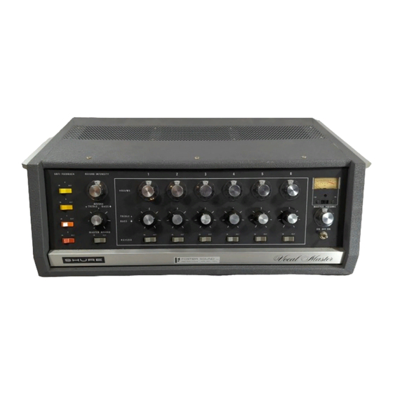
VA302 Series Vocal Master SPECIFICATIONS VA302 Series Console Amplifier Type ........All silicon transistor mixer/power amplifier . - Page 3 ..........W e i g h t . . 31.78 kg (70 Ib) including cable The Shure Model VA302 Vocal Master Sound System or short-circuit conditions of the amplifier outputs. The consists of one Control Console (VA302-C) and two output transistors are also protected against overheating Speaker Columns (VA300-S).
- Page 4 FIGURE 1. Individual Channel "Treble & Bass" Controls Front Panel Controls (Refer to Figure 1) (Six, Dual Concentric). 1. "Anti Feedback" Switches (Four). 7. Individual Channel "Reverb" Switches (Six). 2. "Reverb Intensity" Control. 8. "Master Volume" Control. 3. "Reverb Treble & Bass" Controls (Dual Concentric). 9.
- Page 5 7. Now turn up the other lndividual Channel Volume Con- General Operating Instructions: trols (5) which are being used. By use of the individual 1. Set all front panel controls in the following manner: All Channel Volume Controls (5), the microphones may be switches (I), (4), (7), set to "Out"...
- Page 6 Six individual input attenuator switches (24) are located The Shure VA300-S Speaker Column has been designed above the six input connectors. These screwdriver-slot to provide all of these features. It is recommended that...
- Page 7 If additional speakers (more than in the table above) are solid platform or box. required, use a Shure Power Master Amplifier to drive the Keeping in mind that the speaker columns have a narrow extra speakers. See page 12 for instructions.
- Page 8 nect the brown conductor of the cable to the "live" terminal VA302 Power Requirements: of the connector, the blue conductor to the "neutral" ter- The ~ ~ 3 0 2 - 6 Vocal Master is furnished with a three con- minal, and the green-yellow conductor to the "earth"...
- Page 9 If feedback occurs, locate the one Anti Feedback switch sentially the same way the individual channel tone controls (1) which eliminates the feedback. Gain may then be in- modify the non-reverb, or "dry" tones. The reverb tone con- trols allow the user to change the reverberant sound to creased or tone control increased until another feedback compensate for the reverberation of each room in which pitch is apparent.
- Page 10 Output" is provided for connections to tape recorders for "ground." See figure 4. making recordings, or to additional power amplifiers, such as the Shure Power Master PM300 Series. For specific in- structions for such connections, see the section marked Special Operating Instructions.
- Page 11 If additional microphone inputs are required, a micro- See the section on Microphone Level Output for wiring phone mixer (such as a Shure M68 type) or a second Vocal instructions. Master Console may be used. To use the "Auxiliary Hi-Level Output" on the Console,...
- Page 12 If it is necessary to use two Consoles on a permanent basis a factory authorized COMMON MIX. BUS MODIFI- CATION is available. Contact your Shure Dealer or the Shure Factory for further information on this. Additional Power or Area Coverage:...
- Page 13 Set the controls on the second Console as follows: Anti shielded type (such as Belden #8401, #8410, #8411) to avoid high frequency signal loss and to reduce the possi- Feedback'Switches to "Out," Master Reverb Switch "Out," bility of hum pickup in the cables. Individual Volume Controls to "0,"...
- Page 14 OUTPUT (HIGH/ L O W VA302-C SERIES FUNCTIONAL DIAGRAM FIGURE 11. VA302 Series Vocal Master from the back to permit access to the front panel. (Note: Amplifier Service (See Guarantee): Uncoil the cable before pushing the chassis. Push against The Vocal Master Console uses...
- Page 15 Q33 is an NPN have the same gain code as the original transistors. Shure transistor, while Q34 is PNP transistor. Refer to the lower...
- Page 16 FIGURE 13. FIGURE 14. Small Signal and Predriver Transistors: Check Transistors and Diodes: Transistors Q1 through Q30, Figure 14, Page 16, and Q31 Defective transistors and diodes may be located by use and (232, Figure 12, Page 15, are mechanically supported of an ohmmeter.
- Page 17 PM300E6 Power Master Booster Amplifier it prepaid to the factory. If outside the United States, return the A3PC Soft Cover Set unit to your authorized Shure Service Center for repair. The unit A3PC-C Console Soft Cover will be returned to you prepaid.
- Page 18 VA300-S Speaker Servicing: 1. Unplug cables from speaker jacks. 2. Using an ohmmeter, measure the resistance of the speaker column. The resistance should be between 12 and 16 ohms. Readings outside of these limits indicate possible failure. 3. Remove back of cabinet. 4.
- Page 19 The Commercial Alternates shown above are not necessarily equivalents but may be used in the event that direct factory replacements are not immediately NOTE: available. To maintain the highest possible performance and reliability, Shure Factory Replacement Parts should be used. 'When ordering 86A332 or 868332, specify current gain code. See Page 15.
- Page 20 6. To test transistors and diodes, see page 16. ages are: emitter 4.0, base 0.0, and collector 22.0. Shure part numbers are not shown in the parts list ac- companying the circuit diagram if parts are readily avail- A.C. Voltage Measurements: able through local electronic parts supply distributors.
- Page 21 VA302-C CIRCUIT DIAGRAM FIGURE 17.
-
Page 22: Supply Wiring
Eil(- VA302E-C POWER SUPPLY CIRCUIT DIAGRAM 120 VOLT POWER SUPPLY WIRING THERMAL OVERLOAD GRWBLK. BLACK T I BLUE 600 RED/BLK. 2 4 0 VOLT POWER SUPPLY WIRING YEL./BLK. GRN./BLK. FIGURE 18. VA302E6-C POWER SUPPLY CIRCUIT DIAGRAM 2 0 0 - 2 4 0 VOLT 1 . 6 AT 100- 140 VOL 2 4 0 V.