Table of Contents
Advertisement
Advertisement
Table of Contents

Related Manuals for AOpen GP1 Series


Summary of Contents for AOpen GP1 Series
- Page 1 Series Operation Manual...
- Page 3 For at mindske forurening og sikre beskyttelse af miljøet bedes De genbruge produktet. For yderligere infor- mation vedrørende indsamling og genbrug af elektronik-affald (Waste Elec- trical and Electronic Equipment (WEEE)) er De velkommen til at besøge vores website www.aopen.com og læse nærmere under “Green Products”.
- Page 4 Pour plus d’informations sur la ges- tion des déchets d’Equipements Electriques et Electroniques (DEEE ou WEEE), vous êtes invité à visiter notre site à www.aopen.com sous “ Green Products”. Entsorgungsanleitung (German) Zum besseren Schutze unseres Planeten, schmeissen Sie elektrische Geräte bitte nicht in öffentliche Mülleimer.
- Page 5 Para más información acerca de dónde depositar y cómo reciclar Equipos Electrónicos y Desperdicios Electrónicos (WEEE), por favor, visite la página web www.aopen.com y entre en la sección Productos Ecológicos (“Green Products”). Kassering (Swedish) För att bättre värna om vår jord bör denna elektroniska utrustning ej...
- Page 6 Copyright Copyright of this publication belongs to AOpen Inc. AOpen reserves the right to change the content of this publication without obligation to notify any party of such changes or revisions. No part of this publication may be reproduced, transcribed,...
-
Page 7: Safety Instructions
Safety Instructions 1. Please read these safety instructions carefully. 2. Please keep this User’s Manual for later reference. 3. Please disconnect this equipment from connecter before cleaning. Don’t use liquid or prayed detergent for cleaning. Use moisture sheet or cloth for cleaning. -
Page 8: Fcc Notice
FCC notice This device has been tested and found to comply with the limits for a Class B digital device pursuant to Part 15 of the FCC Rules. These limits are designed to provide rea- sonable protection against harmful interference in a residential installation. This device generates, uses, and can radiate radio frequency energy and, if not installed and used in accordance with the instructions, may cause harmful interference to radio communica- tions. - Page 9 CAUTION AND MAINTENANCE: Early malfunctions can be prevented. Careful and regular cleaning can extend the amount of time . Caution: Be sure to turn the power off and unplug the power cord before you begin any cleaning. CHECK THE FOLLOWING WHEN POSITIONING THE DISPLAY: •...
-
Page 11: Table Of Contents
Table of Contents I. GettingStart Thank-you Note Before You Get Started ............... 12 What’s In The Box?....................13 Accessories List ..................... 14 Optional Expansion Items ................ Panel and I/O Connector ..................Mainboard Overview (mini-ATX) ................CPU Frequency Table .................... 1.8 Install Memory/ Add-on module ............... II. - Page 12 We regret not informing about any changes in usage standards and other related information. AOpen Company reserves the right of altering or modifying the content of this manual. In case of any mistakes or incorrect descriptions, which include those on the products, AOpen makes no guarantee or commitments.
-
Page 13: Gettingstart
I. Getting Start... -
Page 14: Thank-You Note Before You Get Started
1.1 Thank-you Note Before You Get Started First of all, we would like to express our gratitude for purchasing our AOpen specially-designed GP1. Once again, this display-system is designed uniquely to meet all your personal needs with our great industry-designing ability and our everlasting perseverance to the quality of all our products. -
Page 15: What's In The Box
1.2 What’s In The Box? Open the GP1 box, you will find components as follow: ► GP1 chassis / Drives Cage ► GP1 "Easy Installation Guide" ► Accessory (In the accessory box) System Accessory Box Note: The pictures may look slightly different from the product you purchased, due to our constant product improvement effort. -
Page 16: Accessories List
1.3 Accessories List Bonus Disc 90W DC 19V Power Adapter (Device Driver Included) Power Cord(by Territory) Screw of HDD (4pcs) Screw of SATA ODD(4pcs) -
Page 17: Optional Expansion Items
1.4 Optional Expansion Items TV Tuner Kit (DVB-T) Wireless Kit TV Tuner Kit (ATSC) Wireless Antenna 802.11 b/g Wireless Antenna 802.11 b/g/n... -
Page 18: Panel And I/O Connector
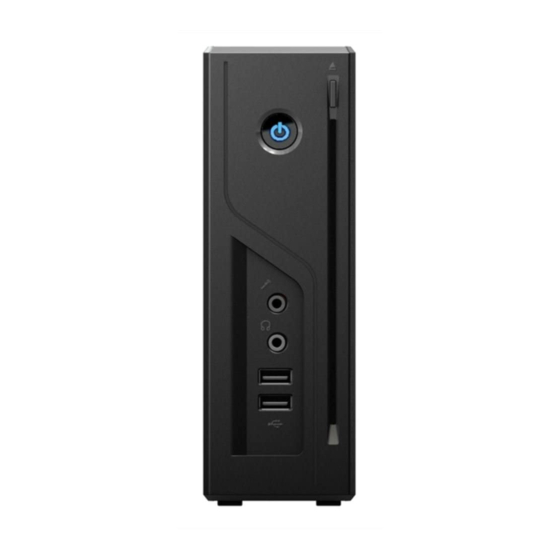
Panel and I/O Connector Kensington Lock hole Line in DVD Eject Button Line Out S/PDIF Out Power Button Wireless 802.11 Antenna hole Power eSATA Port Slot In Optical USB2.0 Port Device Drive USB 2.0 Ports (USB 3.0 Port for GP1-Plus) RJ45 LAN Jack Displayport Port Microphone... -
Page 19: Mainboard Overview (Mini-Atx)
1.6 Mainboard Overview Riser Card Slot Intel H61 Chipset (Intel H77 for GP1-Plus) LPC Debug Port Fan Power Port BIOS CPU LGA1155 Socket Front USB Port Front Audio Port Power Switch Port miniCard Slot x 2 DDR3 SODIMM Slot x 2... -
Page 20: Cpu Frequency Table
1.7 CPU Frequency Table Name Spec GP1 CPU Intel® Core™ i5-2390T Processor (3M Cache, 2.70 GHz) 35W GP1 CPU Intel® Core™ i3-2120T Processor (3M Cache, 2.60 GHz) 35W GP1 CPU Intel® Core™ i3-2100T Processor (3M Cache, 2.50 GHz) 35W GP1 CPU Intel®... -
Page 21: Install Memory/ Add-On Module
1.8 Install Memory/ Add-on module 1. Please make sure power plug had been removed. 2. There're tabs which located in the side of SODIMM holder. Detach the existing memory from the memory slot. 3. Put the memory module with correct direction. Notice there's one key position to make sure direction is correct. - Page 22 SODIMM slots are designed in the other side of MB which you could find it after remove the side cover and memory door by unscrewing two screws. Please insert the module straight down to the SODIMM slot with fingers and press down firmly until the SODIMM module is securely in place.
-
Page 23: Turn On The Power
II. Turn On The Power... -
Page 24: Bios Setting
2.1 BIOS Setting BIOS Setup when Screen After finishing the system assembly, power on and enter the BIOS Setup screen, then press <DEL> key during POST (Power On Self Test). Choose "Load Optimized Defaults" for recommended optimal performance. (Default setting is “SATA mode”) -
Page 25: Install Driver
2.2 Install Driver You can use the autorun menu of Bonus CD disc. Choose the utility and driver from the icons at left side, and then click on the “GO” button to complete installation automatically. Install Driver Install Utility Browse CD Contents Readme Exit CD... -
Page 26: Troubleshooting
Troubleshooting After connecting the peripherals to the system unit, the keyboard, mouse, and speakers does not work. The display monitor shows nothing. What should I do? You can check if you follow the correct installation procedure to make the connection. Check if the peripherals are connected to their respective connectors correctly. - Page 27 I have followed the installation processes mentioned in this manual, the system still does not work. Consult your dealer or authorized maintenance service personnel. Do not try to fix the system by yourself for it may cause unexpected damages to your system.
-
Page 28: Technical Support
Thanks for choosing AOpen products. We invite you to register at http://www.aopen.com to become a Gold Member of Club AOpen so as to ensure quality service in the future. In order to maintain the best service to every customer of us, we recommend you to follow the procedures below and seek help from our branches according to the region you buy the product. - Page 29 Online Manual: To download manual, please log on and then select your preferred language. Under “Type” directory, choose “Manuals” to go to our manual database. You can also find the manual and EIG in AOpen Bonus Pack. http://global.aopen.com/download.aspx Test Report: We recommend you to choose board/card/device from the compatibility test reports for assembling your PC.
-
Page 30: Rear Panel Connections
2.3 Rear Panel Connections Kensington Lock Hole Line in Line out Internet S/PDIF out DSL (Cable) Modem Power eSATA Port USB 2.0 Port Wireless 802.11 Antenna hole USB 2.0 Port USB 3.0 Port for GP1 Plus Expander (USB HUB) Card reader/Flash memory Web camera Joystick Projector... -
Page 31: Risk Of Overheating
Risk of overheating! Do not install device in a closed space. Be sure the ventilation holes in the device side for at least 2 inches or 5 cm of space for ventilation. To ensure that other objects do not cover the ventilation holes on device. With Fan Fanless... -
Page 32: The Instructions Of The Odd Eject Button
Please press the right mouse button / Eject (eject) on my computer / CD-ROM / function to eject the disk inside the ODD. Then replaced with the AOpen Driver disk/Bonus Disk and install "EZ Eject" software, and restart the system for activating the ODD eject button...