Table of Contents
Advertisement
PX865PE/ PX865P Series
Copyright
All rights are reserved. No part of this publication may be reproduced, transmitted, transcribed,
stored in a retrieval system or translated into any language or computer language, in any form or by
any means, electronic, mechanical, magnetic, optical, chemical, manual or otherwise, without the
prior written permission of the company. Brands and product names are trademarks or registered
trademarks of their respective companies.
The vendor makes no representations or warranties with respect to the contents herein and especially
disclaim any implied warranties of merchantability or fitness for any purpose. Further the vendor
reserves the right to revise this publication and to make changes to the contents herein without
obligation to notify any party beforehand. Duplication of this publication, in part or in whole, is not
allowed without first obtaining the vendor's approval in writing.
Disclaimer
We make no warranty of any kind with regard to the content of this user's manual. The content is
subject to change without notice and we will not be responsible for any mistakes found in this user's
manual. All the brand and product names are trademarks of their respective companies.
FCC Compliance Statement
This equipment has been tested and found to comply with the limits of a Class B digital device,
pursuant to Part 15 of the FCC Rules. These limits are designed to provide reasonable protection
against harmful interference in a residential installation. This equipment generates, uses and can
radiate radio frequency energy and, if not installed and used in accordance with the instructions, may
cause harmful interference to radio communications. Operation of this equipment in a residential area
is likely to cause harmful interference in which case the user will be required to correct the
interference at his own expense. However, there is no guarantee that interference will not occur in a
particular installation.
120410036M2N
Advertisement
Table of Contents

Related Manuals for Albatron PX865PE Series


Summary of Contents for Albatron PX865PE Series
-
Page 1: Fcc Compliance Statement
PX865PE/ PX865P Series Copyright All rights are reserved. No part of this publication may be reproduced, transmitted, transcribed, stored in a retrieval system or translated into any language or computer language, in any form or by any means, electronic, mechanical, magnetic, optical, chemical, manual or otherwise, without the prior written permission of the company. - Page 2 Addendum of PX865PE Series V2.0 In the PX865PE Series V2.0, we upgraded the AC’97 Audio Codec from ALC650 to ALC655 and the LAN Controller from 3C910 to 3C920. If you want to update the BIOS to V2.0, please refer to version R1.17 or later. For AC’97 controller driver updates please refer to the version 3.49 or later.
-
Page 3: Package Contents
PX865PE/ PX865P Series ® Intel 82865PE/ 82865P & ICH5 ® ® Supports Socket 478 Intel Pentium 4 Processor Enabling Hyper-Threading for your computer system requires ALL of the following components CPU: An Intel ® Pentium ® 4 Processor with HT Technology Chipset: An Intel ®... -
Page 4: Table Of Contents
Contents CHAPTER 1. GETTING STARTED ............1 ......................1 NTRODUCTION ......................2 PECIFICATION ................... 6 UICK ONTENT ABLE ....................... 7 ONFIGURATION Layout of PX865PE PRO ..................7 Layout of PX865PE....................8 Layout of PX865P PRO..................9 Layout of PX865P ....................10 .................. -
Page 5: Chapter 1. Getting Started
4GB. You can install unbuffered & non-ECC DDR400/ 333/ 266 (PC3200/ 2700/ 2100) DIMMs to PX865PE series. And you can install unbuffered & non-ECC DDR333/ 266 (PC2700/ 2100) DIMMs to PX865P series. These all support dual channel date Bus for the DIMM slots. -
Page 6: Specification
4 processor (Northwood/ Prescott) Supports Hyper Threading Technology Speed: 400/ 533/ 800 MHz Front Side Bus frequency (For PX865PE series) 400/ 533 MHz Front Side Bus frequency (For PX865P series) 33MHz, 32 bit PCI interface (PCI 2.3 compliant) 66MHz AGP 3.0 compliant interface that supports 8X/4X data transfer modes (0.8V or 1.5V) -
Page 7: Flash Memory
PX865PE/ PX865P Series Shadow RAM: These mainboard equipped with a memory controller providing shadow RAM and support for ROM BIOS BUS Slots: AGP slot (AGP3.0, 0.8/ 1.5V) x 1 32-bit PCI bus slot x 5 Flash Memory: Supports flash memory functionality Supports ESCD functionality Hardware Monitor Function: Monitors all fan Speeds... -
Page 8: Universal Serial Bus
PX865PE/ PX865P Series Universal Serial Bus: Supports up to eight USB ports for USB interface devices Supports USB 2.0 Enhanced Host Controller Interface (EHCI) and dual USB 1.1 Open Host Controller Interface (OHC1) I/O facilities: One multi-mode Parallel Port capable of supporting the following specifications: 1. -
Page 9: Watch Dog Timer
PX865PE/ PX865P Series AGP protection: This mainboard provides an AGP slot for 0.8V/ 1.5V AGP cards. The AGP protection function is to protect the mainboard and AGP cards if a 3.3V card is installed. Watch Dog Timer: This mainboard contains a special feature called the “Watch Dog Timer” which is used to detect when the system is unable to handle over-clocking configurations during the POST stage. -
Page 10: Quick Content Table
PX865PE/ PX865P Series Quick Content Table Function Content Location Page CPU Socket 478 DDR DIMM Slots DDR DIMM 1、2、3、4 ATX_12V、ATX_ PWR ATX Power Connector IDE1/2、SATA1/2 IDE Connectors FDC Connector AGP Slot PCI Slots PCI 1、2、3、4、5 CPU FAN、Chassis FAN、 CPUFAN、CHASFAN、AUXFAN Auxiliary FAN SW/LED、PWRLED Front Panel Indicator Speaker Connector... -
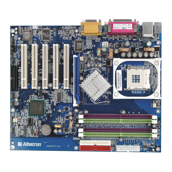
Page 11: Configuration
PX865PE/ PX865P Series Configuration Layout of PX865PE PRO KB/MS CPUFAN USB/LAN Socket 478 ATX_PWR PRT/COM ATX_12V SOUND Intel 82865PE AUXFAN Winbond W83627HF IDE2 IDE1 PCI1 PCI2 PCI3 3COM BAT1 PCI4 Intel USB4 CASE OPEN ICH5 SATA2 PCI5 SATA1 CHASFAN USB2 USB3 PWRLED CD-IN SPDIF... -
Page 12: Layout Of Px865Pe
PX865PE/ PX865P Series Layout of PX865PE KB/MS CPUFAN Socket 478 ATX_PWR PRT/COM ATX_12V SOUND Intel 82865PE AUXFAN Winbond W83627HF IDE2 IDE1 PCI1 PCI2 PCI3 BAT1 PCI4 Intel USB4 CASE OPEN ICH5 SATA2 PCI5 SATA1 CHASFAN USB2 USB3 PWRLED CD-IN SPDIF SW/LED FRONT AUDIO IrDA... -
Page 13: Layout Of Px865P Pro
PX865PE/ PX865P Series Layout of PX865P PRO KB/MS CPUFAN USB/LAN Socket 478 ATX_PWR PRT/COM ATX_12V SOUND Intel 82865P AUXFAN Winbond W83627HF IDE2 IDE1 PCI1 PCI2 PCI3 3COM BAT1 PCI4 Intel USB4 CASE OPEN ICH5 SATA2 PCI5 SATA1 CHASFAN USB2 USB3 PWRLED CD-IN SPDIF... -
Page 14: Layout Of Px865P
PX865PE/ PX865P Series Layout of PX865P KB/MS CPUFAN Socket 478 ATX_PWR PRT/COM ATX_12V SOUND Intel 82865P AUXFAN Winbond W83627HF IDE2 IDE1 PCI1 PCI2 PCI3 BAT1 PCI4 Intel USB4 CASE OPEN ICH5 SATA2 PCI5 SATA1 CHASFAN USB2 USB3 PWRLED CD-IN SPDIF SW/LED FRONT AUDIO IrDA... -
Page 15: Hardware Installation
PX865PE/ PX865P Series Hardware Installation This section will assist you in quickly installing your system hardware. Wear a wrist ground strap before handling components. Electrostatic discharge may damage your system components. CPU Processor Installation ® ® This mainboard supports Intel Pentium 4 processors using a Socket 478. -
Page 16: Memory Installation
CPUs that have clock speeds of 100 MHz. It supports DDR266/333 when installed with CPUs that have clock speeds of 133 MHz. And the PX865PE series supports also DDR266/320/400 when installed with CPUs that have CPU clock speeds of 200 MHz. -
Page 17: Ram Module Installation
PX865PE/ PX865P Series To Enable Dual-Channel DDR, the following conditions must be met: 1.You must use either DIMM1 & DIMM3 together or DIMM2 & DIMM4 together or all four DIMM slots together. 2.You must use matching DIMM configurations between DIMM1 & DIMM3. You must use matching DIMM configurations between DIMM2 &... -
Page 18: Back Panel Configuration
PX865PE/ PX865P Series Back Panel Configuration (optional) PS/2 Game Port Printer Port Mouse COM1 COM2 PS/2 Speaker Mic In Keyboard Line In PS/2 Mouse & PS/2 Keyboard Connectors: KB/MS The series mainboard provides a standard PS/2 mouse connector and PS/2 Keyboard connector. The pin assignments are described below: PS/2 Mouse Assignment... -
Page 19: Audio Port Connectors
PX865PE/ PX865P Series Serial and Parallel Interface Ports The series mainboard comes equipped with two serial ports and one parallel port on the back panel. These interface ports will be explained below. Printer Port COM1 COM2 Parallel Interface Port: PRT The parallel port on your system has a 25-pin, DB25 connector and is used to interface with parallel printers and other devices using a parallel interface. -
Page 20: Front Panel Indicator: Sw/Led、Pwrled
PX865PE/ PX865P Series Front Panel Indicator: SW/LED、PWRLED BIOS PWRLED DIM M1 DIM M2 DIM M3 DIM M4 SW/LED Pin Assignment Function Pin Assignment Function HD LED (+) Hard Drive Power LED (+) POWER HD LED (-) Power LED (-) Reset Control (-) Reset Power Button(+) Power-on... -
Page 21: Connectors
PX865PE/ PX865P Series Connectors Floppy Disk Connector: FDC The series mainboard provides a standard floppy disk connector (FDC) that supports 360K, 720K, 1.2M, 1.44M and 2.88M floppy diskettes. This connector supports the floppy drive ribbon cables provided in the packaging. Hard Disk Connectors: IDE1-2/ SATA1-2 The series mainboard has a 32-bit Enhanced PCI IDE Controller that supports PIO Mode 0~4, Bus Master, Ultra ATA 66/ 100. -
Page 22: Headers & Jumpers
PX865PE/ PX865P Series Headers & Jumpers Front USB Headers: USB2/ USB3/ USB4 You can connect the USB 4-Port Bracket to two of the USB2/ USB3 or USB4 header. There are four USB ports on the USB 4-Port Bracket which means you can connect four USB devices to one bracket. The mainboard supports up to eight USB devices including two on the back panel. -
Page 23: Case Open
PX865PE/ PX865P Series IrDA (Infrared Header) This IrDA connector can be configured to support wireless infrared and is used to attach to an infrared sensing device. After the IrDA interface is configured, you can use this connector for connectionless data transfer to and from portable devices such as laptops and PDAs. BIOS Ground IR_TX... - Page 24 PX865PE/ PX865P Series Clear CMOS Jumper: JP1 The “Clear CMOS” jumper is used when you cannot boot your system due to some CMOS configuration problem such as a forgotten password. This jumper allows you to reset the CMOS configurations, and then reconfigure. BIOS Pin1-2 short Normal (default)
-
Page 25: Audio Connectors
PX865PE/ PX865P Series Audio Connectors This mainboard provides three connectors as part of its audio Subsystem. Ground MIC_VREF Front out_R Rear out_R Front out_L Rear out_L FRONT AUDIO Left In BIOS Ground Ground Right In CD-IN SPD_OUT Ground DIM M1 DIM M2 SPD_IN DIM M3... -
Page 26: Slots
PX865PE/ PX865P Series Slots The slots in this mainboard are designed for expansion cards used to complement and enhance the functionality of the mainboard. PCI Slots AGP Slot BIOS DIM M1 DIM M2 DIM M3 DIM M4 AGP Slot This mainboard is equipped with an Accelerated Graphics Port (AGP) that supports 0.8V/1.5V AGP cards only. -
Page 27: Power Supply Attachments
PX865PE/ PX865P Series Power Supply Attachments ATX Power Connector: ATX_12V & ATX_PWR This mainboard requires two ATX power connections; a 20-pin connector and a 4-pin connector. Your power supply must have both connectors. Attach the 4-pin connector first, then attach the 20-pin connector. -
Page 28: Chapter 2. Bios Setup
PX865PE/ PX865P Series Chapter 2. BIOS Setup Introduction This section describes PHOENIX-AWARD™ BIOS Setup program which resides in the BIOS firmware. The Setup program allows users to modify the basic system configuration. The configuration information is then saved to CMOS RAM where the data is sustained by battery after power-down. -
Page 29: Key Function
PX865PE/ PX865P Series DRAM Support DDR (Double Data Rate) SDRAM (Synchronous DRAM) is supported. Supported CPUs ® ® This PHOENIX-AWARD™ BIOS supports the Intel Pentium 4 CPUs. Key Function In general, you can use the arrow keys to highlight items, press <Enter> to select, use the <PgUp> and <PgDn>... -
Page 30: Main Menu
PX865PE/ PX865P Series Main Menu When you enter the PHOENIX-AWARD™ BIOS Utility, the Main Menu will appear on the screen. The Main menu allows you to select from several configuration options. Use the left/right arrow keys to select a particular configuration screen from the top menu bar or use the down arrow key to access and configure the information below. - Page 31 PX865PE/ PX865P Series Main Menu Setup Configuration Options Item Options Description Set the system date. Note that the ‘Day’ automatically Date mm dd yyyy changes when you set the date. Time Hh: mm: ss Set the current time of the system. IDE Primary Options contained in Press <Enter>...
-
Page 32: Advanced Bios Features
PX865PE/ PX865P Series Advanced BIOS Features Hard Disk Boot Priority Select hard disk boot priority. First /Second/Third/ Boot Device Select the order in which devices will be searched in order to find a boot device. Options: Floppy、LS120、CDROM、ZIP100、USB-FDD、USB-ZIP、USB-CDROM、USB-HDD、 LAN、Disabled Boot Other Device The setting allows the system to try to boot from other devices if the system fails to boot from the 1st/ 2nd/ 3rd boot devices. -
Page 33: Quick Power On Self Test
PX865PE/ PX865P Series CPU L1 & L2 Cache Make CPU internal cache active or inactive. System performance may degrade if you disable this item. Options: Enabled (default)、Disable. Hyper-Threading Technology When you install a CPU include Hyper-Threading Technolong. And this item will allow you to enable or disabled the Hyper-Threading technology. -
Page 34: Advanced Chipset Features
PX865PE/ PX865P Series OS Select For DRAM > 64MB Select “OS2” only if you are running the OS/2 operating system with greater than 64MB of RAM. Options: Non-OS2 (default)、OS2 HDD S.M.A.R.T. Capability Self Monitoring Analysis and Reporting Technology is a technology that enables a PC to attempt to predict the possible failure of storage drives. -
Page 35: System Bios Cacheable
PX865PE/ PX865P Series DRAM RAS# Precharge This item allows you to select the DRAM RAS# precharge time. The ROW address strobe must precharge again before DRAM is refreshed. An inadequate configuration may result in incomplete data. This field is adjustable only when “DRAM Timing Selectable” is set to “manual”. This field is locked when “DRAM Timing Selectable”... -
Page 36: Resources Controlled By
PX865PE/ PX865P Series Resources Controlled By BIOS can automatically configure all the boot and Plug and Play compatible devices. If you choose Auto, you will not be able to manually assign IRQ DMA and memory base address fields, since BIOS automatically assigns them. Options: Auto (ESCD) (default)、Manual IRQ Resources When resources are controlled manually, you can assign each system interrupt a type, depending on the type of device using the interrupt. -
Page 37: Spread Spectrum
Factory Default Available Options CPU Host Frequency 2.66X Default (default), 2.00X, 2.50X, 【2.66X (Turbo) only for PX865PE series】 Default (default), 1.33X, 1.60X, 2.00X, 2.50X (Turbo), 2.66X (Turbo) 【only for PX865PE series】 Spread Spectrum The Spread Spectrum function can reduce the EMI (Electromagnetic Interference) generated. Options: Enabled (default)、Disabled... - Page 38 PX865PE/ PX865P Series For example, if your factory default “CPU Host Frequency” was 100, and you reset the “CPU Host Frequency” to 133, your AGP, PCI and SRC frequencies will be as follows: AGP Frequency = 133 / 1.5 = 88.67 PCI Frequency = 133 / 3 = 44.33 SRC Frequency = 133 / 1...
-
Page 39: Integrated Peripherals
PX865PE/ PX865P Series Integrated Peripherals Init Display First With systems that have multiple video cards, this option determines whether the primary display uses a PCI slot or an AGP slot. Options: AGP (default)、PCI Slot OnChip IDE Device IDE HDD Block Mode Block mode is otherwise known as block transfer, multiple commands, or multiple sector read/write. -
Page 40: Onboard Device
PX865PE/ PX865P Series IDE Primary / Secondary /Master / Slave UDMA Ultra DMA 100 functionality can be implemented if it is supported by the IDE hard drives in your system. As well, your operating environment requires a DMA driver (Windows 95 OSR2 or a third party IDE bus master driver). -
Page 41: Power On Function
PX865PE/ PX865P Series Onboard LAN Device This item allows you to enable or disable the LAN Device. Options: Enabled (default)、Disabled Onboard I/O Chip Setup PWRON After PWR-Fail This field will determine whether your system will boot after restoring power after a power failure. If you select “On”, the system will boot whether or not the system was on before power failure. -
Page 42: Ir Transmission Delay
PX865PE/ PX865P Series RxD, TxD Active This item determines the RxD and TxD frequencies. This field only configurable if “UART Mode Select” is set to “ASKIR” or “IrDA”. Options: Hi / Lo (default)、Hi / Hi、Lo / Hi、Lo / Lo IR Transmission Delay This item allows you to enable/disable IR transmission delay. -
Page 43: Ecp Mode Use Dma
PX865PE/ PX865P Series ECP Mode Use DMA Select a DMA Channel for the parallel port when using the ECP mode. This field is only configurable if “Parallel Port Mode” is set to “ECP”. Options: 3 (default)、1 Game Port Address Game Port I/O Address. Options: 201 (default)、209、Disabled Midi Port Address Midi Port Base I/O Address. -
Page 44: Power Management
PX865PE/ PX865P Series Power Management The Power Management Setup Menu allows you to configure your system to utilize energy conservation features as well as power-up/ power-down options. ACPI Suspend Type The item allows you to select the suspend type using the ACPI operating system. Options: S1 (POS) (default) Power on Suspend S3 (STR) -
Page 45: Video Off Method
PX865PE/ PX865P Series 2. Max. Saving Maximum power management (only available for sl CPUs). Suspend Mode = 1 minute HDD Power Down = 1 minute 3. User Defined (default) Allows you to set each mode individually. When this option is enabled, each of the ranges are from 1 minute to 1 hour except for HDD Power Down, which ranges from 1 minute to 15 minute and includes a “disable”... -
Page 46: Hdd Power Down
PX865PE/ PX865P Series HDD Power Down When enabled, the hard disk drive will power down after a certain configurable period of system inactivity. All other devices remain active. Options: Disabled (default)、1 Min、2 Min、3 Min、4 Min、5 Min、6 Min、7 Min、8 Min、9 Min、 10 Min、11 Min、12 Min、13 Min、14 Min、15Min Soft-Off by PWRBTN In situations where the system enters a “hung”... -
Page 47: Hardware Monitor
PX865PE/ PX865P Series Time (hh: mm: ss) Alarm You can choose the hour, minute and second the system will boot up. This field is only configurable when “RTC Wake Up” is set to “Enabled”. Reload Global Timer Events When a system goes into suspend mode, certain devices must be inactive for a period of time. Conversely, if any of those devices have any activity, the system will awaken. -
Page 48: Load Defaults
PX865PE/ PX865P Series Load Defaults Load System Default Settings Load System Default Settings. Load System Turbo Settings Load System Turbo Settings. Load CMOS From BIOS Load defaults from flash ROM for systems without batteries. Save CMOS To BIOS Save defaults to flash ROM for systems without batteries. -
Page 49: Exit Menu
PX865PE/ PX865P Series Exit Menu Save & Exit Setup Save all configuration changes to CMOS (memory) and exit setup. A confirmation message will be displayed before proceeding. Exit Without Saving Abandon all changes made during the current session and exit setup. A confirmation message will be displayed before proceeding. -
Page 50: Chapter 3: Software Setup
PX865PE/ PX865P Series Chapter 3: Software Setup Software Installation Place the Driver CD into the CD-ROM drive and the Installation Utility will auto-run. You can also launch the Driver CD Installation Utility manually by executing the Intel.exe program located on the Driver CD. - Page 51 PX865PE/ PX865P Series 3. Back to the main screen, click the “tools” button, you can choose the software to install. 4. Back to the main screen, click the “Browse CD” and you can browse the files on the Driver CD. Note: You can click the “Exit”...
-
Page 52: Chapter 4: Troubleshooting
PX865PE/ PX865P Series Chapter 4: Troubleshooting Problem 1: No power to the system. Power light does not illuminate. Fan inside power supply does not turn on. Indicator lights on keyboard are not lit. Causes: 1. Power cable is unplugged. 2. Defective power cable. 3. - Page 53 PX865PE/ PX865P Series Problem 4: System only boots from the CD-ROM. The hard disk can be read and applications can be used but booting from the hard disk is impossible. Causes: Hard Disk boot sector has been corrupted. Solutions: Back up data and applications files. Reformat the hard drive. Re-install applications and data using backup disks.
- Page 54 PX865PE/ PX865P Series Problem 10: Keyboard failure. Causes: Keyboard is disconnected. Solutions: Reconnect keyboard. Replace keyboard if you continue to experience problems. Problem 11: No color on screen. Causes: 1. Faulty Monitor. 2. CMOS incorrectly set up. Solutions: 1. If possible, connect monitor to another system. If no color appears, replace monitor. 2.
-
Page 55: Appendix I: Over Clocking
PX865PE/ PX865P Series Appendix I: Over Clocking Important Before you attempt to overclock your system, we strongly recommend that you obtain a thorough understanding of all of the variables, procedures, and the potential risks associated with overclocking. Because we cannot control of all of the possible variables that exist (i.e. memory, AGP card, user configurations, cooling apparatus etc), we cannot assume responsibility from damage to any components of your system due to overclocking. -
Page 56: Cpu Clock Ratio
PX865PE/ PX865P Series How to configure your new frequencies. As mentioned you must enter the BIOS Setup Utility in order to begin configuring overclocking parameters. After you reboot your system, press the “Del” key when prompted to enter the BIOS Setup Utility. - Page 57 PX865PE/ PX865P Series AGP/PCI/SRC Speed Setting This item determines the AGP, PCI and SRC frequencies (speed settings). You can set these frequencies using the supplied BIOS options. One of the options available to you is “Auto, Auto, Auto”. Using the “Auto, Auto, Auto” option will instruct the system to automatically calculate these frequencies based on the factory default “CPU Host Frequency”...
- Page 58 PX865PE/ PX865P Series Testing Even though you have configured your overclocking options and have successfully booted to your operating system, it doesn’t mean that you have successfully overclocked your system. Testing is an equally important aspect of overclocking and you must stress your configurations thoroughly to ensure stability.
- Page 59 PX865PE/ PX865P Series Example: This example shows you how to overclock the CPU Internal Clock, DDR frequency and FSB frequency for an Intel based mainboard. Note that the options that are supplied with your version of the BIOS may vary slightly. The example is for reference only.
-
Page 60: Appendix Ii: 5.1 Channel Setup
PX865PE/ PX865P Series Appendix II: 5.1 Channel Setup 1. After into the system, click the audio icon from the Windows screen. 2. Click Speaker Configuration button, you can see the screen like the picture below. 3. You can choice 2, 4 or 6 channel by your speakers. 2 Channel 4 Channel 6 Channel...