Table of Contents
Advertisement
Quick Links
Title & Document Type:
Manual Part Number:
November 1966
Revision Date:
HP References in this Manual
This manual may contain references to HP or Hewlett-Packard. Please note that Hewlett-
Packard's former test and measurement, semiconductor products and chemical analysis
businesses are now part of Agilent Technologies. We have made no changes to this
manual copy. The HP XXXX referred to in this document is now the Agilent XXXX.
For example, model number HP8648A is now model number Agilent 8648A.
About this Manual
We've added this manual to the Agilent website in an effort to help you support your
product. This manual provides the best information we could find. It may be incomplete
or contain dated information, and the scan quality may not be ideal. If we find a better
copy in the future, we will add it to the Agilent website.
Support for Your Product
Agilent no longer sells or supports this product. You will find any other available
product information on the Agilent Test & Measurement website:
Search for the model number of this product, and the resulting product page will guide
you to any available information. Our service centers may be able to perform calibration
if no repair parts are needed, but no other support from Agilent is available.
Errata
4935A Operating & Service
Manual
04935-90029
www.tm.agilent.com
Advertisement
Table of Contents
Troubleshooting

Related Manuals for HP 4935A


Summary of Contents for HP 4935A
- Page 1 Agilent Technologies. We have made no changes to this manual copy. The HP XXXX referred to in this document is now the Agilent XXXX. For example, model number HP8648A is now model number Agilent 8648A.
- Page 2 Operating and Service Manual HP 4935A Transmission Impairment Measuring Set Serial Numbers This manual applies to instruments with serial numbers prefixed: :2846A Copyright Hewlett-Packard Co./Colorado Telecommunications Division 1987 5070 7050, Centennial Blvd., P.O. Box Colorado Springs, Colorado 80933 ALL RIGHTS RESERVED...
- Page 3 Warnirlgs/(:autions Model 4YXA [ W A R N I N G SAFETY GROUNDING If this instrument is to be energized via an autotransformer interruption protective (grounding) conductor for voltage reduction, make sure the common terminal is (inside outside instrument) disconnecting connected to the earthed pole of the power source.
- Page 4 Cautions and Notes used the mstruct~on manual, then shall the apparatus be marked in HP Automatic Test System Manuals. wth thlssymbol (IEC 348;16a). Warnings, cautions and notes. (All) Warmngs and caut!ons shall precede the text Termnal dewces fad from the ~ntertor by live voltages that...
-
Page 6: Table Of Contents
Model 4935A Table of Contents TABLE OF C:ONTENTS P a g e S e c t i o n T i t l e S e c t i o n T i t l e P a g e 3-48. -
Page 7: Table Of Contents
Table of Contents Model 4935A TABLE OF CONTENTS (cord) T i t l e P a g e S e c t i o n T i t l e S e c t i o n P a g e... -
Page 8: Table Of Contents
Table of Contents Model 4935A TABLE OF CONTENTS S e c t i o n T i t l e P a g e S e c t i o n T i t l e P a g e 8-259. -
Page 9: Table Of Contents
Page Title Page Section Section 5-1. Output Level and Transmit Monitor l-l. Model 4935A Transmission Impairment Measuring Set ..........1-O Loop Adjustments......... .5-4 5-2. Receiver Adjustments........5-5 l-2. Charge Acceptance at Various 5-3. Hold Circuit Adjustments......5-9 Tempcraturcs.. - Page 10 8-21. 20 H z Waveform ..........8-43 7-25. Receiver Board Schematic 8-22. Transmit Monitor Test Output ....8-44 8-23. 4935A Signal Flow Block Diagram....8-67 Diagram (Sheet 1 of 2) ........7-36 8-24. Al Front Panel Schematic Diagram.... 8-69 7-26.
-
Page 11: Table Of Contents
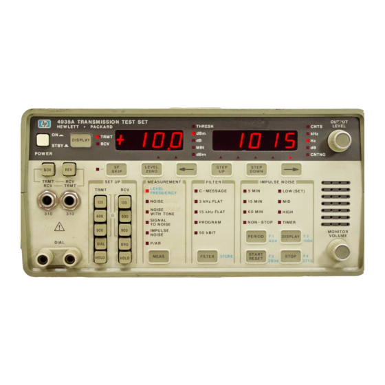
50 kBit Filter Test.......... .4-13 8-17. 4935A 50 kBit Filter........8-62 4-12. Notch Filter Test..........4-13 8-18. 4935A N o t c h Filter.........8-62 Impulse Noise DAC Test ......4-15 8-19. 4935A P/AR Filter ........8-62 4-13. - Page 13 (hctral Inii,rmi,ti~,,, Model 4935A Figure f-1. Model 4935A f ransnhdon Impairment Measuring set...
-
Page 14: Locator
This Operating and Service manual contains information to install, operate, maintain, and service the HI’ Model 49:{5A Transmission Impairment Measuring Set (TIMS). Figure 1-l shows the HP Model 49XA with cover and power cord. The manual is divided into eight major sections which provide the following information: SECTION I. - Page 15 Model 49:EA Table l-l. Specifications R E C E I V E R TRANSMITTER Frequency Frequency Frequency Range....20 Hz to 110 kHz Frequency Range ..20 Hz to 110 kHz Resolution Accuracy Resolution...
-
Page 16: Level A N D Frequency
General Information Model 4935A T a b l e l - l . SpecificatilJns (Continued) R E C E I V E R TRANSMITTER Noise with Tone Noise with Tone Filter..>50 dB rejection from 995 to 1025 H Notch Frequency . -
Page 17: User Repair
(;cnt~r:tl Inf’orm;rtIotl 1-9. SAFETY CONSIDERATIONS 1-12. RELATED MANUALS ( lI)t.ritting int’t~rtnation is summariztd on it t,arcl in the instrumt~nt t‘ovtsr. 1 1:; l-14. USER REPAIR I I .-I. 1 ntctrnal rthpairs tcl thta instrument should t)rl dents by ;tuthoriztd rtbpair shops only. I~orassistant~t~, c,ont;it.t thus tlta;lrtsst t It~u,l~~tt-~‘at,kartl Sales antI Servit,ta Of’fit~, listed at the r(‘ar of’... -
Page 18: Recommended Test Equipment
Model 4935A 1-2. Table Recommended Test Equipment MODEL INSTRUMENT CRITICAL SPECIFICATIONS RECOMMENDED USE* AC CALIBRATOR OUTPUT LEVEL 1 mV TO 1 OV FLUKE 5200A FREQUENCY: 20Hz TO 11 OkHz OR EQUIVALENT ACCURACY O.l%@>7mV HP 1740A OSCILLOSCOPE > 15MHz BANDWIDTH A VS B CAPABILITY... -
Page 19: L-29. Operating Temperature
The internal battery pack consists of three rechargeable battery packs (+6V, +156V, and -156V). These provide typically 2.5 hours of continuous use without recharging. To recharge the battery packs, connect the HP 4935A to an AC power source and press the power switch to STBY. Normal recharge time is about 17 hours. - Page 20 Refer to Section IV for electrical checks. 2-5. If the unit is mechanically damaged or fails electrical tests, notify the carrier and the nearest HP officbe (listed at the rear of this manual). Hewlett-Packard will arrange for repair or replacement of the instrument without waiting for claim settlement.
-
Page 21: Operating Environment
Hewlett-Packard sales and service offices listed at the rear of this manual. If the instrument. is returned to HP for repair, attach a tag listing the type of service or repair needed. Include return address, model number, option number (if applicable) and complete serial number. Also, mark the container ”... - Page 22 Installation Table 2-1. HP Plus Stvles F o r U s e I n C o u n t r y United Kingdom. Cyprus Nlgerla Australea New Zealand East and Wesl Europe, Saudi Arabta Egypt. Africa. lndla unpolarlred in many natIons Umted S t a r e s Canada.
- Page 24 Operation SECTION III OPERATION INTRODUCTION 3-1. :3-z. This section contains information on front and re jr panel features, self check procedures, and error c-odes ( Err-c,otlrs). Also covered are the principles of operation for all measurements. If any of the automatic self’...
- Page 25 Model 4935A Figure 3-1. Front and Rear Panel Controls/Connectors/Indicators...
- Page 26 Operation Model 49XiA CONTROLS, CONNECTORS AND INDIC.ATORS Power Cord Module. Accepts power cord supplied with instrument. Contains line fuse and PC board for selecting line voltage (see Section II, paragraph 2-9 for procedure to select line voltage). (WARNINGI Always connect power cord to a proper y grounded 3-wire power outlet. Do not connect more than 200VDC signal to terminals.
- Page 27 Model 4935A Operation 1TRCV Mode (left display) and IMPULSE NOISE; + or + selects the position of the threshold digit to be increased or decreased. Lighted cursor indicates one-of-two digit positions. Digit value is inc.remented by pressing STEP UP and decremented pressing STEP DOWN.
- Page 28 Operation Model 49:l:iA OUTPUT LEVEL Control from -40 dBm to +13 dBm. Output level is Adjusts the transmitter output level continuou;ly displayed on left display. MONITOR VOLUME Control and Speaker. Permits adjustable volume for listening to the cirl:uit under test or to the Test Set Transmitter. F i g u r e 3 - I .
-
Page 29: Measurements
2-9 of Installation section for procedure to select line voltages. Always connect power cord to a properly grounded 3-wire power outlet. Press POWER button ON. The 4935A will automatically do a self check of the transmitter, the filters, and the LEDs. - Page 30 Operation MEASUREMENTS 3-9. LEVEL FREQUENCY-TRANSMITTER Use MEAS key to select LEVEL FREQUENCY. Press I)ISPLAY-TKMT key to display the transmitted signal. TRMT light is ON. I,rvel can be read in the left display and frequency in the right. If SF signalling units are used on the circuit under test, press SF SKIP key to turn on SF SKIP.
- Page 31 Model 49315A Operation LEVEL FREQUENCY-RECEIVER Use MEAS key to select LEVEL FREQUENCY. Press I)ISPI,AY key to display the reckeived signal. The RCV light will come ON Read the RCV level in the left display. A sign indicates the received signal is :,+I 3 dRm. A -sign indicates received level is <...
- Page 32 Operation NOISE -TRANSMITTER Press DISPLAY TRMT-RCV key to display the transmitted signal. TRMT light will be on. Press MEAS key to select NOISE. There will be no values displayed because in this configuration the transmitter is turned off and a quiet termination is supplied to the TRMT jack.
- Page 33 Operation Model 4935A 4 9 3 5 A T R A N S M I S S I O N T E S T S E T n THRLSH H E W L E T T . PACK,aRD NOISE WITH TONE - TRANSMITTER Press MEAS key to select NOISE WITH TONE.
- Page 34 Operation SIGNAL TO NOISE - TRANSMITTER Press MEAS key to select SIGNAL TO NOISE. Press DISPLAY TRMT-RCV key to display the transmitted signal. TRMT light will be on. Turn OUTPUT LEVEL knob to adjust 1004 Hz signal to data level (usually 13 dB below the transmission level point).
- Page 35 Model 49):2X TEST 4935A TRANSMISSION Hl I WLETT . PACKARD [----I POWE I 4 IMPULSE NOISE - TRANSMITTER Press MEAS key to select IMPULSE NOISE. Press DISPLAY TRMT-RCV key to display the transmitted signal. TRMT light will be on. Press FILTER key to select the same filter as the receiver will use. Although the...
- Page 36 Operation OUTPUT 4935A TRANSMISSION TEST IMPULSE NOISE - RECEIVER Press MEAS key to select IMPULSE NOISE. Press DISPLAY TRMT-RCV key to display the received signal. RCV light will be on. Press FILTER key to select the appropriate filter. (‘. Use STEP UP, STEP DOWN and f- + keys to adjust the level of the LOW threshold shown in the left display.
- Page 37 Opwatiofr Model 4935A 4935A T R A N S M I S S I O N T E S T S E T NOISE TO GROUND - TRANSMITTER (STANDARD UNIT and Option 001) Press DISPLAY TRMT-RCV key to display the transmitted signal. TRMT light will be on.
- Page 38 Operation &I HEWLETT . PACKARD 4935A T R A N S M I S S I O N T E S T S E T OTHRESH DIAL P/AR - TRANSMITTER (Option 002 and 003) Press DISPLAY TRMT-RCV key to display the transmitted signal. TRMT light will be on.
- Page 39 Push the TRMT DIAL switch again to release it. This disengages the dial circuitry and allows testing. If the 4935A is designated the receive set, press RCV HOLD switch and then push REV switch to connect RCV side to left 310 jack.
-
Page 40: Input-Output Switching
Operation MEASUREMENT PRINCIPLES 3-10. :1-I I. ‘I’hc~ principlrs for making mcasuromcnts with the 4Y:GA are described in the following paragraphs. Includrd arc explanations of the measurcmcnts and the effects of certain parameters on data transmissicjn. 3-12. INPUT-OUTPUT SWITCHING :i-I :I. ‘I’ho TKMT and IICV 310 jacks provide connrction between thr 49335A and the circuit under test. -
Page 41: Level And Frequency Measurements
Operation M o d e l 493EA ‘I’hcb ,Il):IT,A input and output circuits are balanced to match standard voice channel lines. A :;-17. tlal:ltl(.tad lint, is t~l~~ctrically symmetrical; the two sides of’ the line have equal series resistance, series induc~tancx~, shunt capacitancca, a n d leakage-tc,-Krounti. -
Page 42: Sf Skip
The message circuit measurement is obtained by measuring the noise present on a line with a quiet :%-x4. termination on one end (supplied by the transmitting 49XA) and a weighted measuring device on the other end (receiving 4935A). :I-35. The C-message filter measures noise signals that annoy the typical telephone service subscriber. -
Page 43: Khz Flat Weighting Characteristic
Model 49‘EA <r * Operation ' 1 0 1000 2000 3000 5000 Figure 3-6. C-Message Weighting Characteristic 1000 3000 4000 6000 Frequency (Hz) Figure 3-7. 3 kHz Flat Weighting Characteristic... -
Page 44: Khz Flat Filter
Operation Model 49:15/I :!-:I7 ‘I’ho program weightrd filter is designed for wcbightd noise mcaasurcments on program channels US(YI primarily by thr hrondcast industry to c~ommunicate hetwrrn studio and transmitter site (SW IJigurr lb :xw. ‘l’ht~ 15 kHz flat f’ilttbr is also dcsigneti f’or measuremc~nts on program c~hannrls. I,ike the : 3 kHz flat filt.clr, 1 t inc~lutles low t’requrncy noise in the measurr~mc~nt (SW Figure :]-$I). -
Page 45: Noise-With-Tone
The received noise level is displayed in units of d&n. Figure :3-l illustrates the combination of the (:-message weighting and notch filter characteristics. The 4935A combines th(s notch with any of the five filters. 3-45. -
Page 46: C-Message Weighting With Notch Characteristic
Operation Model 4’135A - 1 0 - 2 0 - 3 0 - 4 0 - 5 0 1000 2000 3 0 0 0 5000 Figure 3-l 1. C-Message Weighting with Notch Characteristic 1004 Hz SIGNAL + NOISE ,‘, C O M P A R E ,004H2 TELEPHONECIRCUIT ‘SIGNAL... -
Page 47: Impulse Noise
Operation Model 49:EA 3-48 SINGLE FREQUENCY INTERFERENCE :1-31). Single frequency interference refers to unwanted steady tones which may appear in lines. ()cc;tsion;tl bursts of low level tones which may occur from crosstalk of multifrequency signalling, for t~xampl~~, do not fall in this category. Single frequency tones may interfere with certain data signals, particularly narrowband signals which are multiplexed onto a voiceband channel. -
Page 48: Noise-To-Ground Measurement
The 49XA uses noise-to-ground to measure the longitudinal noise present on a telephone circuit, :I-M. with reference to ground. The transmitting 4935A provides a quiet termination at one end of the voice channel. and the receiving 4935A provides a frequency weighted filter and detector at the other end. The basic measurement technique used for the noise-to-ground measurement is very similar to the message circuit noise measurement;... -
Page 49: P/Ar Transmit Signal Envelope
Model 4935A K E Y F R E Q U E N C Y 1 4 0 . 6 2 5 3 9 0 . 6 2 5 6 4 0 . 6 2 5 8 9 0 . 6 2 5 1 1 4 0 . - Page 50 Model 49’ISA Operation :i-6 1. The P/‘AR measurement is a single number rating of the fidelity of a voiceband channel and is a weighted measure of the total attenuation, phase distortion, and noise. The P/AR rating is derived by comparing the P/AR of an ideal signal with the P/AR of the output signal of the system under test. The P/AR measurement is most sensitive to envelope delay distortion and is also affected by noise, bandwidth reduction, gain ripples, nonlinearities such as compression and clipping, and other impairments.
-
Page 52: Performance Tests
Performance Tests Model 49:GA SECTION IV PERFORMANCE TESTS 4-l. INTRODUCTION 4-2. Tests in this section verify instrument specifications. These tests may be used as part of incoming inspection and can be done without accessing the instrument’s internal circuits. If the instrument fails the tests, refer to the Service Section. - Page 53 A(lj\lst 49:l:iA I,E:VEI, until 2.4:35 Vrms (9.95 d&n into 600 ohms) appears on the L’l~limetrr (notcx: 4935A must be terminated as shown above. (‘t1(a(,k the 49:GA transmitter at the frequencies listed in Table 4-I Ai, X,i kHz verify that the 49:ISA frequency when measured with the counter is between 84.996 kHz...
-
Page 54: Transmitter Flatness A T + 10 Dbm
Performance Tests Model 49:15A PERFORMANCE TESTS Table 4-l. Transmitter Flatness at +lO dBm ACCEPTABLE VOLTAGE RANGE FREQUENCY 2.17 to 2 73 V r m s 20 Hz 2 38 to 2 4 9 V r m s 200 Hz 2 38 to 2 4 9 V r m s 5 kHz 2.38 to 2 4 9 V r m s 15 kHz... -
Page 55: Transmitter Flatness A T -40Dbm
Model 49:GA PERFORMANCE TESTS Transmitter Flatness at -40 dBm 4-14. SE’I’I I I’: M O D E L 4 9 3 5 A VOLTMETER OOOQQ CALIBRATOR Figure 4-2. Transmitter Flatness Test at -40 dBm IJlukc 52OOA AC (:alibrator : 1 IO to banana adapter I 20 dH amplifier (set: figure 4-I ii) 2 banana plug test cables 111’... -
Page 56: Transmitter Flatness A T -40 Dbm
Substitute the 4935A TRMT output in place of the AC Calibrator. LJse the STEP UP or STEP I)( )WN buttons in conjunction with the - or - buttons to set the 4935A TRMT frequency to 20 Hz Ido not adjust the OUTPUT LEVEL). - Page 57 PERFORMANCE TESTS Table 4-2. Transmitter Flatness at -40 dBm (Cont’d) Vout fO.2 dB 2 0 0 H z -1~0.5 dB 5 0 H z & to.2 dB 1 5 kHz LO.5 dB 6 0 kHz ‘l.OdB20Hz i 0 . 5 dB 8 5 kHz (in mV) 8 4 2 t o 6 6 8 7 9 4 t o 7 0 8...
-
Page 58: Abbreviated Transmitter Flatness
Ihe 4935A l o Adjust the OUTPUT LEVEL until 0.775V(O dBm) appcors on the Voltmctcr. Cheek the 4935A transmitter at the frcqucncics given in Table 4-3. Table 4-3. Abbreviated Transmitter Flatness V O L T A G E S ( V R M S ) - Page 59 1 banana plug cable HN(: “1”’ (‘onnect the AC Calibrator to the 4935A RCV jack as shown in Figure 4-4. Setup the 4935A as follows: ....ON POWER .
- Page 60 AHHRE:VIATEl1 RECEIVER ACCURACY TEST the test setup shown in Figure 4-:3. LJse Stlt the AC Calibrator to .7791 V (-0.05 dBm into 600 ohms). Test the 4935A at each frequency given in Table 4-5. Table 4-5. Abbreviated Receiver Accuracy Test Table LEVEL FREQUENCY FREQUENCY ( 0 .
-
Page 61: Autorange Test
M O D E L 4 9 3 5 A Figure 4-4. Autorange Test I”luk(l 52OOA A(: Calibrator 1 banana plug test cable I BNC to bantina adapter (:onnect. equipment as shown in Figure 4-4. On 4935A select: POWER r)rsI'I~AY':::::::::::::::::::::::::::::::::::::::::::::::::::::::::'R(:V press RCV (iOOf2 SW IJP MEASI!KEMENT . -
Page 62: Filter Tests
FILTER . select according to test C-MESSAGE FILTER Select the C-MESSAGE filter on 4935A. Check the response at each frequency in Table 4-7. The 4935A should be within the range given Table 4-7. C-Message Filter Test FREQUENCY RECEIVED LEVEL (dBrn) -
Page 63: Khz Flat Filter Test
75-80 F’RO(;RAM I”II,‘l’ER TEST S&ct the PROGRAM filter on the 49XA. ( ‘hrck the response at each frequency in Table 4-l 0. The 4935A display should be within the range given. Table 4-10. Program Filter Test RECEIVED LEVEL (dBrn) FREQUENCY... -
Page 64: Notch Filter Test
35000 84-86 62-67 50000 NOTCH FILTER TEST Sclcct the I5 kHz Cltcr and NOISE WITH TONE mcasurcmcnt on the 4935A. Cheek the rcsponsc at each frcclucncy in Table 4-12. The 4935A should bc within the range given. Table 4-12. Notch Filter Test... -
Page 65: Impulse Noise Dac Test
I’ress IjlSPl,AY in IMPUI,SE NOISE to select MI11 threshold. Set the A(: (Ldibrator to 0.820 V; the 4!):<5A display should not count. 1 0 . Set the A(: Calibrator to 0.920 V; the 4935A display should count. I’ress 1)ISPLAY in IMPULSE: NOIEX to select HIGH threshold. I:{. - Page 66 Model 493A Performance Tests PERFORMANCE TESTS Table 4-13. Impulse Noise DAC Test AC CALIBRATOR PEAK SIGNAL COUNTING COUNTING VOLTAGE IN dBm THRESHOLD THRESHOLD 0 580 0 651 1 . 5 0 730 2 . 5 0 820 3 . 5 0 .
-
Page 67: Count Limit Test
‘1. Press the STAII’I’/KESF:T button. L% ai t , 60 seconds and press STOP. The 4935A right display should indicate 480 +48 counts. I’ress Impulse Noise I)ISPI,AY button to selrct MI11 threshold. ‘I’hch l!XEA display should indicate 480 lf-48 counts. -
Page 68: Termination Impedance Test
Figure 4-8. Termination Impedance Test EQIJII’MENT: HP 3490A Multimeter 1 310 to BNC adapter BNC to dual banana adaptor Resistors - 90011, 60012, 13511 Disconnnect 4935A from AC power. Connect equipment as shown in Figure 4-8. On 4935A select: POWER STBY ,.... - Page 69 I’erformancr ‘f’rsts Model 49XA PERFORMANCE TESTS fCq>t~at the f’olfowing test three times. ‘f’hc procrtfurr and the expected result remain the same. tc~rmination impcdancrs sclccted and the vnlur of thta resistor placed across the R(‘V jack will c,hangfl. F i r s t use a 9OOIl rrsistor, second a 6001!, and finally u I;Cll resistor.
-
Page 70: Hold Tone Dropout Detector Test
Set AC Calibrator to 1OmV at 1004 Hz. I,ower the AC Calibrator level until Err 7 appears on the 4935A (between 3-4 mVrms). On 4935A select LEVEL FREQUENCY and read the signal level from the display. It should be-46 dHm -t:! dRm. -
Page 71: Hold Circuit Test
N O R prcs\ SET UP - press in TRMT IHOLD prcm in RC’V HOLD T h e DC.’ currcn( on Lhc milliamniclcr 24.OmA +.SmA. sl~ould Ihc 4935A press in Ihc REV btt(ton. +SmA Rc\,crsc the power supply Icads. The DC currcn(... -
Page 72: Distortion Test
AUDIO ANALYZER Figure 4-l 1. Distortion Test EQIJIPMENT: HP 6234A Dual Output Power Supply HP 8903A Audio Analyzer 4 kHz Low Pass Filter (included in Diagnostic Service Kit)* 20 dB amplifier (included in Diagnostic Service Kit)* 2 310 to BNC adapter... -
Page 73: Dbm Distortion Test
Performance Tests Model 4935A PERFORMANCE TESTS Turn off the 30 kHz low pass filter on the Audio Analyzer. Measure distortion at the following points. . _ , I DISTORTION FREQUENCY OUTPUT LEVEL al + 9 dBrn 1 1 0 kHz... -
Page 74: Filter Circuits
IC OP Amp 3101-0973 DPDT Switch 3101-0973 DPDT Switch 1251-3677 310 Jack 151 O-0076 Binding Post 151 O-0076 Binding Post 151 O-0076 Binding Post 1251-1780 BNC Connector * The Diagnostic Service Kit (HP 04935-60014) contains a test board with this circuit. 4-23... -
Page 75: Abbreviated Distortion Test
Performance ‘Pests Model 4935A PERFORMANCE TESTS AHHf~P:VIATICT) l)ISTORTION TEST I jisconnect all cables from the 49XA input. ( h 49:KiA select: POWER . ON I)ISf’I,AY . SET111 press in both NOR and REV buttons MEASIJREMENT . SIGNAI, TO NOISE OIJTI’IJT LEVEL adjust to 0.0 dHm. -
Page 76: P/Ar Test
2300 - 1 0 dBm Press DISPLAY to change the 4935A to TRMT mode. The right display should read 100 +l. Vary the OUTPUT LEVEL to obtain a left display reading between -12 dBm and -1 dBm. The P/AR reading in the right display should not change by more than 1 P/AR unit. -
Page 77: Noise-To-Ground Test
AC‘ IHIGH. and cot~ncct to Lhc Short -1035~4 input (lip Calibralor Set AC Calibrator output to .7746 Vrms at loo0 Ilz. 4935A display should typically read ‘XkiBrn + 2dBrn. ‘I‘IICIX i\ no .\l)lw\ iatccl Grountl Noise to Test. -
Page 78: Autorange
Performance Tests Performance Test Record 4935A D A T E RESULTS FAIL DESCRIPTION PASS Self Check Transmrtter Flatness at +lO d B m Transmrtter Flatness at -40 d B m Recewer Accuracy at +12 d B m and ~40 d B m... -
Page 80: Procedure
For the complete procedure refer to the Mechanical Disassembly Procedure in Section VIII, Service Section. When the 4935A is in STRY, AC power is still present in the instrument as well as some DC voltages. Disconnect AC power from the instrument before opening the case or removing any assemblies. - Page 81 Ad,jus~mcrl(~( ‘alilmlion M o d e l 4935A 5-11. ADJUSTMENTS 5.12. Ad.iwtmcnts s h o u l d hc done i n lhc s c q u c n c c given. Power SuppI) xl iurlmcnts shoulcl bc done p r i o r t o m a k i n g a n y inlcrn:ll adjtlslmcnls.
- Page 82 ..........1)C Voltmeter HP 3490A Oscilloscope .
-
Page 83: Output Level & Transmit Monitor Loop Adjustments
M o d e l 4935A ADJUSTMENTS 5-14. Output Level and Transmit Monitor Loop Adjustments RFFERIINCE: Tran\mittcr Asscmbl) C’I’: M O D E L 4 9 3 5 A V O L T M E T E R Figure 5-1. Output Level and Transmit... -
Page 84: Receiver Adjustments
ADJUSTMENTS 5-l 5. RECEIVER ADJUSTMENTS REf’ERf!N(‘E: A3 Rcccivcr Assembly EQIJII’MENT: AC-DC vollnlckr - t1r 3455 AC‘ C‘aIibr;Itor - Fluke 52OOA on 4035A sclcc\: DISPLA1’ T R M T MEASUREMENT - NOISE NOR/fIEV - NOR Offset Ad iusltncnl: Short A3TI’I 0 to A3TP2 I Short A3T1’22 to A3TP23 Mcasurc the DC voltage... - Page 85 Motlcl 4935A ADJUSTMENTS M0i.c the ACVM to A 3 T P 2 5 and acl,iust A3R77(RCV GAIN) [or ;I reading of 8 I6mV +WmV. ,ZJiust AiR23 (AVG DET) until the display flickers bclwccn 0.3and 0.5 d B m . LEVEL FREQLIENCY...
-
Page 86: Notch Filter Adjustments
Model 45X1511 Adjustment/Calibration ADJUSTMENTS 5-17. Notch Filter Adjustments REP‘l’R~N(‘E: Receiver Assembly b:Q1JlI’MICN’1’: 1741A Oscilloscope I’RO( ‘El)1 JIG:: I~:xternally loop the TRMT jack to the RCV jack. On 19:GA select: IlISPI,AY . T R M T M E A S U R E M E N T IXVI31, F‘RICQUENCY Set thr displayed frequency on the right display to 995 Hz. - Page 87 ()n the Oscilloscope select A vs H operation and connect the probes to the normal input jack. fj’or HP model 180 series oscilloscopes, f’eed one input to channel A and the other to the external horizontal input - not the external trigger input.
-
Page 88: Hold Circuit Adjustments
3455.A Milliammctcr - I-IP 3466A I’OWCI. S u p p l y - HP 62 I HA C’onncct ccfuipmcnt ;I$ shown in Figure 5-3. Chcch the power suf~ply output \vith the DC Voltmctc~~. All,iust the outf~ut to h.9V +.2 VDC. -
Page 89: Replaceable Parts List
6-5. ORDERING INFORMATION To order a listed part, quote the HP Part Number, indicate the quantity needed and address the 6-6. order to the nearest Hewlett-Packard Office. When ordering a non-listed part include the instrument model number, serial number and a description and function of the part. Address the order to the nearest Hewlett-... - Page 90 Table 6-1. Reference Designations Abbreviations (I of 2) R E F E R E N C E D E S I G N A T I O N S jumper Integrated cIrcult, r e l a y non-repaIrable a s s e m b l y Inductor vacuum tube, meter...
- Page 91 Keplaceahlc Parts Table 6-1. Reference Designations and Abbreviations (2 of 2) ABBREVIATIONS I>IC” I1 0 R V T T R N turn ll”el pllltt’d ~‘irclllf R W V reverse working voltage T T L transistor-transistor logic pr,rltPd I:lrCUIt atsrmt,ly T Y P typlcal P C A ~,lcofJl‘rd...
- Page 92 I T E M DESCRIPTION HP PART NO. Q U A N T I T Y Case; top half ,&;a; Front Cover 5040-4469 Instruction Card 0493590018 Handle- Case 5040-4470 Cap- Handle 7120-5370 Screw; Machine 2520-0014 Foot, Bumper 5041-6750 Screw; Machine 2520-0014 Case;...
-
Page 93: Exploded View Assemblies And Cables
QUANTITY HP PART NO. ITEM DESCRIPTION Receiver Assy(Std) 04935-6000’S .,3 2. Receiver Assy(P/AR) 04935-6OOm -j 9 Coax Cable 0493560009 Shield; Metal Mounting 04935-00002 Cable 4 wire twisted 5060-7167 04935- JO?& &, Switch Board Assy Front Panel(Std) 04935 iiibhl Front Panel(P/AR) - Page 94 Model 4935A ITEM DESCRIPTION HP PART NO. QUANTITY Cable(Batt Opt Interconnect) 8120-3181 Standoff, Plastic 5040-4467 Cable, Recflran. Interconnect 8120-3126 Shouldered Fiber Washer 3050-l 021 Transistor Insulator 034450949 Nut,Hex No.4 Trans. MTG 0590-0663 Screw No. 4, MTG 2200-0521 Transistor Pwr (PO Item 17)
-
Page 95: Exploded View Battery Option
ITEM DESCRIPTION HP PART NO. QUANTITY Battery Assy 04935-62904 Screw 2510-0103 Washer 3050-0001 Screw 2360-0117 Battery Charger Board 04935430029 Receiver Assy(Std) 04935-60032 Receiver Assy(P/AR) 04935-60034 Screw 2360-0370 Shield; Metal MTG 04935-04701 Insulator 04935-45401 Label - ID 04935-800 14 Cable: P/O Battery... -
Page 96: Manufacturer Code List
Model 49:EA Table 6-2. Manufacturer Code List MFR NO. MANUFACTURER NAME ADDRESS ZIP CODE 1’ 1 1 ‘,I~M~I:IJNDIII;IOR t’llOD I)t I’1 I’YRIIt II n (.llHI’ A’iliLRNlr PI~clI)lil:l’, Cl I> [If XII RNI I Nr Il:ONlX :; I l;Nt / I r:S 1:1113P I’r:O/l I.El: IIfA CllRt HAliHl’i... -
Page 97: Replaceable Parts
Model 4935A Replaceable Parts efqrence P Part fr Part eslgnator umber Description umber A2 - SWITCHBOARD (All Units) SWITCH BOARD (ALL UNITS) 28480 04935.60027 04935-60027 Si LL 28480 04935weea 04935-see69 FRONT PANEL W/PAR fXlZ.OO3 ONLY) 28480 0 4 9 3 5 - w 80010-8pQ1o FRONT PANEL W/NTG STD.- I. - Page 98 Model 4935A Replaceable Parts fr Part P Part efqrence Ffr ode umber Description eslgnator umber C4-l/8-TO-1002-F 24546 0757.0442 RESISTOR lOK1%.125WFTC=O+-100 A2R20 28480 0698-6558 0698.8558 RESISTOR 67.3.25% .5W F TC=O+-50 A2R21 284&J 0698-8558 tx98.8558 RESISTOR 67.3.25% .5W F TC=O+-50 A2Rz2 28480 0699-0857 RESISTOR 300.25% .5W F TC = 0 + -50...
- Page 99 Replaceable Parts Model 4935A pr f r fr Part P Part umber umber Description AZ MISCELLANEOUS PARTS 28480 0340-0892 0340-os92 INSULATOR TRANSISTOR ORDR BY DSCRPTN 03m-1013 SPACER-RND .BS8-IN-LG .I 15-IN-ID ORDR BY DSCRPTN 2200-0173 SCREW-MCH 4-40 I-IN-LG 82 DEG oooo0 ORDR BY DSCRPTN 2280.OOOB...
- Page 100 Model 4935A Replaceable Parts Description A3 - RECEIVER BOARD @Id Units Onlv) 0493564032 RECEIVER BOARD ASSY (STD. UNIT ONLY) 28480 04935-60032 0180-3124 CAPACITOR-FXD 75UF + 100.20% 3OOVDC AL 28480 0160.3124 A3C2 0180-1746 CAPACITOR-FXD 15UF+-10% 2UVDcTA 58289 160D156X802082 A3C3 0180-1746 CAPACITOR-FXD 15UF+-10%.2OVDCTA...
- Page 101 Model 4935A Replaceable Parts -ii - efqrence P Part fr Part Err o d e slgnator umber Description umber A X 7 2 0160-6623 CAPACITOR-FXD .lUF+GO% 50VDC CER 28480 01 W-6623 A3C73 01606623 CAPACITOR-FXD .lUF+-20% 50VDC CER 28480 0160-6623 A3C74...
- Page 102 Model 4935A Replaceable Parts Description A3Cl59 0160-6823 CAPACITOR-FXD .lUF +-M%5OVDC CER 28480 0160-6623 CAPACITOR, HAND SELECTED ONLY IF NEEDED A3Cl60 A3C201 0160-6623 CAPACITOR-FXD .lUF t-20% 5OVDc CER 28480 0160-6623 CAPACITOR, HAND SELECTED ONLY IF NEEDED A3C2U2 A3C203 0180-6500 CAPACITOR-FXD .OlUF +-lo% 50VDC CER...
- Page 103 Model 4935A Replaceable Parts P Part fr Part umber Description !!%e umber RESlSTOR9.76Kl%.l25WFTC=O+-lo0 03888 PMF55l/a-TO-9761-F A3R47 0698.4475 RESlST0R1.111K1%.125WFTC=0+-100 19701 MCClJ&T’l 11 R-B A3R4a 0698.7847 RESISTOR IOK 1%.125W FTC=O+-25 28480 A3R49 0698-6380 RESISTOR IK 1% .125W 26480 A3R50 0757-0159 0757-0159 RESISTOR l.WK 1% .125W...
- Page 104 Model 4935A Replaceable Parts efgrence P Part fr Part P o d e slgnator umber Description umber A3R122 0606-6856 RESlSTOR12.4K1%.125WFTC=O+-25 26480 0698-8858 RESISTOR 736.5 1% .125W F TC=O+-25 24546 NESS A3R123 0699-0164 RESlSTOR6.l9K1%.125WFTC=0+-1C’3 19701 MF4Cl/B-TC-6181-F A3R124 0757-029-J MF4C1 6.TO-6191-F RESISTOR 6.19K 1% .125W FTC=O+-100...
- Page 105 Model 4935A Replaceable Parts P Part fr Part efprence stgnator umber Description umber IC OP AMP LOW-BIAS-H-IMPD DUAL 8-DIP-P A3Ul 1826-0712 27014 LF353N A3U2 1826-0136 IC COMPARATOR GP QUAD 14-DIP-P PKG 01295 LM33QN 1626.0624 ;g $;;~;/FRECl 14.DIP-P PKG BE175 VFC32KP...
- Page 106 Model 4935A Replaceable Parts P Part fr Part efgrence ePfr o d e stgnator umber Description umber A4 - TRANSMlTlER BOARD (Std Units only) 29480 c4935-8co31 TRANSMllTER BOARD (STD UNIT ONLY) 04935-80031 CAPACITOR-FXD .15UF t-5% 5OVDC MET-POLY 20480 0180-3815 A4C1 0180-3815 CAPACITOR-FXD .15UF +-5% 5OVDc ME’WOLY...
- Page 107 Model 4935A Replaceable Parts P Part fr Part P o d e umber Description umber 28480 0160-6500 0160-6500 CAPACITOR-FXD .OlUF +-IO% 5OVDC CER A4C89 28480 01666500 0160-6500 CAPACITOR-FXD .OIUF +-lo% 50VDC CER A4C9Q CAPACITOR-FXD .OlUF t-10% 5OVDC CER 28480 0160.6500...
- Page 108 Model 4935A Replaceable Parls eference P Part fr Part Description umber eslgnator umber RESlSTORlOOK1%.l25WFTC=0+-100 24546 C4-l/8-TO-1003-F A4Rl 0757-0465 RESlSTORl0K.l%.125WFTC=0+-25 28480 0698-6360 A4R2 0698-6360 28480 0757.0819 A4R3 0757-0819 RESISTORQOQ 1%.5W FTC=O+-100 24546 C4-l/8-TO-1002-F A4R4 0757-0442 RESISTOR IOK 1%.125WFTC-Ot-100 26480 0698-8827 A4R5 0698-8827 RESlSTORlM1%.125WFTC=0t-100...
- Page 109 Model 4935A Replaceable Parts fr Part efqrence P Part ii!” ode Description umber eslgnator umber A4R79 0757.0160 RESlSTOR31.61%.125WFTC=Ot-IOC 28480 0757-0180 A4R80 0757.0428 RESISTOR 1.62K 1% ,125W 02995 MFIC-1 A4R81 0757-0431 RESISTOR 2.43K 1% .125W 02995 MFIC-1 A4Rt?2 ffi96-0064 RESlSTOR2.5k1%.125WFTC=0t-100 24546...
- Page 110 Model 4935A Replaceable Parts erf r fr Part P Part umber Description umber 28480 1826-1071 1826-1071 IC OP AMP A4U42 55576 SYP2332 MASKED IC NMOS 32768 32lq ROM 450.NS 3-S A4U43 1616-1574 IC FF lTL LS D- TcPE 01295 SN74LS273N...