Table of Contents
Advertisement
Quick Links
About this Manual
We've added this manual to the Agilent website in an effort to help you support
your product. This manual is the best copy we could find; it may be incomplete
or contain dated information. If we find a more recent copy in the future, we will
add it to the Agilent website.
Support for Your Product
Agilent no longer sells or supports this product. Our service centers may be able
to perform calibration if no repair parts are needed, but no other support from
Agilent is available. You will find any other available product information on the
Agilent Test & Measurement website, www.tm.agilent.com.
HP References in this Manual
This manual may contain references to HP or Hewlett-Packard. Please note that
Hewlett-Packard's former test and measurement, semiconductor products and
chemical analysis businesses are now part of Agilent Technologies. We have
made no changes to this manual copy. In other documentation, to reduce
potential confusion, the only change to product numbers and names has been in
the company name prefix: where a product number/name was HP XXXX the
current name/number is now Agilent XXXX. For example, model number
HP8648A is now model number Agilent 8648A.
Advertisement
Table of Contents
Troubleshooting

Related Manuals for HP 54645A


Summary of Contents for HP 54645A
- Page 1 About this Manual We’ve added this manual to the Agilent website in an effort to help you support your product. This manual is the best copy we could find; it may be incomplete or contain dated information. If we find a more recent copy in the future, we will add it to the Agilent website.
- Page 2 Service Guide Publication Number 54645-97012 December 1997 (pdf version Nov 1998) For Safety Information, Warranties, and Regulatory information, see the pages behind the Index. © Copyright Hewlett-Packard Company 1996-1997 All Rights Reserved HP 54645A Oscilloscope and HP 54645D Mixed-Signal Oscilloscope...
- Page 3 Sweep speeds from 5 ns to 50 s/div Sixteen channels through a dual (2 ns to 50s/div for HP 54645A) 8-channel cable with micro-grabbers (HP 54645D) Delay control moves waveform display to point of interest...
-
Page 4: In This Book
Getting Started Front-Panel Overview Triggering HP 54645A/D Oscilloscopes This manual will guide you in using and servicing the HP 54645A Oscilloscope MegaZoom Concepts and and the HP 54645D Mixed-Signal Oscilloscope Operation Oscilloscope. This manual is organized in chapters as shown in the bleeder tab Making Measurements with titles to the right. -
Page 6: Table Of Contents
Using the oscilloscope probes 1–13 Adjust display brightness 1–13 2 Front-Panel Overview Important Oscilloscope Considerations 2–2 HP 54645A/D Front Panels 2–6 Description of Front-Panel Areas 2–8 Front-Panel Operation 2–16 To use oscilloscope channels to view a signal 2–17 To use digital channels to view a signal 2–18 To display signals automatically using Autoscale 2–19... - Page 7 To select a trigger mode: Auto Lvl, Auto, Normal 3–3 To use holdoff 3–5 To trigger on a complex waveform 3–6 Triggering the HP 54645A Oscilloscope 3–7 To use external triggering 3–7 To trigger on an edge 3–8 To use glitch triggering 3–9 To use line triggering 3–10...
- Page 8 Using memories to save and recall configurations 4–43 To save, recall, and clear traces 4–46 To save or recall front-panel setups 4–48 To reset the HP 54645A/D instrument setup 4–48 Configuring the Mixed-Signal Oscilloscope 4–51 To change the logic threshold for input signals 4–51 Using Labels on the Mixed-Signal Oscilloscope 4–53...
- Page 9 To make frequency measurements automatically 5–26 To make time measurements automatically 5–28 To make voltage measurements automatically 5–32 6 Using Option 005 Enhanced TV/Video Trigger (HP 54645A) To autoscale on a video signal 6–4 To trigger on a specific line of video 6–5 To trigger on all TV line sync pulses 6–7...
- Page 10 To adjust the low-frequency compensation 7–35 To adjust the high-frequency pulse response 7–36 To adjust the display 7–38 To adjust the Option 005 offset (R15) (HP 54645A) 7–40 Troubleshooting the Oscilloscope 7–41 To construct your own dummy load 7–42 To check out the oscilloscope 7–43 To clear error messages 7–46...
- Page 11 To order a replacement part 8–12 9 Performance Characteristics HP 54645A/D Oscilloscopes 9–3 HP 54645D Digital Channels 9–4 HP 54645A/D Oscilloscope Digitizing System 9–5 HP 54645D Logic Digitizing System 9–5 HP 54645A/D Time Base 9–6 HP 54645A/D Oscilloscope Trigger System 9–7 HP 54645A Oscilloscope Trigger System 9–8...
-
Page 12: Getting Started
Getting Started... - Page 13 Getting Started When you use the HP 54645A/D Oscilloscopes to help test and troubleshoot your systems, you will do the following: Prepare the oscilloscope by connecting it to power and setting up the handle and screen brightness as desired. Define the measurement problem by understanding the parameters of the system you wish to test and the expected system behavior.
- Page 14 Getting Started The HP 54645A/D high-speed display can be used to isolate infrequently changing signals. You can then use the characteristics of these signals to help refine the trigger specification. See figure 1-2 below. For more information on triggering, data acquisition, data examination and measurement, and configuration, see chapters 3 and 4.
-
Page 15: Preparing The Oscilloscope
Preparing the Oscilloscope To prepare your HP 54645A Oscilloscope or HP 54645D Mixed-Signal Oscilloscope for use, you need to do the following tasks. After you have completed them, you will be ready to use the oscilloscope. In the following topics you will:... -
Page 16: Check Package Contents
Check package contents Verify that you received the following items and any optional accessories in the HP 54645A/D packaging. If anything is missing, contact your nearest Hewlett-Packard Sales Office. See figure 1-3. If the shipment was damaged, contact the carrier, then contact the nearest Hewlett-Packard Sales Office. - Page 17 Getting Started Check package contents Figure 1-3 Items Supplied with the HP 54645A/D Oscilloscopes...
- Page 18 Getting Started Check package contents Figure 1-4 Optional Accessories for the HP 54645A/D Oscilloscopes...
- Page 19 Getting Started Check package contents Table 1-1 Power Cords Plug Type Cable Part Plug Description Length Color in/cm Opt 903 (U.S.A.) 8120-1378 Straight (NEMA5-15P*) 90/228 Jade Gray 124V ** Opt 900 (U.K.) 8120-1351 Straight (BS136A*) 90/228 Gray 250V Opt 901 (Australia) 8120-1369 Straight 79/200...
-
Page 20: Adjust The Handle
Connect the oscilloscope to power and turn it on. Connect the cables: If you are using this model: Do this: HP 54645A Oscilloscope Connect the oscilloscope probe cables to oscilloscope channels 1 and 2. HP 54645D Mixed-Signal Connect the oscilloscope probe cables to oscilloscope Oscilloscope analog channels A1 and A2. -
Page 21: Power-On The Oscilloscope
Power-on the oscilloscope 1 Connect the power cord to the rear of the The HP 54645A/D power supply HP 54645A/D, then to a suitable ac voltage automatically adjusts for input line voltages source. in the range 100 to 240 VAC. Therefore, you do not need to adjust the input line voltage setting. -
Page 22: Using The Digital Probes To Probe A Circuit
You can leave the HP 54645A/D powered on because no voltage appears at the probes. 2 Connect the digital probe cable to HP 54645D. - Page 23 Getting Started Using the digital probes to probe a circuit 6 Connect the ground lead on each set of channels, 7 Repeat steps 3 through 6 until you have using a probe grabber. The ground lead improves connected all points of interest. signal fidelity to the instrument, ensuring accurate measurements.
-
Page 24: Using The Oscilloscope Probes
Using the oscilloscope probes Connect the HP 10074A 1.5-meter, 10:1 oscilloscope probe BNC connector to the channel 1 or 2 input on the HP 54645A or to channel A1 or A2 on the HP 54645D. Connect the probe grabber to the circuit point of interest. Be sure to connect the ground lead to a ground point. - Page 25 1-14...
- Page 26 Front-Panel Overview...
- Page 27 Then, make the measurement and read the display results. See the following pages for descriptions of controls. The HP 54645A/D operates much like an analog scope, but it can do much more. Spending a few minutes to learn some of this capability will take you a long way toward more productive troubleshooting.
- Page 28 With the HP 54645A/D, this is not necessary. The HP 54645A/D brightness knob operates much like the brightness knob on your computer screen, so you should set it to a level that makes for comfortable viewing, given the room lighting, and leave it there.
-
Page 29: Front-Panel Overview Important Oscilloscope Considerations
Front-Panel Overview Important Oscilloscope Considerations The simplest averaging is “smoothing.” For example, the sample rate at a Time/Div setting of 2 s/div allows the extra 5-ns samples to be smoothed together, smoothing the data into one sample, which is then displayed. As with Peak Detect, smoothing has no effect at less than 2 s/div. - Page 30 Important Oscilloscope Considerations Delayed Sweep Delayed sweep on the HP 54645A/D is a simultaneous display of the waveform at two different sweep speeds. Because of the deep memory in the MegaZoom technology, it is possible to capture the main display at 1 ms/div, and redisplay the same trigger in the delayed display at any desired faster time base.
-
Page 31: Hp 54645A/D Front Panels
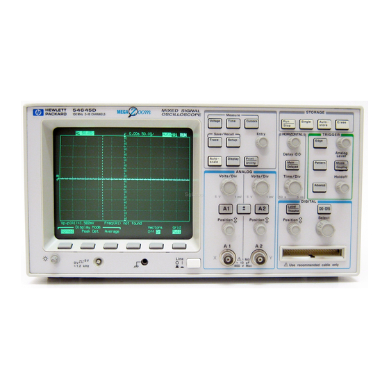
Front-Panel Overview HP 54645A/D Front Panels HP 54645A/D Front Panels Figure 2-1 Display Measurement Storage Trigger Keys Keys Keys Softkeys Brightness Calibration Channel Trigger Horizontal Power Control Output Inputs/ Input Controls Controls HP 54645A Oscilloscope Front Panel... - Page 32 Front-Panel Overview HP 54645A/D Front Panels Figure 2-2 Display Measurement Storage Trigger Keys Keys Keys Softkeys Brightness Calibration Horizontal Digital Channel Analog Channel Power Control Output Controls Inputs/Controls Inputs/Controls HP 54645D Mixed-Signal Oscilloscope Front Panel...
-
Page 33: Description Of Front-Panel Areas
Front-Panel Overview Description of Front-Panel Areas Description of Front-Panel Areas Table 2-1 HP 54645A Front-Panel Areas Front-Panel Areas Functions Control Knobs Display Shows waveforms, measurement results and instrument configuration settings. Softkeys Set up various options for each major function, varying dynamically depending on the required function. - Page 34 Front-Panel Overview Description of Front-Panel Areas Table 2-2 HP 54645D Front-Panel Areas Front-Panel Areas Functions Control Knobs Display Shows waveforms, measurement results and instrument configuration settings. Softkeys Set up various options for each major function, varying dynamically depending on the required function. General Controls Include various measurement functions, configuration, Entry...
- Page 35 Front-Panel Overview Description of Front-Panel Areas Table 2-3 HP 54645A/D Front-Panel Specifics General Description Applies to Unit: Front-Panel Areas Waveform Display The waveform display area shows all acquisition results. You HP 54645A/D can change the graticule or turn it off entirely using the Display menu.
- Page 36 Keypad and Softkeys Some keys, such as On/Off and Label also have special functions while in the menus that they activate. Keys on the HP 54645A/D front panels include the following: White keys have an immediate action, such as starting or HP 54645A/D stopping the instrument.
-
Page 37: Messages
The Entry knob selects from multiple choices in menus. It also HP 54645A/D occasionally duplicates the function of the Select knob. The Trigger Level knob (HP 54645A) and Trigger Analog Level HP 54645A/D knob (HP 54645D) sets the trigger level for stabilizing a waveform on the screen. - Page 38 Time/Div shows the time base setting. Time per division is HP 54645A/D variable from 2 ns/div to 50 s/div for HP 54645A, and from 5 ns/div to 50 s/div for HP 54645D. When Coupling is set to AC, a small sine wave is included in the HP 54645A/D top left area of the status line.
- Page 39 Front-Panel Areas Description Applies to Unit: Trigger condition shows the current trigger mode. The Auto HP 54645A/D Level and Auto trigger modes display the "Auto" indicator. For Edge trigger mode, it also shows the trigger condition and channel number. In normal trigger mode, when the TV trigger mode is selected, HP 54645A/D "TV"...
- Page 40 Front-Panel Areas Description Applies to Unit: Channel Numbers The channel numbers are always shown along the left edge of the HP 54645A/D display. Channel Labels You can assign channel labels to help you remember the function of HP 54645D only each channel in your circuit, or disable the labels to increase the waveform display area.
-
Page 41: Front-Panel Operation
HP 54645D Mixed-Signal Oscilloscope. Oscilloscope Channels are Labeled Differently On the HP 54645A Oscilloscope, the analog channels are labeled 1 and 2 since there are no digital channels. On the HP 54645D Mixed-Signal Oscilloscope, the analog channels are labeled A1 and A2 to distinguish them from the digital channels. -
Page 42: To Use Oscilloscope Channels To View A Signal
Setup Example Connect the oscilloscope probes for channels 1 and 2 for HP 54645A (or A1 and A2 for HP 54645D) to the calibrator output on the front panel of the instrument. Set the instrument to the factory default configuration by , then Default Setup. -
Page 43: To Use Digital Channels To View A Signal
Front-Panel Overview To use digital channels to view a signal To use digital channels to view a signal To configure the instrument quickly, press Autoscale To undo the effects of autoscale, press , then press Undo Setup Autoscale To set the instrument to the factory-default measurement configuration, press , then press Default Setup... -
Page 44: To Display Signals Automatically Using Autoscale
A scope channel is active if it is at least 10 mVp-p. Autoscale finds dc (> 50 mV) on the HP 54645A/D scope channels. The scope channels that are on are scaled vertically to best fit the screen. -
Page 45: To Apply The Default Factory Configuration
Front-Panel Overview To apply the default factory configuration During Autoscale, the delay is set to 0.0 seconds, the Time/Div setting is a function of the input signal (about 2 periods of the triggered signal on the screen), and the triggering mode is set to edge. The instrument stays in Normal or Peak Detect display mode, depending on what was selected when Autoscale was performed. -
Page 46: To Adjust Oscilloscope Vertical Scaling
Change the vertical sensitivity with the Volts/Div knob and notice that it causes the status line to change. Press (for HP 54645A) or (for HP 54645D). A softkey menu appears on the display, and the channel turns on (or remains on if it was already turned on). - Page 47 To turn the channel off, either press (for HP 54645A) or (for HP 54645D) a second time or press the left-most softkey. Invert Operating Hint Inversion affects how a channel is displayed, but it does not affect triggering.
- Page 48 Volts/Div setting. Oscilloscope Probes The HP 54645A/D Oscilloscopes have automatic probe sensing. If you are using the probes supplied with the oscilloscope, or other probes with probe sensing, the probe attenuation factor will be automatically set up by the oscilloscope when automatic probe sensing is turned on.
-
Page 49: To Turn Analog Channels On And Off
If you are already accessing the channel menu, you can press the On/Off key or the channel key (1 or 2 for HP 54645A; A1 or A2 for HP 54645D) to toggle a particular channel on or off. -
Page 50: To Turn Digital Channels On And Off (Hp 54645D)
Front-Panel Overview To turn digital channels on and off (HP 54645D) To turn digital channels on and off (HP 54645D) To turn digital channels 0 through 7 on, press , then D0-D15 press the softkey. To turn these channels off, press the D0 - D7 On Off softkey. -
Page 51: To Rearrange The Digital Channels (Hp 54645D)
Front-Panel Overview To rearrange the digital channels (HP 54645D) To rearrange the digital channels (HP 54645D) Turn the Select knob to choose the digital channel you want to move. Only channels that are currently on may be moved. Turn the Position knob to move the selected channel to a new position. -
Page 52: To Operate The Time Base Controls
Turn the Time/Div knob and notice the change it makes to the status line. The Time/Div knob changes the sweep speed from 2 ns to 50 s (HP 54645A) and from 5 ns to 50 s (HP 54645D) in a 1-2-5 step sequence, and the value is displayed in the status line. -
Page 53: To Start And Stop An Acquisition
Front-Panel Overview To start and stop an acquisition All events displayed left of the trigger point happened before the trigger occurred, and these events are called pre-trigger information. You will find this feature very useful because you can now see the events that led up to the trigger point. -
Page 54: To Use The Entry And Select Knobs
Front-Panel Overview To use the Entry and Select knobs To use the Entry and Select knobs The Select knob (HP 54645D only) always changes the selected channel. In most menus, its order is screen-oriented. In the simple pattern and advanced pattern definition menus, it moves from the lowest to highest number on clockwise rotation. -
Page 55: To Make Cursor Measurements
Cursors Source selects a channel for the voltage cursor measurements (1 and 2 for HP 54645A and A1 and A2 for HP 54645D). If a Measurement/Storage module is installed in the oscilloscope, and Function 2 is set to FFT and is turned on, you can select f1 or f2 for the source. - Page 56 Front-Panel Overview To make cursor measurements On HP 54645D, the Readout softkey gives a reading of the time or voltage cursor measurement. For the time cursor readout, you can select Time, Hex, Binary, or Degrees. Binary displays all digital channels by channel number. Hex shows only the displayed channels, with the top channel displayed as the most significant bit.
-
Page 57: To Use Delayed Sweep
Front-Panel Overview To use delayed sweep To use delayed sweep Delayed sweep is a magnified portion of the main sweep. You can use delayed sweep to locate and horizontally expand part of the main sweep for a more detailed (high-resolution) analysis of signals. The following steps show you how to use delayed sweep. -
Page 58: To Modify The Graticule
Front-Panel Overview To modify the graticule To modify the graticule Press Display Press one of the Grid softkeys to define the graticule used for the waveform area on the display. Frame has a set of hash marks along the top and bottom of the display only. Major divisions are indicated by longer hash marks. -
Page 59: To Print The Display
Front-Panel Overview To print the display To print the display You can print the waveform display and status line to an HP printer or Epson-compatible printer attached to one of these optional interface modules: HP 54650A HP-IB Interface Module HP 54652A Parallel Interface Module HP 54652B RS-232/Parallel Interface Module HP 54657A Measurement/Storage Module (HP-IB) HP 54659B Measurement/Storage Module (RS-232/Parallel) -
Page 60: Triggering Hp 54645A/D Oscilloscopes
Triggering HP 54645A/D Oscilloscopes... - Page 61 Triggering HP 54645A/D Oscilloscopes The HP 54645A/D Oscilloscopes provide a full set of features to help automate your measurement tasks, including MegaZoom technology to help you capture and examine the stored waveforms of interest, even untriggered waveforms. With these oscilloscopes you can: Modify the way the oscilloscope acquires data.
-
Page 62: Selecting Trigger Modes And Conditions
Selecting Trigger Modes and Conditions The trigger mode affects the way in which the oscilloscope searches for the trigger. Figure 3-1 shows the conceptual representation of acquisition memory. Think of the trigger event as dividing acquisition memory into a pre-trigger and post-trigger buffer. The position of the trigger event in acquisition memory is defined by the time reference point and the delay setting. - Page 63 Triggering HP 54645A/D Oscilloscopes To select a trigger mode: Auto Lvl, Auto, Normal When you select Single, the oscilloscope will fill acquisition memory, and continue flowing data through the pre-trigger buffer until the auto trigger overrides the searching and commands a trigger. At the end of the trace, the scope will stop and display the results.
-
Page 64: To Use Holdoff
The HP 54645A/D uses digital holdoff independent of time base settings. The advantage of digital holdoff is that it is a fixed number. As a result, changing the time base settings does not affect the holdoff number;... -
Page 65: To Trigger On A Complex Waveform
Triggering HP 54645A/D Oscilloscopes To trigger on a complex waveform To trigger on a complex waveform The difficulty in viewing a complex waveform is triggering on the signal. The simplest trigger method is to trigger the oscilloscope on a sync pulse that is associated with the waveform. -
Page 66: Triggering The Hp 54645A Oscilloscope
To use external triggering The external trigger input is only available on the HP 54645A Oscilloscope. Connect a signal to the BNC labeled “External Trigger”. The external trigger input has an input impedance of 1 M , and can accept a maximum signal of 400 V (dc + peak ac) with a range of 18 V. -
Page 67: To Trigger On An Edge
Slope/Glitch Select either the rising edge or falling edge softkey to choose whether the trigger will occur on the rising or falling edge of the input signal. Figure 3-2 HP 54645A Triggered on Rising Edge of Channel 2... -
Page 68: To Use Glitch Triggering
Triggering HP 54645A/D Oscilloscopes To use glitch triggering To use glitch triggering Press . Then select Glitch. Slope/Glitch Select Glitch Menu. Define the polarity, duration qualifier, and duration time for the glitch. Figure 3-3 HP 54645A Triggered on Glitch on Channel 1... -
Page 69: To Use Line Triggering
Triggering HP 54645A/D Oscilloscopes To use line triggering To use line triggering Press . Then select Line. Source To use TV triggering Press . Select 1 or 2 for the Trigger Source channel. Source Press . Then select Slope/Glitch Select TV Menu. -
Page 70: Triggering The Hp 54645D Mixed-Signal Oscilloscope
Triggering the HP 54645D Mixed-Signal Oscilloscope The HP 54645D Mixed-Signal Oscilloscope allows you to synchronize the oscilloscope display to the actions of the circuit under test by defining a trigger condition. The trigger types include edge, pattern, and advanced, allowing you to match the complexity of the trigger to that of the data you want to capture. -
Page 71: Trigger Types
Triggering HP 54645A/D Oscilloscopes Trigger types Trigger types These trigger types are available: Edge trigger Pattern trigger Advanced trigger Changes to the trigger specification are applied when you make them. If the oscilloscope is stopped when you change a trigger specification, the scope will use the new specification when you press Run/Stop, Single, or Autostore. - Page 72 Triggering HP 54645A/D Oscilloscopes Trigger types Glitch Trigger The advanced glitch trigger menu lets you select the analog (A1 or A2) or digital (D0-D15) channel on which to capture a glitch event. You specify the polarity and duration qualifier—either less than (<), greater than (>), or a range—for the glitch.
- Page 73 Triggering HP 54645A/D Oscilloscopes Trigger types Specifying a Logic Threshold You can specify a threshold for the logic channels. See “To change the logic threshold for input signals” in chapter 4 for information about setting a threshold on the HP 54645D.
- Page 74 Triggering HP 54645A/D Oscilloscopes Trigger types Sharing of Sources The source definitions for the simple pattern trigger are shared with the Pattern 1 and Edge 1 sources of the advanced pattern trigger specification. Thus, changes to the simple pattern trigger will affect that specification, and changes to Pattern 1 and Edge 1 in the advanced pattern trigger specification will affect the simple pattern trigger.
-
Page 75: To Define An Edge Trigger
Triggering HP 54645A/D Oscilloscopes To define an edge trigger To define an edge trigger Press Edge Select a channel as the trigger source using either the Select knob or by pressing a softkey. Trigger Source You can choose a channel that is turned off as the source for the edge trigger. -
Page 76: To Define A Pattern Trigger
Triggering HP 54645A/D Oscilloscopes To define a pattern trigger To define a pattern trigger Press Pattern For each analog channel (A1 or A2) or digital channel (D0-D15) you want to include in the desired pattern, press the softkey to Source select the channel, or rotate the Entry knob or the Select knob. -
Page 77: To Use Glitch Triggering
Triggering HP 54645A/D Oscilloscopes To use glitch triggering To use glitch triggering Press . Then select Glitch. Advancd Select Glitch Menu. Select the analog channel (A1 or A2) or digital channel (D0-D15) source for the trigger by pressing the softkey until the desired Source source is highlighted. -
Page 78: To Define An Advanced Pattern Trigger
Triggering HP 54645A/D Oscilloscopes To define an advanced pattern trigger To define an advanced pattern trigger The advanced triggering operation depends on previous selections in the Advanced Trigger menu. Press . Then select Pattern. Advancd Press the Overview softkey to turn on the trigger overview, if desired. - Page 79 Triggering HP 54645A/D Oscilloscopes To define an advanced pattern trigger Select the source(s) for the trigger operator by pressing the leftmost Source softkey until the desired source is highlighted. Refer to the table of trigger operators and sources to see the sources and operators with which they can be used.
- Page 80 Triggering HP 54645A/D Oscilloscopes To define an advanced pattern trigger To set up a pattern trigger source, do the following: Select a channel for the source. To set the condition for that channel, press the L, H, or X softkey.
- Page 81 Triggering HP 54645A/D Oscilloscopes To define an advanced pattern trigger Setup rules Remembering the following rules will make it easier to work with the advanced triggering capabilities: Duration operators are valid when only pattern terms are involved. Duration is not selectable when any edge term is selected as a source.
- Page 82 Triggering HP 54645A/D Oscilloscopes To define an advanced pattern trigger Example Suppose you have a pulse train where one of the pulses is of constant duration (4 s) and all other signals of interest are repeated with that pulse train, as shown in the following figure.
- Page 83 Triggering HP 54645A/D Oscilloscopes To define an advanced pattern trigger Source Operator and Pattern/Edge Parameters Pattern 1 Then L on channels D2, D1, and D0, others don’t care Pattern 2 L on channels 2 and 1, H on channel 0, others don’t care...
-
Page 84: Megazoom Concepts And Oscilloscope Operation
MegaZoom Concepts and Oscilloscope Operation... - Page 85 Oscilloscopes with HP’s MegaZoom Technology The information in this chapter applies to both the HP 54645A and HP 54645D Oscilloscope models because both are based on HP’s MegaZoom technology.
-
Page 86: Megazoom Concepts
MegaZoom Technology’s Deep Memory Improves Timing Resolution The HP MegaZoom technology used in the HP 54645A/D oscilloscopes keeps the sampling rate at the maximum for all sweep speeds of 500 s/div and faster in... -
Page 87: Deep Memory
MegaZoom Concepts Deep Memory Deep Memory The primary advantage of a deep-memory oscilloscope is sustained sample rate, allowing you to capture at the maximum sample rate and capture a much longer time window. For example, you may want to capture a fast digital event, such as an interrupt line being asserted, while being able to look far out in time to see when the line was de-asserted. -
Page 88: Oscilloscope Responsiveness
MegaZoom Concepts Oscilloscope Responsiveness Oscilloscope Responsiveness An important element of an oscilloscope is how responsive it is to control changes. After a control is changed, such as the time/division, if you must wait for the test instrument to respond, the feedback loop between the instrument and you can become difficult. -
Page 89: Display Update Rate
MegaZoom Concepts Display Update Rate Display Update Rate In analog oscilloscopes, the scope is “blind” while the electron beam is reset to the left side of the screen. Thus, the update rate of an analog scope seems high because the blind or dead time of the analog scope is low. High update rate is advantageous because infrequent or random events that happen while the scope is blind are missed, and thus not displayed. -
Page 90: Display Modes
You should set it to a level that makes for comfortable viewing, given the room lighting, and keep it there. In the HP 54645A/D, you control the “detail” by selecting a display mode: Normal, Peak Detect, or Average. While you may want to change the display mode now and then, rest assured that you will not have to change it nearly as often as you adjusted the brightness of an analog scope. - Page 91 In the case of the HP 54645A/D, the analog channels can have up to 1 million samples behind the 4,000-point scope display. Some compression of samples to display points is obviously necessary.
- Page 92 MegaZoom Concepts Display Modes Figure 4-1 Attempting to Capture Narrow Pulse As you change the Time/Div setting (zoom in), and look at a smaller time window around the trigger, the percentage of the acquired samples to the displayed samples increases. For example, at 2 s/div (20 s/div across the screen), we now display every sample acquired in that time window (20 s / 5 ns = 4,000 samples).
- Page 93 MegaZoom Concepts Display Modes Between the 500- s/div picture (figure 4-1), and the 2- s/div picture (figure 4-2), whether or not the pulse or some part of the pulse is displayed is simply a statistical problem. For every new sweep speed, a new ratio of displayed-versus-sample points is necessary to provide the “best”...
- Page 94 Peak Detection Prevents Aliasing Aliasing produces misleading information. The peak detection circuitry in the HP 54645A/D helps to prevent aliasing by identifying additional transitions that occur between logic samples. Because of the high sample rate of the HP 54645A/D MegaZoom technology, you should not see aliasing.
- Page 95 Figure 4-4 Same Square Wave in Peak Detect Mode at 200 s/div on HP 54600 The HP 54645A/D goes one step further in peak detect mode. In addition to the maximum and minimum values, the HP 54645A/D includes some “normal”...
- Page 96 Changing Display Modes While Stopped One of the benefits of the HP 54645A/D is that you can change display modes after you acquire data. You can switch from peak detect to normal display mode.
- Page 97 MegaZoom Concepts Display Modes Peak Detect versus Normal on HP 54645D Digital Channels In a digital system design, a glitch is an unintentional or unexpected signal transition which may or may not pass through the logic threshold. The HP 54645D supports capturing glitches on digital channels during data acquisition.
- Page 98 MegaZoom Concepts Display Modes Average Mode Averaging is a way to pull the signal out of the noise. Averaging works better than either a bandwidth limit or a brightness control. The averages you can select include "Smoothing", 4, 8, 16, 32, 64, 128, and 256. Smoothing is an oversampling technique, and operates as described in the “Display Modes”...
- Page 99 Complex analog signals like video and eye diagrams show more intensity information with vectors off. One of the benefits of the HP 54645A/D is that you can change display modes after you acquire data. You can turn vectors on and off, or switch from peak detect to normal display modes.
- Page 100 MegaZoom Concepts Display Modes Displaying Analog Channels After the Acquisition The two scope channels are always acquired, so you can turn them on and look at them even if they were off during the acquisition. You can do math functions on channels that are turned off, but you cannot make measurements on them.
-
Page 101: Pan And Zoom
MegaZoom Concepts Pan and Zoom Pan and Zoom The ability to pan (move horizontally) and zoom (expand or compress horizontally) an acquired waveform is important because of the additional insight it can reveal about the captured waveform. This additional insight is often gained from seeing the waveform at different levels of abstraction. - Page 102 Vertically, the box indicates the maximum and minimum value. These boxes apply to both digital channels on the HP 54645D and analog channels on the HP 54645A/D. These boxes also indicate that the scope could get better timing resolution if you re-acquired the data at a faster sweep speed.
- Page 103 Normal point Resolution Limit in Peak Detect with Vectors Off Recall that in peak detect, the HP 54645A/D shows both peak detect information and some “normal” points. In this figure, horizontal lines indicate both the time over which the max and min values were searched (line length) and the max and min values (line position—the upper line corresponds to the...
-
Page 104: Recovering The Waveform On The Screen
MegaZoom Concepts Recovering the waveform on the screen Recovering the waveform on the screen In the HP 54645A/D, pressing freezes the screen. When Run/Stop either of the following occur, there will be several triggers of information on the screen. The scope is running at fast sweep speeds (1 s/div and faster). -
Page 105: Changing The Time Reference Position
MegaZoom Concepts Changing the time reference position Changing the time reference position Press Main/Delayed Choose the time reference position from the Time Reference softkeys: To set the time reference so that most of the acquired data follows the trigger, press Left. The time reference indicator will be one division in from the left side of the display. - Page 106 MegaZoom Concepts Changing the time reference position The time reference position sets the initial position of the trigger event within acquisition memory and on the display, with delay set to 0. The delay setting sets the specific location of the trigger event with respect to the time reference position.
- Page 107 MegaZoom Concepts Changing the time reference position At 5 s/div, we are sampling at 200 MSa/s (scope), and 400 MSa/s (digital). When no delay value is set, and the time reference is set to Center, the trigger point is displayed at the center of the screen. Consider a measurement where we want to view a signal from 30 s before the trigger point, and 30 s after the trigger point.
- Page 108 MegaZoom Concepts Changing the time reference position When we pan the display (move it horizontally) back and set the delay to 15 s, the trigger point is displayed on the screen. The part of the signal we see displayed at the center of the screen is to the right of the trigger point. The result resembles: Figure 4-10 The trigger event...
- Page 109 MegaZoom Concepts Changing the time reference position Setting a negative delay lets us look at the part of the signal to the left of the trigger point. Suppose we set the time reference to Right, with a sweep speed of 5 s, and a delay value of -30 s. When we perform a single acquisition, the display resembles: Figure 4-11 The trigger event...
- Page 110 MegaZoom Concepts Changing the time reference position If we set the time reference to center, then pan the display back to set the delay to 0 s, the trigger point is displayed at center screen, and the result resembles: Figure 4-12 Panning the Display to View the Trigger Point Here, the trigger point is in memory.
- Page 111 (the resolution increases). One of the benefits of the HP 54645A/D is that you can change display modes after you acquire data. You can turn vectors on/off, or switch from peak detect to normal display modes.
-
Page 112: Run/Stop/Single/Autostore/Erase Operation
If the voltage is above the threshold, the oscilloscope stores a “1” in sample memory; otherwise, it stores a “0.” To control the HP 54645A/D acquisition process, you can do the following: Perform continuous acquisitions by pressing the Run/Stop key, and stop the acquisitions by pressing Run/Stop again. -
Page 113: Acquiring Data
Run/Stop/Single/Autostore/Erase Operation Acquiring Data Acquiring Data The HP 54645A/D operates like an analog scope, but it can do much more. Spending a few minutes to learn some of this capability will take you a long way toward more productive troubleshooting. -
Page 114: Memory Depth/Record Length
Memory Depth/Record Length Run/Stop versus Single The HP 54645A/D both have a Single key and a Run/Stop key. When you press Run, the trigger processing or update rate is optimized over memory depth. When you press Single, memory depth is maximized. - Page 115 Run/Stop/Single/Autostore/Erase Operation Memory Depth/Record Length Given that this is the case, we now have two options: We could acquire a full 500,000 points for every acquisition, resulting in some samples being “off screen.” We could decrease the acquired record size, only filling a fraction of the available 500,000 points.
-
Page 116: To Run And Stop An Acquisition
Run/Stop/Single/Autostore/Erase Operation To run and stop an acquisition To run and stop an acquisition To begin an acquisition, press the key. Run/Stop The instrument begins acquiring data while searching for a trigger condition. The RUN indicator is shown in the upper-right corner of the display. If a trigger occurs, the acquired data is shown in the display. -
Page 117: To Capture A Single Event
TTL logic, a trigger level of 2 volts should work on a rising edge. These steps show you how to use the oscilloscope to capture a single event. Connect a signal to the oscilloscope. For HP 54645A, set up the trigger. Press . Select a trigger source. - Page 118 Run/Stop/Single/Autostore/Erase Operation To capture a single event Press Single Pressing arms the trigger circuit. When the trigger conditions Single are met, data appears on the display, representing the data points that the oscilloscope obtained with one acquisition. Pressing again re-arms the trigger circuit and erases the display. Single Operating Hints When Trigger Mode is set to Auto or Auto Lvl (auto-single mode), each...
-
Page 119: To Use Autostore
Run/Stop/Single/Autostore/Erase Operation To use Autostore To use Autostore With Autostore or infinite persistence, the scope updates the display with new acquisitions, but does not erase the results of previous acquisitions. Rather than being erased by subsequent acquisitions, each pixel memory location turned on by a previous acquisition is turned into a pixel in half-bright. -
Page 120: To Autostore Multiple Single Events
Run/Stop/Single/Autostore/Erase Operation To Autostore Multiple Single Events To Autostore Multiple Single Events To Autostore single events, you first need to configure the instrument to do single Autostores. Press to put the instrument in Autostore mode. Autostore This causes the instrument to run. Press to take a single autostored acquisition. -
Page 121: To Erase The Waveform Display
Run/Stop/Single/Autostore/Erase Operation To erase the waveform display To erase the waveform display Press Erase Acquisition memory and the current display are immediately erased. If the instrument is in Run or Autostore mode, however, and the oscilloscope finds a trigger condition, the display will be quickly updated after the erasure. Summary of Oscilloscope Storage Keys Run—acquires data and displays the most recent trace. -
Page 122: Using Digital Channels To Probe Circuits
Run/Stop/Single/Autostore/Erase Operation Using Digital Channels to Probe Circuits Using Digital Channels to Probe Circuits You may encounter problems when using the HP 54645D that are related to probing. These problems fall into two categories: probe loading and probe grounding. Probe loading problems generally affect the circuit under test, while probe grounding problems affect the accuracy of the data to the measurement instrument. - Page 123 Run/Stop/Single/Autostore/Erase Operation Using Digital Channels to Probe Circuits Figure 4-14 High-Frequency Probe Equivalent Circuit The impedance plots for the two models are shown in these figures. By comparing the two plots, you can see that both the series tip resistor and the cable’s characteristic impedance extend the input impedance significantly.
- Page 124 Run/Stop/Single/Autostore/Erase Operation Using Digital Channels to Probe Circuits Probe Grounding A probe ground is the low-impedance path for current to return to the source from the probe. Increased length in this path will, at high frequencies, create large common mode voltages at the probe input. The voltage generated behaves according to the equation: Increasing the ground inductance (L), increasing the current (di) or decreasing the transition time (dt), will all result in increasing the voltage...
- Page 125 Run/Stop/Single/Autostore/Erase Operation Using Digital Channels to Probe Circuits In addition to the common mode voltage—ground bounce—longer ground returns also degrade the pulse fidelity of the probe system. Risetime is increased, and ringing, due to the undamped LC circuit at the input of the probe, is also increased.
-
Page 126: Saving And Recalling The Configuration
Trace memory Two trace memories, also called pixel memories, are available in the HP 54645A/D. These allow you to save the visible portion of the acquisition—the displayed waveform—for later recall and comparison with other measurements. To ensure repeatability of the measurement, should you decide to repeat it after recalling a result from trace memory, the setup is saved with the waveform, and can be independently recalled. - Page 127 Trace Memory Softkeys on HP 54645D with HP 54659B Measurement/Storage Module Installed Setup memory The HP 54645A/D has 10 separate setup memories that allow you to save the current configuration of the instrument, including time base, threshold, channel settings, measurement definitions, and, for the HP 54645D, labels (not as independent label lists).
- Page 128 Saving and Recalling the Configuration Using memories to save and recall configurations For example, suppose that you use the HP 54645A/D in field testing of a system where ten separate tests are used. You can predefine the test configurations and save them in setup memories 1-10. You might also record the expected results as part of field test documentation.
-
Page 129: To Save, Recall, And Clear Traces
Saving and Recalling the Configuration To save, recall, and clear traces To save, recall, and clear traces To save traces, two trace memories are available. The following exercise shows you how to store and recall waveforms from pixel memories. Connect a signal to the oscilloscope and obtain a stable display. Press Trace A softkey menu appears with trace memory selections. - Page 130 Saving and Recalling the Configuration To save, recall, and clear traces Select a trace memory by pressing the softkey. Trace Press the Save to Mem<N> softkey. The current oscilloscope screen and setup are copied to the selected trace memory. Press the Trace Mem On softkey to display memory.
-
Page 131: To Save Or Recall Front-Panel Setups
Press the softkey to save a front-panel setup, then press the Save softkey to recall a front-panel setup. Recall To reset the HP 54645A/D instrument setup To reset the instrument to the default factory-preset configuration, press Setup Press the Default Setup softkey. - Page 132 Saving and Recalling the Configuration To reset the HP 54645A/D instrument setup Table 4-1 HP 54645A Factory-Preset Default Configuration Settings Configuration Item Setting Cursors Cursors off; time readout is selected; all cursors are set to time/voltage zero. Trace memories Both trace memory 1 and 2 are off; trace 1 memory is selected.
- Page 133 Saving and Recalling the Configuration To reset the HP 54645A/D instrument setup Table 4-2 HP 54645D Factory-Preset Default Configuration Settings Configuration Item Setting Cursors Cursors off; time readout is selected; all cursors are set to time/voltage zero Trace memories Both trace memory 1 and 2 are off; trace 1 memory is selected...
-
Page 134: Configuring The Mixed-Signal Oscilloscope
Configuring the Mixed-Signal Oscilloscope This section describes how to configure the following items for the HP 54645D Mixed-Signal Oscilloscope, including changing the logic threshold for input signals. To change the logic threshold for input signals Press Label/Threshold Press the Threshold Menu softkey to display the range of channels for which you want to set the logic threshold, and the available logic thresholds. - Page 135 Configuring the Mixed-Signal Oscilloscope To change the logic threshold for input signals Figure 4-19 Variable threshold softkey Logic Threshold Setup The threshold voltage setting is used by the input comparators to determine whether an input signal is a logic low or logic high. The settings for each option are shown in the following table.
-
Page 136: Using Labels On The Mixed-Signal Oscilloscope
Using Labels on the Mixed-Signal Oscilloscope The HP 54645D Mixed-Signal Oscilloscope allows you to define and assign labels to each input channel. Or, you can turn labels off to increase the waveform display area. To turn the label display on or off To display channel labels, press , then press Label/Threshold... -
Page 137: To Assign A Predefined Label To A Channel
Using Labels on the Mixed-Signal Oscilloscope To assign a predefined label to a channel To assign a predefined label to a channel Press Label/Threshold Press the Define Labels softkey. The following figure shows the label maker. A label definition menu is shown on the right-hand side of the display. - Page 138 Using Labels on the Mixed-Signal Oscilloscope To assign a predefined label to a channel If you defined a new label, it is added to the non-volatile label list and will be saved with the oscilloscope configuration. Figure 4-20 Scroll through the The entry field shows you label and character what will be assigned to...
-
Page 139: To Define A New Label
Using Labels on the Mixed-Signal Oscilloscope To define a new label Label List Management The label list contains 75 of the most recently used labels. The list does not save duplicate labels, nor does it save multiple labels that differ by, at most, two trailing numeric characters. - Page 140 Using Labels on the Mixed-Signal Oscilloscope To define a new label To enter characters into the new label: Press the Position softkey until the cursor position in the entry field corresponds to the point where you want to replace a character. Enter or delete a character.
-
Page 141: To Initialize The Label List
Using Labels on the Mixed-Signal Oscilloscope To initialize the label list To initialize the label list Press Label/Threshold Press the Initialize Label List softkey. A message appears, warning you that this operation will overwrite the current label list. To confirm the operation, press the Yes softkey. You will be prompted to press Yes again to initiate the operation. -
Page 142: Making Measurements With Hp 54645A/D Oscilloscopes
Making Measurements with HP 54645A/D Oscilloscopes... - Page 143 We recommend you perform all of the following exercises so you become familiar with the powerful measurement capabilities of the oscilloscope. Concepts about the HP 54645A/D Oscilloscopes Conceptual information about the HP 54645A/D Oscilloscopes is in the chapter “MegaZoom Concepts and Oscilloscope Operation.”...
-
Page 144: Capturing Data
2 ns/div for HP 54645A and 5 ns/div for HP 54645D. For example, at a main time base setting of 500 s/div, the delayed sweep time base will be... -
Page 145: To Use Delayed Sweep
Making Measurements with HP 54645A/D Oscilloscopes To use delayed sweep To use delayed sweep You can use the delayed sweep window to locate and horizontally expand part of the main sweep for a more detailed (high-resolution) analysis of signals. The following steps show you how to use delayed sweep. These steps are similar to operating the delayed sweep in analog oscilloscopes. - Page 146 Making Measurements with HP 54645A/D Oscilloscopes To use delayed sweep The screen divides in half. The top half displays the main sweep, and the bottom half displays an expanded portion of the main sweep. This expanded portion of the main sweep is called the delayed sweep. The top half also has two solid vertical lines called markers.
-
Page 147: To View Asynchronous Noise On A Signal
Making Measurements with HP 54645A/D Oscilloscopes To view asynchronous noise on a signal To view asynchronous noise on a signal The following exercise shows how to use the oscilloscope to view asynchronous noise on a signal that is not synchronous to the period of the waveform. - Page 148 Making Measurements with HP 54645A/D Oscilloscopes To view asynchronous noise on a signal Press Autostore Notice that is displayed in the status line. STORE Set the trigger mode to normal, then adjust the trigger level into the noise region of the signal.
-
Page 149: To Reduce The Random Noise On A Signal
Making Measurements with HP 54645A/D Oscilloscopes To reduce the random noise on a signal To reduce the random noise on a signal If the signal you are applying to the oscilloscope is noisy, you can set up the oscilloscope to reduce the noise on the waveform. First, you stabilize the displayed waveform by removing the noise from the trigger path. - Page 150 Making Measurements with HP 54645A/D Oscilloscopes To reduce the random noise on a signal Low-frequency reject (LF reject) adds a high-pass filter with the 3-dB point at 50 kHz. Use LF reject to remove low-frequency signals, such as power line noise, from the trigger path.
- Page 151 Making Measurements with HP 54645A/D Oscilloscopes To reduce the random noise on a signal Use averaging to reduce noise on the displayed waveform. , then press Average. Press Display Notice that appears in the status line. Toggle the # Average softkey to select the number of averages that best eliminates the noise from the displayed waveform.
-
Page 152: To Capture Glitches Or Narrow Pulses With Peak Detect
Making Measurements with HP 54645A/D Oscilloscopes To capture glitches or narrow pulses with peak detect To capture glitches or narrow pulses with peak detect A glitch is a rapid change in the waveform that is usually narrow as compared to the waveform. -
Page 153: To Use Channel Math
To turn off the channel math function, press the Off softkey. Additional Math Functions For the HP 54645A/D Oscilloscopes, without a Measurement/Storage module installed, the available math options are addition and subtraction. Each of these functions is performed on the pixel position of the data on the screen. -
Page 154: To Use The Roll Display Mode
Making Measurements with HP 54645A/D Oscilloscopes To use the Roll display mode With the Measurement/Storage module installed, two functions define these operations that create mathematically altered waveforms (not pixel math): Function 1 will add, subtract, or multiply the signals acquired on vertical inputs 1 and 2, then will display the result as F1. -
Page 155: To Use The Xy Display Mode
, then press the Autoscale Main/Delayed softkey. Center the signal on the display with the Vertical Position (HP 54645A) or Analog Position (HP 54645D) knobs, and use the Volts/Div knobs and the vertical softkeys to expand the signal Vernier for convenient viewing. - Page 156 Making Measurements with HP 54645A/D Oscilloscopes To use the XY display mode Figure 5-9 Signal Centered on the Display Press Cursors Set the Y2 cursor to the top of the signal, and set Y1 to the bottom of the signal.
- Page 157 X-axis input, channel 2 is the Y-axis input, and the external trigger in the HP 54645A is the Z-axis input. If you only want to see portions of the Y versus X display, use the Z-axis input. Z-axis turns on and off the trace (analog oscilloscopes called this Z-blanking because it turned the beam on and off).
- Page 158 Making Measurements with HP 54645A/D Oscilloscopes To use the XY display mode Figure 5-12 Signals are 90° Out of Phase Figure 5-13 Signals are In Phase 5-17...
-
Page 159: To Analyze Video Waveforms
Making Measurements with HP 54645A/D Oscilloscopes To analyze video waveforms To analyze video waveforms The TV sync separator in the oscilloscope has an internal clamp circuit. This removes the need for external clamping when you are viewing unclamped video signals. TV triggering requires two vertical divisions of display, either channel 1 or channel 2 as the trigger source, and the selection of internal trigger. - Page 160 Making Measurements with HP 54645A/D Oscilloscopes To analyze video waveforms Set the time base to 200 s/div, then center the signal on the display with the Delay knob (delay about 800 s). Press , then press the Delayed softkey. Pan and Main/Delayed zoom the waveform to view signal details.
- Page 161 Making Measurements with HP 54645A/D Oscilloscopes To analyze video waveforms , then press the Main softkey. Press Main/Delayed Use the horizontal vernier to change the time base to 1 s/div, then center the signal on the display with the Delay knob (delay about 901 s).
- Page 162 This allows you to view noninterlaced video signals which are common in today’s computer monitors. To trigger on both sync pulses, press Field 1 and Field 2 at the same time, or press Vertical (HP 54645A). TV Trigger Operating Hints The color burst never really changes phase, it just looks doubled triggered because its frequency is an odd multiple of one half the line frequency.
-
Page 163: Measuring Waveform Data
Measuring Waveform Data With the HP 54645A/D Oscilloscopes, you can measure waveform data using Voltage, Time, and Cursor keys. This section shows you how. To make cursor measurements The following steps guide you through the front-panel Cursors key. You can use the cursors to make custom voltage or time measurements on the signal. - Page 164 Making Measurements with HP 54645A/D Oscilloscopes To make cursor measurements Use the Entry knob to move the cursors. You can toggle the active cursor by pressing the cursor key while in the cursors menu. Cursor measurements are not bound to the edge of the screen. If you set a cursor, then pan and zoom the waveform until that cursor is off the screen, when you set the other cursor, the measurement will still be accurate.
- Page 165 Making Measurements with HP 54645A/D Oscilloscopes To make cursor measurements Figure 5-18 Cursors Track Delayed Sweep Expand the display with delayed sweep, then characterize the event of interest with the cursors. 5-24...
- Page 166 Making Measurements with HP 54645A/D Oscilloscopes To make cursor measurements Figure 5-19 Moving Cursors Together Pressing the time cursor softkey until both time cursors are highlighted allows you to move them together when rotating the Entry knob. Figure 5-20 Checking Pulse Width Variations Move the cursors together to check for pulse width variations in a pulse train.
-
Page 167: To Make Frequency Measurements Automatically
The oscilloscope automatically measures the frequency and displays the result on the lower line of the display. The number in parentheses after the word Freq, for example Freq(1) for HP 54645A, or Freq(A1) for HP 54645D, shows the channel number (1 or A1) used for the measurement. - Page 168 Making Measurements with HP 54645A/D Oscilloscopes To make frequency measurements automatically To find the Show Meas softkey, press the Next Menu softkey key. When the Show Meas softkey is turned on, cursors are displayed on the waveform, and show measurement points for the measurement result displayed on the right-most part of the status line.
-
Page 169: To Make Time Measurements Automatically
Making Measurements with HP 54645A/D Oscilloscopes To make time measurements automatically To make time measurements automatically You can measure the following time parameters with the oscilloscope: frequency, period, duty cycle, positive and negative widths, rise time, and fall time. The following exercise guides you through the time keys by making a rise-time measurement. - Page 170 Making Measurements with HP 54645A/D Oscilloscopes To make time measurements automatically Press Time The first softkey menu appears with frequency, period, and duty cycle measurement choices. Source selects channel 1 or 2 for the time measurement. Time Measurements include frequency, period, and duty cycle. These measurements are made at the 50% levels.
- Page 171 Making Measurements with HP 54645A/D Oscilloscopes To make time measurements automatically Press the Rise Time softkey. The oscilloscope automatically measures the rise time of the signal and displays the result on the display. Automatic Measurements The oscilloscope makes automatic measurements on the first displayed event.
- Page 172 Making Measurements with HP 54645A/D Oscilloscopes To make time measurements automatically To measure the duty cycle Press Next Menu until you find the Duty Cy softkey, and press it. To measure the pulse widths To measure the positive pulse width, press Next Menu until you find the +Width softkey, and press it.
-
Page 173: To Make Voltage Measurements Automatically
Making Measurements with HP 54645A/D Oscilloscopes To make voltage measurements automatically To make voltage measurements automatically You can measure the following voltage parameters automatically with the oscilloscope: peak-to-peak, average, rms, maximum, minimum, top, base, amplitude, overshoot, and preshoot. The following exercise guides you through the Voltage keys by making an rms voltage measurement. - Page 174 Making Measurements with HP 54645A/D Oscilloscopes To make voltage measurements automatically Voltage Measurements Voltage measurements do not work on digital channels on HP 54645D. Connect a signal to the oscilloscope and obtain a stable display. Press Voltage A softkey menu appears with voltage measurement choices.
- Page 175 Making Measurements with HP 54645A/D Oscilloscopes To make voltage measurements automatically Figure 5-27 Isolating Area for Vtop Voltage Measurement Press the softkey. Next Menu A softkey menu appears with additional voltage measurement choices. Show Meas (show measurement) displays the horizontal and vertical cursors showing where the measurement was taken.
-
Page 176: Using Option 005 Enhanced Tv/Video Trigger (Hp 54645A)
Using Option 005 Enhanced TV/Video Trigger (HP 54645A) - Page 177 TV/Video Trigger You can use the Option 005 Enhanced TV/Video trigger with the HP 54645A Oscilloscope. One of the first things you will want to do with your oscilloscope’s new Option 005 Enhanced TV/Video trigger is to become acquainted with its menu choices. Therefore, we have written the exercises in this chapter to familiarize you with its basic controls.
- Page 178 Using Option 005 Enhanced TV/Video Trigger (HP 54645A) Option 005 gives you an Enhanced TV/Video Trigger for the HP 54645A Oscilloscope, allowing highly detailed analysis of TV waveforms. This option offers: NTSC, PAL, PAL-M, SECAM and generic video formats Video autoscale...
-
Page 179: To Autoscale On A Video Signal
Using Option 005 Enhanced TV/Video Trigger (HP 54645A) To autoscale on a video signal To autoscale on a video signal Use a cable to connect a TV signal to channel 1. Press in the section of the front panel, TRIGGER... -
Page 180: To Trigger On A Specific Line Of Video
Using Option 005 Enhanced TV/Video Trigger (HP 54645A) To trigger on a specific line of video To trigger on a specific line of video TV triggering requires greater than 1/4 division of sync amplitude, either channel 1 or channel 2 as the trigger source. Turning the trigger level knob in TV trigger does not change the trigger level because the trigger level is automatically set to the sync pulse tips. - Page 181 Using Option 005 Enhanced TV/Video Trigger (HP 54645A) To trigger on a specific line of video Figure 6-1 Triggering on Line 71 Note the TV Grid displayed (selected from the Display menu). Table 6-1 Line Numbers per Field for Each TV Standard...
-
Page 182: To Trigger On All Tv Line Sync Pulses
Using Option 005 Enhanced TV/Video Trigger (HP 54645A) To trigger on all TV line sync pulses To trigger on all TV line sync pulses To quickly find maximum video levels, you could trigger on all TV line sync pulses. When All Lines is selected as the TV trigger mode, the oscilloscope will trigger on the first line that it finds when the acquisition starts. -
Page 183: To Trigger On A Specific Field Of The Video Signal
Using Option 005 Enhanced TV/Video Trigger (HP 54645A) To trigger on a specific field of the video signal To trigger on a specific field of the video signal To examine the components of a video signal, trigger on either Field 1 or Field 2. -
Page 184: To Trigger On All Fields Of The Video Signal
Using Option 005 Enhanced TV/Video Trigger (HP 54645A) To trigger on all fields of the video signal To trigger on all fields of the video signal To quickly and easily view transitions between fields, or to find the amplitude differences between the fields, use the All Fields trigger. The oscilloscope will trigger on the first field it finds at the start of acquisition. -
Page 185: To Trigger On Odd Or Even Fields
Using Option 005 Enhanced TV/Video Trigger (HP 54645A) To trigger on odd or even fields To trigger on odd or even fields To check the envelope of your video signals, or to measure worst case distortion, trigger on the odd or even fields. When Field 1 is selected, the oscilloscope triggers on color fields 1 or 3. - Page 186 Using Option 005 Enhanced TV/Video Trigger (HP 54645A) To trigger on odd or even fields If a more detailed analysis is required, then only one color field should be selected to be the trigger. You can do this by using the oscilloscope’s holdoff control.
-
Page 187: To Analyze Video Waveforms With Option 005
Using Option 005 Enhanced TV/Video Trigger (HP 54645A) To analyze video waveforms with Option 005 To analyze video waveforms with Option 005 The combination of the TV trigger, delayed sweep, and automatic measurements allow this oscilloscope to precisely analyze video waveforms. - Page 188 Using Option 005 Enhanced TV/Video Trigger (HP 54645A) To analyze video waveforms with Option 005 Set the time base to 200 s/div, then center the signal on the display with the delay knob (delay about 800 s). Press , then press the softkey.
- Page 189 6-14...
-
Page 190: Testing, Adjusting, And Troubleshooting
Testing, Adjusting, and Troubleshooting... - Page 191 Testing, Adjusting, and Troubleshooting This chapter explains the general procedures for solving problems, verifying correct oscilloscope operation, adjusting the oscilloscope display and power supply, correcting malfunctions in the oscilloscope, and performing tests to ensure that the oscilloscope meets performance specifications. It also describes how to verify operation of the Option 005 Enhanced TV/Video Trigger board, along with information for adjusting the offset, and troubleshooting.
-
Page 192: Solving Problems With Hp 54645A/D Oscilloscopes
Solving Problems with HP 54645A/D Oscilloscopes This chapter describes possible solutions if you encounter problems while making measurements with HP 54645A/D Oscilloscopes. If you need to replace parts, refer to chapter 8, “Replacement Parts.”... -
Page 193: If There Is No Trace Display
Testing, Adjusting, and Troubleshooting If there is no trace display If there is no trace display Check that the power cord is connected to the oscilloscope and to a live power source. Check that the front-panel power switch is set to 1 (on). Check that the display is illuminated and that the brightness is adjusted correctly. -
Page 194: If The Trace Display Is Unusual Or Unexpected
Check that the trigger setup is correct. A correct trigger setup is probably the most important factor in helping you capture the desired data. See the chapter “Triggering HP 54645A/D Oscilloscopes” for information on triggering, particularly pattern and advanced triggers and information on logic oscilloscope triggering concepts. -
Page 195: If You Can't Get Any Response From The Oscilloscope
Testing, Adjusting, and Troubleshooting If you can’t get any response from the oscilloscope Check that the grabbers are securely connected to the nodes in the circuit under test. Check that the circuit under test is powered on. You may have pressed Autoscale with no input signal available. Performing the checks described above ensures that the signals from the circuit under test are seen by the oscilloscope. -
Page 196: Getting Service
Getting Service If the oscilloscope is under warranty, you must return it to Hewlett-Packard for all service work covered by the warranty. See "To return the oscilloscope to Hewlett-Packard." If the warranty period has expired, you can still return the oscilloscope to Hewlett-Packard for all service work. -
Page 197: To Return The Oscilloscope To Hewlett-Packard
Testing, Adjusting, and Troubleshooting To return the oscilloscope to Hewlett-Packard To return the oscilloscope to Hewlett-Packard Before shipping the oscilloscope to Hewlett-Packard, contact your nearest Hewlett-Packard Sales Office for additional details. Write the following information on a tag and attach it to the oscilloscope. -
Page 198: Verifying Oscilloscope Performance
Verifying Oscilloscope Performance To completely test and troubleshoot the oscilloscope, you will need to fabricate two test accessories: The test connectors make it easy to hook the oscilloscope probes to function generators and measurement equipment with minimum electrical distortion. These connectors are used in the threshold and time interval tests. - Page 199 Testing, Adjusting, and Troubleshooting To construct test connectors for digital channels Build the first test connector using a BNC connector and an 8-by-2 section of Berg strip. Solder a jumper wire to all pins on one side of the Berg strip. Solder a jumper wire to all pins on the other side of the Berg strip.
-
Page 200: To Test The Digital Channels
Testing, Adjusting, and Troubleshooting To test the digital channels To test the digital channels Instructions for HP 54645D These instructions apply only to the HP 54645D Mixed-Signal Oscilloscope. Testing the acquisition system does not check a specification, but does provide confidence that the system is functioning correctly. Disconnect probes from the circuit under test or other input source. -
Page 201: Testing Threshold Accuracy
Testing Threshold Accuracy Instructions for HP 54645D These instructions apply only to the HP 54645D Mixed-Signal Oscilloscope. Testing the threshold accuracy verifies the data channel threshold accuracy specification. You should perform this test every 24 months or 4000 hours of operation, whichever comes first. These instructions include detailed steps for testing the threshold settings of digital channels D0-D7. -
Page 202: To Set Up And Connect The Equipment
Testing, Adjusting, and Troubleshooting To set up and connect the equipment To set up and connect the equipment Instructions for HP 54645D These instructions apply only to the HP 54645D Mixed-Signal Oscilloscope. Turn on the test equipment and the oscilloscope. Let them warm up for 30 minutes before beginning the test. -
Page 203: To Verify Threshold Accuracy
Testing, Adjusting, and Troubleshooting To verify threshold accuracy To verify threshold accuracy Instructions for HP 54645D These instructions apply only to the HP 54645D Mixed-Signal Oscilloscope. Press . Select Threshold Menu , and select D0-D7 Label/Threshold under the Set softkey. Then, select the variable threshold softkey just to the right of For each of the threshold levels shown in the following table: Use the Entry knob on the oscilloscope to select the threshold voltage... -
Page 204: To Check The Output Of The Calibrator
DC CALIBRATOR OUTPUT with a multimeter. The is used for self-calibration of CALIBRATOR the HP 54645A/D. The accuracy of the is not specified, but it CALIBRATOR must be within the test limits to provide for accurate self-calibration. output produces DC voltages between 0 and 5V during CALIBRATOR vertical calibration. -
Page 205: To Verify Voltage Measurement Accuracy
Testing, Adjusting, and Troubleshooting To verify voltage measurement accuracy To verify voltage measurement accuracy In this test, you verify the voltage measurement accuracy by measuring the output of a power supply using dual cursors on the oscilloscope, and comparing the results with a multimeter. Test limits: 1.5% of full scale 1 LSB* Full scale is defined as 16 mV on the 1 mV/div range. - Page 206 Adjust the channel 1 Position knob to place the baseline at approximately 0.5 division from the bottom of the display. Channel 1 is labeled "1" on HP 54645A and "A1" on HP 54645D. Set the Volts/Div to the first line of the following table.
- Page 207 Full scale is defined as 16 mV on the 1 mV/div range. Full scale on all other ranges is defined as 8 divisions. Disconnect the power supply from the oscilloscope, then repeat steps 1 to 7 for channel 2. Channel 2 is labeled "2" on HP 54645A and "A2" on HP 54645D. 7-18...
-
Page 208: To Verify Bandwidth
Testing, Adjusting, and Troubleshooting To verify bandwidth To verify bandwidth In this test you verify bandwidth by using a power meter and power sensor to set output of a signal generator at 1 MHz and at 100 MHz. You use the peak-to-peak voltage at 1 MHz and at 100 MHz to verify the bandwidth response of the oscilloscope. - Page 209 1 of the oscilloscope to the other power splitter output. Put a 50- feedthrough at the input of the oscilloscope. Channel 1 is labeled "1" on HP 54645A and "A1" on HP 54645D. Set up the oscilloscope. , then press the Default Setup softkey.
- Page 210 3 dB, see "Troubleshooting the Oscilloscope." Repeat steps 1 to 10 for channel 2. Channel 2 is labeled "2" on HP 54645A and "A2" on HP 54645D. Repeat steps 1 to 11 for 5 mV/div. Substitute -20.5 dBm in step 3.
-
Page 211: To Verify Horizontal T And 1/ T Accuracy
Connect the time mark generator to channel 1 using the 50- feedthrough at the oscilloscope input. Then, set the time mark generator for 0.1-ms markers. Channel 1 is labeled "1" on HP 54645A and "A1" on HP 54645D. Set up the oscilloscope. Press , then press the Default Setup softkey. - Page 212 Testing, Adjusting, and Troubleshooting To verify horizontal t and 1/ t accuracy Press , then press the Freq and Period softkeys. Time You should measure the following: Frequency 1 MHz, test limits are 995.9 kHz to 1.0042 MHz. Period 1 s, test limits are 995.9 ns to 1.0041 s. If the measurements are not within the test limits, see "Troubleshooting the Oscilloscope."...
-
Page 213: To Verify Trigger Sensitivity
Testing, Adjusting, and Troubleshooting To verify trigger sensitivity To verify trigger sensitivity In this test, you verify the trigger sensitivity by applying 25 MHz to the oscilloscope. The amplitude of the signal is decreased to the specified levels, then you check to see if the oscilloscope is still triggered. You then repeat the process at the upper bandwidth limit. - Page 214 Connect the signal generator to channel 1 using a 50- feedthrough at the oscilloscope input. Channel 1 is labeled "1" on HP 54645A and "A1" on HP 54645D. Verify the trigger sensitivity at 25 MHz and 0.35 divisions. Set the signal generator to 25 MHz and about 100 mV.
- Page 215 25 MHz, 50 mV Sensitivity Instructions for HP 54645A Only This procedure applies only to the HP 54645A Oscilloscope. Using the power splitter, connect the signal generator to the channel 1 input and to the external trigger input. Use the 50- feedthroughs at the oscilloscope inputs.
-
Page 216: To Verify Vertical Output On Option 005
Testing, Adjusting, and Troubleshooting To verify vertical output on Option 005 To verify vertical output on Option 005 This section applies only to the Option 005 Enhanced TV/Video Trigger. In this test, we will use the oscilloscope’s channel 2 to measure the amplitude of the vertical output signal. - Page 217 HP 54645A/D Performance Test Record Serial No. ______________________________________ Test by____________________________ Test Interval ____________________________________ Work Order No._____________________ Recommended Next Testing _______________________ Temperature _______________________ Ch D0-D7 Ch D8-D15 Threshold Accuracy (100 mV + 3% of threshold setting) Test Specification Limits +5 V – 250 mV +4.750 V...
-
Page 218: Adjusting The Oscilloscope
Adjusting the Oscilloscope This section explains how to adjust the oscilloscope so that it is at optimum operating performance. You should perform the hardware adjustments and Self Cal periodically as indicated in this section. Perform hardware adjustments at 12 months or 2,000 hours of operation. -
Page 219: To Adjust The Power Supply
Testing, Adjusting, and Troubleshooting To adjust the power supply To adjust the power supply The power supply has a 5.1 V adjustment and a –5.25 V adjustment. The other voltages are based on the 5.1 V adjustment. In this procedure you use a multimeter to measure the 5.1 V and –5.25 V, and if necessary, adjust the power supplies to within tolerance. - Page 220 Testing, Adjusting, and Troubleshooting To adjust the power supply Measure the power supply voltages at E1 through E6 on the system board. The test points are not marked on the system board; see the following figure for the location of test points. Make sure that the voltage measurements are within the following tolerances.
- Page 221 Testing, Adjusting, and Troubleshooting To adjust the power supply If the 5.1 V measurement is out of tolerance, adjust the 5.1 V adjustment on the power supply; if the –5.25 V measurement is out of tolerance, adjust the –5.25 V adjustment on the power supply (see the following figure). The 15.75 V supplies are not adjustable and are dependent upon the 5.1 V supply.
-
Page 222: To Perform The Self-Calibration
Table 7-13 Equipment Required Equipment Critical specifications Recommended for HP 54645A Model/Part Pulse generator 100 kHz, 1 V , rise time 10 ns HP 8112A Cable... - Page 223 Connect a pulse generator set to 100 kHz and 1 V , with a rise time Delay self cal for HP 54645A of less than 10 ns, to channels 1 and 2. Place the feedthrough at the Only BNC tee. Make sure you use the HP 10502A cables to ensure equal cable lengths.
-
Page 224: To Adjust The Low-Frequency Compensation
50- feedthrough, connect the square wave generator to channel 1. Use the 50- feedthrough at the oscilloscope input. Channel 1 is labeled "1" on HP 54645A and "A1" on HP 54645D. Adjust the generator for about 30 kHz at about 3 V Press Autoscale Set channel 1 to 500 mV/div. -
Page 225: To Adjust The High-Frequency Pulse Response
Adjust the channel 1 low-frequency compensation adjustment for as flat a pulse top as possible. Channel 1 is labeled "1" on HP 54645A and "A1" on HP 54645D. Repeat steps 1 through 6 for channel 2. Channel 2 is labeled "2" on HP 54645A and "A2" on HP 54645D. - Page 226 To adjust the high-frequency pulse response Connect the pulse generator to channel 1, using a 50- feedthrough at the oscilloscope input. Channel 1 is labeled "1" on HP 54645A and "A1" on HP 54645D. Press Autoscale Change the time base to 10 ns/div.
-
Page 227: To Adjust The Display
Testing, Adjusting, and Troubleshooting To adjust the display To adjust the display The display adjustments are optional and normally do not require adjustment. You should use this procedure only for the few cases when the display is obviously out of adjustment. Table 7-16 Equipment Required Equipment... - Page 228 Testing, Adjusting, and Troubleshooting To adjust the display Adjust HB Cont (half-bright contrast) for the best contrast between the half-bright and full-bright blocks. You can re-adjust Sub Bri, intensity control, and HB Cont to suit your preference. Press any key to continue to the next test pattern. Then, adjust H.Hold (horizontal hold) to center the display horizontally.
-
Page 229: To Adjust The Option 005 Offset (R15) (Hp 54645A)
Testing, Adjusting, and Troubleshooting To adjust the Option 005 offset (R15) (HP 54645A) To adjust the Option 005 offset (R15) (HP 54645A) On the Option 005 board, there is only one adjustment. You must calibrate the oscilloscope before performing this adjustment. You must also remove the cabinet to access R15. -
Page 230: Troubleshooting The Oscilloscope
Troubleshooting the Oscilloscope The service policy for this instrument is replacement of defective assemblies. The following procedures can help isolate problems to the defective assembly. The maintenance described in this section is performed with power supplied W A R N I N G to the oscilloscope and with the protective covers removed. -
Page 231: To Construct Your Own Dummy Load
Testing, Adjusting, and Troubleshooting To construct your own dummy load To construct your own dummy load Obtain a connector that is compatible with the connector J3 on the Low Voltage Power Supply. Connect the following load resistors to the connector: +5.1 V requires a 4-A load, 1.3 and 20.4 W on pins 9–12. -
Page 232: To Check Out The Oscilloscope
Testing, Adjusting, and Troubleshooting To check out the oscilloscope To check out the oscilloscope Is there an interface module connected to the rear panel of the oscilloscope? If yes, do the following steps. If not, go to step 2. Turn off the oscilloscope. Remove the module. - Page 233 Signal Name Frequency Pulse width Voltage U5 Pin 36 19.72 kHz 38.0 s 2.6 V U76 Pin 1 (HP 54645A) Hsync 19.72 kHz 3.0 s 5.0 V U77 Pin 1 (HP 54645D) U5 Pin 2 Vsync 60.00 Hz 253.5 s 5.2 V...
- Page 234 Testing, Adjusting, and Troubleshooting To check out the oscilloscope Is the fan running? If yes, go to "To run the internal self-tests." If not, do the steps below. The Low Voltage Power Supply has a thermal cut-out circuit. If the fan is defective, the Low Voltage Power Supply shuts down when it gets too hot for safe operation.
-
Page 235: To Clear Error Messages
Testing, Adjusting, and Troubleshooting To clear error messages To clear error messages One or more of the following error messages may appear on the display (within the graticule space) as a result of internal NVRAM (non-volatile random access memory.) If the message " Vertical Cal factors failed checksum "... - Page 236 Testing, Adjusting, and Troubleshooting To clear error messages If any Fail message appears on the display after cycling power: Press any menu key and cycle the power on the oscilloscope again. Hold the menu key down until the message "Key-down power-up executed"...
-
Page 237: To Check The Low Voltage Power Supply
Testing, Adjusting, and Troubleshooting To check the Low Voltage Power Supply To check the Low Voltage Power Supply Disconnect the power cord, remove the cover and set the oscilloscope on its side. If you operate the oscilloscope without the cabinet, use an external fan to C A U T I O N blow air across the system board. - Page 238 Testing, Adjusting, and Troubleshooting To check the Low Voltage Power Supply If the 5.1 V measurement is out of tolerance, adjust the 5.1 V adjustment on the power supply; if the –5.25 V measurement is out of tolerance, adjust the –5.25 V adjustment on the power supply. The 15.75 V supplies are not adjustable and are dependent upon the 5.1 V supply.
-
Page 239: To Run The Internal Self-Tests
Testing, Adjusting, and Troubleshooting To run the internal self-tests To run the internal self-tests Perform the display test. Press Print/Utility Press Service Menu, then Self Tst Menu and Display. Do the half-bright and full-bright squares appear? If yes, continue with the steps below. If not, replace the display. Press any key to continue. - Page 240 Testing, Adjusting, and Troubleshooting To run the internal self-tests Perform the test Press the ROM softkey. Does the display message say " Scope self-test passed " ? If yes, press any key to continue. If not (the display message says Scope self-test Failed), replace the system board.
-
Page 241: To Troubleshoot Option 005
Testing, Adjusting, and Troubleshooting To troubleshoot Option 005 To troubleshoot Option 005 To isolate a malfunction to the Option 005 board, do the following: Disconnect the three cables that connect the Option 005 board to the system board. Verify proper oscilloscope operation, as described in this chapter. If the oscilloscope passes the performance verification and the malfunction still occurs when the Option 005 board is reconnected, then you should replace the Option 005 board. - Page 242 Replacement Parts...
-
Page 243: Replacement Parts
Replacement Parts This chapter contains instructions for removing and ordering replaceable assemblies. Also included is a parts list for the assemblies and hardware of the oscilloscope that you can order from Hewlett-Packard. Before working on the oscilloscope, read the safety summary at the back of this book. -
Page 244: Removing And Replacing Assemblies
Removing and Replacing Assemblies Refer to the exploded view of the oscilloscope in this chapter for details on how the oscilloscope fits together. To install an assembly, follow the instructions in reverse order. You will need the following tools to disassemble the oscilloscope: T15 TORX driver to remove the oscilloscope from the cabinet and to remove the fan. -
Page 245: To Remove The Cabinet
Replacement Parts To remove the cabinet To remove the cabinet Turn off the oscilloscope and disconnect the power cable. If a module is installed, remove it from the oscilloscope. Using the T15 TORX driver, remove the two screws from the rear of the cabinet. -
Page 246: To Remove The Front Panel
Remove the intensity knob by pulling it straight out. Disconnect the keyboard ribbon cable from the system board. Remove the External Trigger nut from the BNC (HP 54645A only). Use a screwdriver to release retainer tab A, and your finger to release retainer tab B. -
Page 247: To Remove The Display
Remove the two screws from the rear-panel interface connector. Remove the hex nut and washer from the rear BNC (HP 54645A/D). Disconnect the three ribbon cables and the calibration cable. As you remove the system board, rotate the system board so that the... -
Page 248: To Remove The Front-Panel Bnc Connectors
To remove the front-panel BNC connectors To remove the front-panel BNC connectors This procedure applies to channel 1 and 2 BNC connectors on HP 54645A, and to channel A1 and A2 BNC connectors on HP 54645D. Remove the system board. -
Page 249: To Remove The Power Supply
Replacement Parts To remove the power supply To remove the power supply Remove the fan. Disconnect the ground wire (green wire with the yellow stripe) from the deck. Disconnect the ribbon cable from the power supply board. Use a screw driver to gently unhook the latch that holds the white shaft to the power switch, then disconnect the shaft from the power switch. -
Page 250: To Remove The Keyboard
Replacement Parts To remove the keyboard To remove the keyboard Remove the front panel. Remove all the knobs by pulling straight out. Flex the bezel of the front panel to unsnap the small keyboard under the display opening. Using the T10 TORX driver, remove the three screws from the large keyboard. -
Page 251: Replacing The Option 005 Board
Replacement Parts Replacing the Option 005 board Replacing the Option 005 board The Option 005 board is only serviceable at the board level. No component level information is available. Hazardous voltages are on the CRT, power supply, and display sweep board. W A R N I N G To avoid electrical shock, disconnect the power cord from the oscilloscope. -
Page 252: Replaceable Parts
Replaceable Parts The Hewlett-Packard exchange program allows you to exchange a faulty assembly with one that has been repaired and performance verified by Hewlett-Packard. The system board is part of this exchange program with Hewlett-Packard. After you receive the exchange assembly, return the defective assembly to Hewlett-Packard. -
Page 253: To Order A Replacement Part
Replacement Parts To order a replacement part To order a replacement part To order a part in the material list, quote the Hewlett-Packard part number, indicate the quantity desired, and address the order to your nearest Hewlett-Packard Sales Office. To order a part not listed in the material list, include the model number and serial number of the oscilloscope, a description of the part (including its function), and the number of parts required. - Page 254 Replacement Parts To order a replacement part Figure 8-3 Exploded View of HP 54645A/D Oscilloscope 8-13...
- Page 255 Replacement Parts To order a replacement part Table 8-1 HP 54645A/D Oscilloscope Replaceable Parts Reference HP Part Description Designator Number 0950-2735 Power supply assembly 2090-0316 Display assembly A3 (HP 54645A) 54645-66503 System board A3 (HP 54645A) 54645-69503 Exchange system board...
- Page 256 Replacement Parts To order a replacement part Reference HP Part Description Designator Number MP17 54630-94605 Rear-panel label MP18 (HP 54645A) 54645-42501 External trigger nut MP19 54630-61601 Ribbon cable—display MP20 54630-61602 Ribbon cable—power supply MP21 54645-27601 MP22 54645-09101 RFI spring MP23...
- Page 257 Replacement Parts To order a replacement part Figure 8-4 Exploded View of Option 005 and Related Oscilloscope Parts 8-16...
- Page 258 Cabinet (comes with handle and feet installed – replaces standard cabinet) MP30 54602-94305 Label, rear panel video trigger 54602-61601 RF cable 54602-61602 Ribbon cable HP 11094B 75- Termination * See the HP 54645A/D Oscilloscope Replaceable Parts table for this part number. 8-17...
- Page 259 8-18...
- Page 260 Performance Characteristics...
- Page 261 Performance Characteristics This chapter lists the operating characteristics and performance specifications for both the HP 54645A and HP 54645D Oscilloscopes.
-
Page 262: Hp 54645A/D Oscilloscopes
Performance Characteristics HP 54645A/D Oscilloscopes HP 54645A/D Oscilloscopes Number of Channels 2 Analog—labeled 1 and 2 on HP 54645A, A1 and A2 on HP 54645D Probes 10074A Range 1 mV/div - 5 V/div Vernier calibrated Position (offset) range 8 divisions minimum 2V on ranges <... -
Page 263: Hp 54645D Digital Channels
Performance Characteristics HP 54645D Digital Channels HP 54645D Digital Channels Number of Channels 16 Digital—labeled D0-D15 Threshold Selections D0-D7, D8-D15 Maximum Input Voltage 40 V peak Threshold Range 6.0 V in 50-mV increments Threshold Accuracy (100 mV + 3% of threshold setting) Input Dynamic Range 10 V about threshold Minimum Input Voltage Overdrive... -
Page 264: Hp 54645A/D Oscilloscope Digitizing System
Performance Characteristics HP 54645A/D Oscilloscope Digitizing System HP 54645A/D Oscilloscope Digitizing System Vertical Resolution 8 bits on all settings except 7 bits on < 2 mV/div to 1 mV/div Horizontal Resolution 500 (displayed points) Sample Rate 200 MSa/s maximum per channel Sample Rate Accuracy 0.01%... -
Page 265: Hp 54645A/D Time Base
Performance Characteristics HP 54645A/D Time Base HP 54645A/D Time Base Range 2 ns/div to 50 s/div (HP 54645A) 5 ns/div to 50 s/div (HP 54645D) Resolution 40 ps Vernier 1-2-5 increments when Off, 25 minor increments between major settings when On... -
Page 266: Hp 54645A/D Oscilloscope Trigger System
Performance Characteristics HP 54645A/D Oscilloscope Trigger System HP 54645A/D Oscilloscope Trigger System Sources Channels 1 and 2, line, and EXT (on HP 54645A only) Range (Internal) 6 div Edges Either rising or falling Sensitivity < 10 mV/div, DC to 25 MHz 1 div or 2 mV <... -
Page 267: Hp 54645A Oscilloscope Trigger System
Performance Characteristics HP 54645A Oscilloscope Trigger System HP 54645A Oscilloscope Trigger System Trigger System Source, Mode/Coupling, Slope/Glitch Holdoff, Level Channels 1 and 2, Line, EXT (no trigger out) Either rising or falling (not both) Enhanced TV/Video Trigger, Basic TV (Line, Field) Glitch Triggering <... -
Page 268: Hp 54645A/D Setup Functions
Performance Characteristics HP 54645A/D Setup Functions HP 54645A/D Setup Functions Save/Recall 10 front-panel setups can be stored and recalled from non-volatile memory. Trace Memory Two volatile pixel memories allow storage of Autostore waveforms. Channel Labels Each channel may be identified with a six-character label. -
Page 269: Hp 54645A/D General Characteristics
Performance Characteristics HP 54645A/D General Characteristics HP 54645A/D General Characteristics Environmental Meets the requirements of MIL-T-28800D for Type III, Class 3, Style D Characteristics equipment as described here. Safety CSA Certification & IEC 1010 Ambient Operating: –10 C to +55 C Temperature Non operating: –51 C to +71 C... -
Page 270: Option 005 General Performance Characteristics
Performance Characteristics Option 005 General Performance Characteristics Option 005 General Performance Characteristics Video Standards NTSC, PAL, PAL-M, SECAM, Generic Video Trigger Modes: Line Field 1, Field 2, Alternate Fields All Lines Field 1 Defined as that field with the 3 lines of vertical sync starting at line 4. Is actually color field 1 or color field 3. - Page 271 9-12...
- Page 272 Messages...
- Page 273 All messages in this chapter in presented in alphabetical order. Other messages may be self-explanatory There may be other messages that appear on the HP 54645A/D display that are self-explanatory, or clear enough that they are not described in this chapter.
- Page 274 Messages Messages Address Error A processing fault occurred during operation. Cycle power to the oscilloscope, or perform a hard reset by cycling power with the two rightmost softkeys depressed. If this does not correct the problem, contact your HP Sales Office for assistance. Are you REALLY Sure?? Overwrite ALL 75 labels, YES to proceed This message appears when you press Yes to confirm initialization of the label list.
- Page 275 Messages Delay time = When the Horizontal Mode is Delayed, this message appears while you are adjusting the Delay knob, to inform you of the current delay time setting. Digital channels are not available in XY or Roll mode When setting the Horizontal Mode to XY or Roll, you cannot select digital channels D0-D15 on HP 54645D.
- Page 276 Messages Measurement already selected This message appears when you select a single-channel measurement that is already running. Note that measurement results for the selected measurement are displayed on the message line, but are temporarily overwritten by this message. No active signal was found: Please check connections This message appears when you select Autoscale, but the oscilloscope was unable to find an input signal on any channel at any threshold setting.
- Page 277 Messages Privilege Violation A processing fault occurred during operation. Cycle power to the oscilloscope, or perform a hard reset by cycling power with one of the softkeys depressed. If this does not correct the problem, contact your HP Sales Office. Scope self-test passed This message appears when one of the oscilloscope self-tests passes.
- Page 278 Messages The Label List has not been changed This message appears when you press the No softkey during any step of label list reinitialization. Initialization of the label list is canceled, and the top-level label list menu reappears. (HP 54645D only) The Printing is canceled This message appears when you press the Cancel Print softkey to stop printing.
- Page 279 Messages Threshold is at limit The threshold setting is used by the HP 54645D oscilloscope digital channel input comparators to decide whether a signal is a logic high or logic low. The threshold must be set to a value between –6.00 V and +6.00 V inclusive. Time/Div is at limit The time per division must be set to a value between 50 s/div and 2 ns/div inclusive.
- Page 280 HP 54645D MSO (Mixed-Signal form the complete Advanced trigger Oscilloscope), and scope terms specification. Advanced trigger is apply to both the HP 54645A/D best used when the events you want Oscilloscopes. to capture are defined by a complex series of waveform events in the sys-...
- Page 281 Glossary Entered trigger operator is slower, this is approximately a con- used in the advanced pattern trigger. stant value plus one sample period. “Entered” means that the trigger qualifier is satisfied as soon as the in- Minimum duration trigger setting put waveforms have transitioned specifies the shortest duration set- from a state that does not match the...
- Page 282 Glossary HP 54645A/D Oscilloscope Terms Sweep speed (time base) is the amount of time per division on the Acquisition memory stores the display, and is shown on the status acquired sample. This memory is line. When you vary the Time/Div set-...
- Page 283 Glossary Autostore records the result of toggles between dc and ac for trigger every acquisition on the display in coupling. half-bright tone. When Autostore is on, the oscilloscope updates pixel Cursors are horizontal and verti- (display) memory with new acquisi- cal markers used for making custom tions, but does not erase the results voltage and time measurements,...
- Page 284 External trigger input allows you to trigger the HP 54645A oscillo- Display allows selection of either scope from another instrument or normal, peak detect, or averaged dis- another signal in the circuit under play modes.
- Page 285 Glossary Glitch trigger mode is indicated Line in TV trigger mode, the oscil- by a positive or negative pulse on the loscope triggers on the TV line sync status line. In glitch capture mode, pulses. As a trigger source, the oscil- the oscilloscope uses memory re- loscope triggers off of the power line sources to record an event where at...
- Page 286 Glossary Noise Rej (noise reject) decreases Pixel memory See “Display mem- the trigger sensitivity to reduce trig- ory.” gering on signal noise. Polarity selects either positive or Normal allows a waveform to be negative TV sync or Glitch pulses. displayed if a trigger signal is present and the trigger conditions are met.
- Page 287 Glossary Run acquires data and displays the bleshooting. These memories are most recent trace. non-volatile. Run indicator is displayed at the Single (single shot) triggers once right end of the status line when the when the trigger conditions are met. acquisition is running.
- Page 288 1-2-5 step sequence from 2 ns to you to scroll through a list of 50 s (for HP 54645A) and from 5 ns choices. Some softkeys are labeled to 50 s (for HP 54645D).
- Page 289 “Auto trigger mode.” TV allows access to the TV mode and polarity keys. Vernier is a softkey for both HP 54645A/D in the Main/Delayed and Analog channel menus that gives finer increments of the sweep speed and Volts/Div.
- Page 290 Index ambient temperature, 7–29 boards accessories analog channels removing the system board, 8–6 optional, 1–7 acquired, 2–25 replaceable parts, 8–2 supplied, 1–5 to 1–9 applications of trigger training, 1–7 accuracy to complex situations, 3–14 brightness adjusting display, 1–4, 1–13 testing thresholds, 7–12 to edges, 3–12 acquisition to patterns, 3–13...
- Page 291 Index preset configuration, 4–48 probing circuit under test, 4–39 to 4–42 message, 10–4 selecting, 2–26 probing practices, 4–42 Delayed softkey, 2–32 selecting for edge trigger, 3–16 configuration delayed sweep, 2–32, 6–13 selecting for pattern trigger, 3–17 default, 2–18 to 2–19 characteristics, 2–32, 5–4 to 5–5 test thresholds, 7–14 preset default settings, 4–48...
- Page 292 Index alternate, 6–5 graticule ECL threshold, 4–51 to 4–52 even, 6–10 to 6–11 modifying settings, 2–33 Edge, 3–16 Field 1, 6–5, 6–10 to 6–11 preset configuration, 4–48 edge and pattern triggers combined, 3–22 Field 1 softkey, 5–18 settings for hash marks, 2–33 edge qualifier in pattern trigger, 3–17 Field 2, 6–5, 6–10 to 6–11 grid...
- Page 293 Index status, 2–13 to 2–14 LF reject, 5–9 period, 5–28 to 5–29 initializing label list, 4–58 limitations phase, 5–14 to 5–16 input only one edge in pattern trigger, 3–17 rise time, 5–28 setting signal thresholds, 4–51 line show, 5–27, 5–29 signals setting threshold, 4–51 to 4–52 trigger, 9–11 time, 5–28 to 5–29...
- Page 294 Index non-volatile settings removing the cabinet, 8–4 peak-to-peak voltage, 5–33 label list, 4–56 removing the display, 8–6 performance characteristics, 9–2 non-volatile setup memory, 4–44 removing the fan, 8–4 acquisition system, 9–6 NTSC, 6–4, 6–6, 6–10 to 6–11 removing the front panel, 8–5 horizontal system, 9–5 removing the handle, 8–9 input channels, 9–3...
- Page 295 Index sensing, 2–23 and edge trigger, 3–12 using to select channels, 2–24 tip design, 4–40 replaceable parts, 8–2 selecting probe cable, 1–11 to 1–12 descriptions and part numbers, 8–14 channels, 2–24, 2–26 probe calibrator exploded view, 8–13, 8–16 channels for pattern trigger, 3–17 performance characteristics, 9–9 list, 8–14 time reference position, 4–22 to 4–28...
- Page 296 Index On/Off, 2–24 Time/Div, 2–13 to 2–14, 2–32, 5–5 Pattern, 3–17 temperature and missed trigger, 3–4 software warm up, 7–29 graticule divisions, 2–33 BenchLink for Microsoft Windows, 1–7 test timebase solutions to problems acquisition system, 7–11 and missed trigger, 3–4 channels, 7–5 to 7–6 configurations (save, recall), 4–44 trace...
- Page 297 Index trigger event interval test signal (VITS), 6–5, 6–12 to width, 5–28 to 5–29 position in acquisition memory, 4–22 to 6–13 waveform display 4–28 linearity, 7–39 and labels, 4–53 to 4–58 trigger mode reference, 2–23 erasing, 4–38 Auto, 2–13 to 2–14 reject, 6–7 waveform events Normal, 2–13 to 2–14...
-
Page 298: Declaration Of Conformity
1900 Garden of the Gods Road Colorado Springs, CO 80907 USA declares, that the product Product Name: Digitizing Oscilloscope Model Number(s): HP 54645A/D Product Option(s): conforms to the following Product Specifications: Safety: IEC 1010-1:1990+A1 / EN 61010-1:1993 UL 3111 CSA-C22.2 No. 1010.1:1993... - Page 299 Product Regulations IEC 1010-1:1990+A1 / EN 61010-1:1993 Safety UL 3111 CSA-C22.2 No.1010.1:1993 This Product meets the requirement of the European Communities (EC) EMC Directive 89/336/EEC. Emissions EN55011/CISPR 11 (ISM, Group 1, Class A equipment) Immunity EN50082-1 Code Notes IEC 555-2 IEC 555-3 IEC 801-2 (ESD) 4kV CD, 8kV AD IEC 801-3 (Rad.) 3 V/m...
- Page 300 © Copyright Hewlett- Safety Safety Symbols Service instructions are for Packard Company 1996-1997 trained service personnel. To This apparatus has been avoid dangerous electric All Rights Reserved. designed and tested in shock, do not perform any accordance with IEC Instruction manual symbol: service unless qualified to do Publication 1010, Safety the product is marked with...
- Page 301 Product Warranty No other warranty is About this edition expressed or implied. This Hewlett-Packard This is the HP 54645A/D Hewlett-Packard product has a warranty Oscilloscopes User and specifically disclaims the against defects in material Service Guide. implied warranties of and workmanship for a period...