Table of Contents
Advertisement
Quick Links
Advertisement
Table of Contents

Related Manuals for Zotac Supreme D2700ITX series


Summary of Contents for Zotac Supreme D2700ITX series
-
Page 2: Electronic Emission Notices
Electronic Emission Notices WARNING! Federal Communications Commission (FCC) Statement This equipment has been tested and found to comply with the limits for a Class B digital device, pursuant to Part 15 of FCC Rules. These limits are designed to provide reasonable protection against harmful interference in a residential installation. -
Page 3: Table Of Contents
Intel D2700-ITX series Motherboard Table of Contents Motherboard Specifications ---------------------------------------------------------------------------------4 Motherboard Layout--------------------------------------------------------------------------------------------6 Hardware Installation ------------------------------------------------------------------------------------------10 Safety Instructions-------------------------------------------------------------------------------------------10 Installing Memory Modules--------------------------------------------------------------------------------11 Installing the Motherboard --------------------------------------------------------------------------------12 Installing the I/O Shield -------------------------------------------------------------------------------12 Securing the Motherboard into the Chassis -----------------------------------------------------12 Installing an mSATA SSD module (optional) ----------------------------------------------------13 Connecting Cables and Setting Switches -------------------------------------------------------------14 24-pin ATX Power Connector-PW1 (for ATX version) -----------------------------------------15 4-pin ATX_12V Power Connector-PW2 (for ATX version) -----------------------------------15... - Page 4 Table of Contents Discard Changes and Reset ------------------------------------------------------------------------30 Save Changes ------------------------------------------------------------------------------------------30 Discard Changes ---------------------------------------------------------------------------------------30 Restore Defaults----------------------------------------------------------------------------------------30 Save as User Defaults --------------------------------------------------------------------------------30 Restore User Defaults --------------------------------------------------------------------------------30 Launch EFI Shell from filesystem device --------------------------------------------------------30 Flash Update Procedure ----------------------------------------------------------------------------------31 Installing Drivers and Software ----------------------------------------------------------------------------32 Drivers Installation ------------------------------------------------------------------------------------------32 Realtek HD Audio Driver Setup -------------------------------------------------------------------------41 Getting Started ------------------------------------------------------------------------------------------41...
-
Page 5: Motherboard Specifications
Intel D2700-ITX series Motherboard Motherboard Specifications q Chipset v Intel NM10 q Size v Mini ITX form factor of 6.7 X 6.7 inch q Microprocessor support v Intel Atom D2700 q Operating systems v Supports Windows Vista 32bit/64bit and Windows 7 32bit/64bit q System Memory v Two 204-pin SO-DIMMs DDR3-1066 v Maximum memory size: 4 GB... - Page 6 Motherboard Specifications q Audio v 8 channel High Definition Audio (including one optical SPDIF output port) v All DACs support 192k/96k/48k/44.1kHz sample rate v One SPDIF-out header on board q Green Function v Supports ACPI (Advanced Configuration and Power Interface) q Graphics Features v GeForce GT 520 GPU, DirectX11 v DVI/HDMI/DP output (VGA compatible with adapter)
-
Page 7: Motherboard Layout
Intel D2700-ITX series Motherboard Motherboard Layout The motherboard inludes two versions: ATX version and DC-DC version. Users please refer to the corresponding layout picture below. Figure 1 for ATX version: CPUFAN1 Chipset SYSFAN1 SATA1 LAN/USB FP_S1 SATA2 FP_U1 AUDIO SPK1 PCIE2 Figure 1. - Page 8 Motherboard layout Figure 2 for DC-DC version: CPUFAN1 CN12 Chipset SYSFAN1 SATA1 LAN/USB FP_S1 SATA2 FP_U1 AUDIO SPK1 PCIE2 Figure 2. Board Layout (DC-DC version) 1. DC-OUT Connector-CN12 12. Serial-ATA (SATA) Connectors (SATA1/2) 2. SYS Fan Connector-SYS_FAN1 13. COM Header-CN4 3.
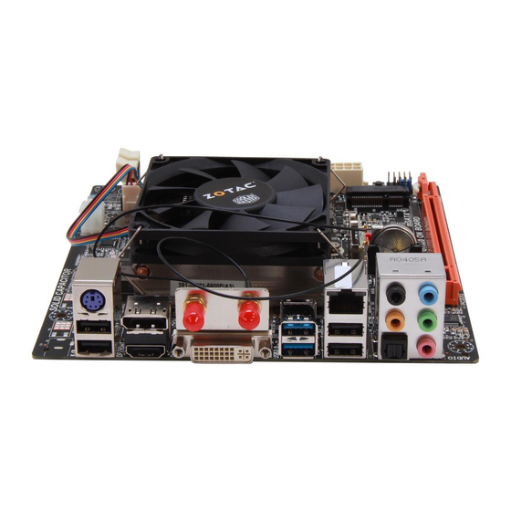
- Page 9 Intel D2700-ITX series Motherboard Figure 3. Backpanel Connectors For ATX version For DC-DC version 1. USB 2.0 Ports 2. HDMI Port 3. DVI Port 4. USB 3.0 Ports 5. Optical SPDIF Output 6. Port 2-Channel 4-Channel 6-Channel 8-Channel Blue Line-In Line-In Line-In Side Speaker Out...
- Page 10 Rear panel Note: 1. Users please note that the appearance of your WiFi antenna modules may not be exactly the same as those shown in this manual. 2. Users should install two WiFi antennas to the motherboard. 3. Users can bend or rotate the WiFi antennas to the best receiving direction according to the picture below.
-
Page 11: Hardware Installation
Intel D2700-ITX series Motherboard Hardware Installation This section will guide you through the installation of the motherboard. The topics covered in this section are: q Installing Memory Modules q Installing the Motherboard q Connecting Cables and Setting Switches Safety Instructions To reduce the risk of fire, electric shock, and injury, always follow basic safety precautions. -
Page 12: Installing Memory Modules
Hardware Installation Installing Memory Modules Your new motherboard has two 1.5V 204-pin slots for SO-DIMM DDR3 memory. These slots support 1 GB/2 GB DDR3 devices. There must be at least one memory bank populated to ensure normal operation. Refer to the following recommendations to install memory modules. DDRIII-1 DDRIII-2 Note that a memory module has a notch, so it can only fit in one direction. -
Page 13: Installing The Motherboard
Intel D2700-ITX series Motherboard Installing the Motherboard The sequence of installing the motherboard into the chassis depends on the chassis you are using and if you are replacing an existing motherboard or working with an empty chassis. Deter- mine if it would be easier to make all the connections prior to this step or to secure the mother- board and then make all the connections. -
Page 14: Installing An Msata Ssd Module (Optional)
Hardware Installation Installing an mSATA SSD module (optional) The motherboard supports one mSATA SSD via mini PCIe slot. Users please install the mSATA SSD module according to the following instructions. 1. Locate the Mini-PCIe slot of the motherboard, and insert an mSATA SSD into the slot at a 45 degree angle. -
Page 15: Connecting Cables And Setting Switches
Intel D2700-ITX series Motherboard Connecting Cables and Setting Switches This section takes you through all the connectors and switch settings necessary on the mother- board. This will include: q Power Connector v 24-pin ATX Power Connector-PW1 (for ATX version) v DC OUT Connector-CN12 (for DC-DC version) v 4-pin ATX_12V Power Connector-PW2 (for ATX version) q Internal Headers/Connectors v SPDIF-Out Header-CN5... -
Page 16: 24-Pin Atx Power Connector-Pw1 (For Atx Version)
Hardware Installation 24-pin ATX Power Connector-PW1 (for ATX version) PW1 is the main power supply connector. Make sure that the power supply cable and pins are properly aligned with the connector on the motherboard. Firmly plug the power supply cable into the connector and make sure it is secure. -
Page 17: Dc Out Connector-Cn12 (For Dc-Dc Version)
Intel D2700-ITX series Motherboard DC OUT Connector-CN12 (for DC-DC version) This motherboard can supply the power to SATA devices with a SATA power cable. Users can plug a SATA power cable (as picture 7) to the DC out connector (as picture 8). -
Page 18: Spdif-Out Header-Cn5
Hardware Installation SPDIF-Out Header-CN5 This header provides a SPDIF (Sony/Philips Digital Interface) output to digital multimedia device through coaxial connector. CN5 - Pin Definition COM Header-CN4 (optional) Signal CN4 - Pin Definition SPDIF-out Signal Signal Front Panel Header-FP1 The front panel header on this motherboard is one connector used to connect the following four cables : FP1-Pin Definition... -
Page 19: Usb Headers-Fp_U1
Intel D2700-ITX series Motherboard USB Headers-FP_U1 This motherboard contains four USB 2.0 and two USB 3.0 ports that are exposed on the rear panel of the chassis. The motherboard also contains one 10-pin internal USB 2.0 header onboard. Note: Secure the bracket to either the front or rear panel of your chassis (not all chassis are equipped with the front panel option). -
Page 20: Fan Connectors
Hardware Installation Fan Connectors There are two fan connectors on the motherboard, including system fan connector-SYSFAN1 and CPU fan connector-CPUFAN1. CPUFAN1 +12V Sense Control Control Sense +12V SATA1 SYSFAN1 SATA2 Serial-ATA (SATA) Connectors (SATA1/2) The Serial ATA connector is used to connect the Serial ATA device to the motherboard. These connectors support the thin Serial ATA cables for primary storage devices. -
Page 21: Expansion Slots
Intel D2700-ITX series Motherboard Expansion Slots The motherboard contains three expansion slots, twe Mini PCIe slots and one PCIe x16 slot. PCIE2 Mini PCI Express Slots-J1/J2 There are two Mini PCI Express slots. J1 supports one half-sized WiFi card. J2 supports one mSATA SSD. -
Page 22: Jumper Settings
Hardware Installation Jumper Settings This section explains how to configure the motherboard’s hardware. Before using your computer, make sure all jumpers and DRAM modules are set correctly. Refer to this section whenever in doubt. CMOS Clear Jumper-JP1 Selection 1-2* Normal* CMOS Clear Close Open... -
Page 23: Configuring The Bios
Intel D2700-ITX series Motherboard Configuring the BIOS This section discusses how to change the system settings through the BIOS Setup menus. Detailed descriptions of the BIOS parameters are also provided. Enter BIOS Setup The BIOS is the communication bridge between hardware and software. Correctly setting the BIOS parameters is critical to maintain optimal system performance. -
Page 24: X-Setting Menu
Configuring the BIOS q Memory Information Displays the auto-detected memory information. q HDD Information Displays the auto-detected HDD information. q System Date/Time Allows you to set the system date/time. X-Setting Menu The X-Setting menu items show the settings of voltage control. q DRAM voltage Control Use this item to set the DRAM voltage. -
Page 25: Advanced Menu
Intel D2700-ITX series Motherboard Advanced Menu The Advanced menu items allow you to change the setting for the CPU and other system devices. Press <enter> to display the configuration options: OnBoard Device Config The items in this menu allow you to set PCI Express port, HD Audio and so on. q PCI Express Port 0/1/2/3 Use this item to set the PCI Express Port. -
Page 26: Cpu Configuration
Configuring the BIOS CPU Configuration The items in this menu show the CPU-related information that the BIOS automatically detects. Press <enter> to display the configuration options: q Hyper-Threading Enable this function for Windows and Linux4 OS, (OS supports Hyper Threading Technology). -
Page 27: Intel Fast Flash Standby
Intel D2700-ITX series Motherboard Intel Fast Flash Standby The items in this menu allow you to change Intel Fast Flash standby features. Press <enter> to display the configuration options: q iFFS Support Use this item to enable or disable iFFS. q Entry on S3 RTC Wake Use this item to enable or disable entry on S3 RTC wake. -
Page 28: Power Management Menu
Power Management Menu The items in this menu allow you to control the system power management. Press <Enter> to display the configuration options: q Enable Hibernation Enable or disable system ability to hibernation (OS/S4 Sleep State). This option may be not effective with some OS. q ACPI Sleep State Select the highest ACPI sleep state, the system will enter when the SUSPEND button is pressed. -
Page 29: Boot Menu
Intel D2700-ITX series Motherboard Boot Menu The Boot menu items allow you to change the system boot options. Press <enter> to display the configuration options: q Setup Prompt Timeout Use this item to set number of seconds to wait for setup activation key. q Bootup NumLock State Use this item to select the keyboard NumLock state: [On] or [Off]. -
Page 30: Save & Exit Menu
Configuring the BIOS Configuring the BIOS q Full Screen Logo This option allows you to enable or disable the display of the full-screen logo when the system boots. Use the <Page Up> and <Page Down> keys to toggle between [Enable] and [Disable]. q GateA20 Active When set to [Upon Request], GA20 can be disabled using BIOS services. -
Page 31: Discard Changes And Exit
Intel D2700-ITX series Motherboard Discard Changes and Exit Select this option only if you do not want to save the changes that you have made to the setup program. If you made changes to fields other than system date, system time, and password, the BIOS asks for a confirmation before exiting. -
Page 32: Flash Update Procedure
Configuring the BIOS FLASH Update Procedure The program EFUDOS.exe is included in the driver dsk (X:\Utility\EFUDOS.exe). Please follow the recommended procedure to update the flash BIOS, as listed below. (X: your driver disk letter). 1. Create a DOS-bootable floppy diskette. Copy the new BIOS file (just obtained or downloaded) and the utility program EFUDOS.exe to the diskette. -
Page 33: Installing Drivers And Software
Intel D2700-ITX series Motherboard Installing Drivers and Software Note: 1. It is important to remember that before installing the driver disk that is shipped in the kit, you need to load your operating system. The motherboard supports Windows Vista 32 bit/64 bit and Windows 7 32bit/64bit. 2. - Page 34 Installing Drivers And Software 2. Left-click Intel Chipset Driver, begin loading...
- Page 35 Intel D2700-ITX series Motherboard 3. Left-click Realtek Sound Driver, begin loading...
- Page 36 Installing Drivers And Software Left-click Nvidia Graphics Driver, begin loading...
- Page 37 Intel D2700-ITX series Motherboard Left-click Realtek Network Driver, begin loading...
- Page 38 Installing Drivers And Software 6. Left-click Etron USB 3.0 Driver, begin loading...
- Page 39 Intel D2700-ITX series Motherboard 7. Left-click Intel Wireless Driver, begin loading...
- Page 40 Installing Drivers And Software...
- Page 41 Intel D2700-ITX series Motherboard At last, you can enter Computer Management that provides information about the hardware devices on this motherboard to check if the driver installation is complete.
-
Page 42: Realtek Hd Audio Driver Setup
Installing Drivers And Software Realtek HD Audio Driver Setup Getting Started After Realtek HD Audio Driver being installed (insert the driver dsk and follow the on-screen instructions), “Realtek HD Audio Manager” icon will show in System tray as below. Double click the icon and the control panel will appear: Double click to enable Realtek HD Audio Manager... -
Page 43: Environment Simulation
Intel D2700-ITX series Motherboard Environment Simulation You will be able to enjoy different sound experience by pulling down the arrow, totally 23 kinds of sound effect will be shown for selection. Realtek HD Audio Sound Manager also provides five popular settings “Sewer pipe”, “Bathroom”, “Arena”, “Stone Room”, and “Auditorium” for quick enjoyment. -
Page 44: Speakers
Installing Drivers And Software Speakers Realtek HD Audio Manager frees you from default speaker settings. Speakers includes four tabs: Speaker Configuration, Sound Effects, Room Correction and Default Format. Speaker Configuration In this tab, you can choose speaker configuration: Stereo, Quadraphonic, 5.1 Speaker or 7.1 Speaker using “Up/Down Arrow”. -
Page 45: Microphone
Intel D2700-ITX series Motherboard Microphone This page is designed to provide you better microphone/recording quality. Below picture indicates both “Noise Suppression” & “Acoustic Echo Cancellation” are both enabled. Noise Suppression If you feel that the background noise, especially the sound generated from the fan inside PC, is too loud? Try “Noise Suppression”, which allows you to cut off and suppress disturbing noise. -
Page 46: Line
Installing Drivers And Software Line In Realtek HD Audio Manager integrates “Volume Control” functions into the Line In page. This gives you the advantage to you to create your favorite sound effect in one single tool. Single click on the volume icon , the Recording/Playback Volume will be changed to the mute mode. -
Page 47: Device Adavanced Settings
Intel D2700-ITX series Motherboard Device Advanced Settings Click on “Device advanced settings” at the upper right corner of Realtek HD Audio Manager page, and you can set the playback device and recording device as below. Connector Settings Click on the icon on the main page of Realtek HD Audio Manager, and the Connector Settings dialog will display. -
Page 48: Information
Information Click on the icon at the lower right corner of Realtek HD Audio Manager page, the Realtek HD Audio information will display. Hardware / Software information of your audio system Language setting When “Audio” is chosen, this language setting would accommodate to OS language on your systems. - Page 49 Intel D2700-ITX series Motherboard 291-MA212-03...