Honeywell T7351 Product Data
Commercial programmable thermostat for single- or multi-stage conventional/heat pump systems
Hide thumbs
Also See for T7351:
- User manual (13 pages) ,
- Installation instructions manual (12 pages) ,
- Information (4 pages)
Table of Contents
Advertisement
Quick Links
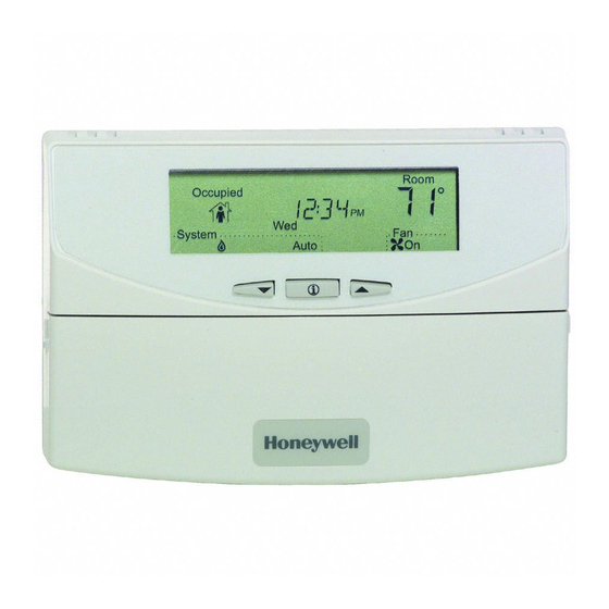
T7351 Commercial Programmable Thermostat
FOR SINGLE- OR MULTI-STAGE CONVENTIONAL/HEAT PUMP SYSTEMS
APPLICATION
The T7351 Commercial Programmable Thermostat controls
24 Vac commercial single zone heating, ventilating and air
conditioning (HVAC) equipment. The T7351 consists of a
thermostat and subbase. The thermostat includes the keypad
and display for 365-day programming. The subbase includes
equipment control connections. The subbase mounts on the
wall and the thermostat mounts to the subbase.
FEATURES
• Typically used in buildings (including: restaurants,
shopping malls, office buildings and banks) under
55,000 square feet.
• For single zone rooftop units, split systems, heat
pumps or hot/chilled water systems.
• 365-day programming.
• Two Occupied and two Not Occupied periods per day.
• Individual heat and cool setpoints available for
Occupied and Not Occupied periods.
• P+I+D control minimizes temperature fluctuations.
• Recovery ramp control automatically optimizes
equipment start times based on building load.
• Convenient overrides allow temporary setpoint
changes.
• Keypad multi-level lockout available with all models.
• Remote sensor capability for temperature (including
outdoor air and discharge air) and humidity sensors.
• Auxiliary subbase contact typically interface with a
Honeywell Economizer System (for total rooftop
control integration) or act as dehumidification output.
• Universal Versaguard Thermostat guards available.
Application ........................................................................
Features ...........................................................................
Specifications ...................................................................
Ordering Information ........................................................
Setting ..............................................................................
Installer Setup ..................................................................
Operation .......................................................................... 12
Troubleshooting Guide (Table 11) .................................... 17
Wiring Diagram (Figures 14 and 15) ................................ 19
PRODUCT DATA
Contents
1
1
2
2
6
7
63-2666-02
Advertisement
Table of Contents

Related Manuals for Honeywell T7351


Summary of Contents for Honeywell T7351
- Page 1 24 Vac commercial single zone heating, ventilating and air conditioning (HVAC) equipment. The T7351 consists of a • Auxiliary subbase contact typically interface with a thermostat and subbase. The thermostat includes the keypad Honeywell Economizer System (for total rooftop and display for 365-day programming.
-
Page 2: Application
If you have additional questions, need further information, or would like to comment on our products or services, please write or phone: 1. Your local Honeywell Automation and Control Products Sales Office (check white pages of your phone directory). 2. Honeywell Customer Care... - Page 3 6-9/16 (166) Contact your local waste management authority for instructions regarding recycling and the proper disposal Fig. 1. Thermostat and Subbase Dimensions of an old control. If you have questions, call Honeywell in inches (mm). Customer Care Center at 1-800-468-1502. Accessories:...
- Page 4 IMPORTANT Fig. 3. Four TR21 Sensors providing a Temperature To avoid electrical interference, which can cause Averaging Network for T7351 Thermostat. erratic performances, keep wiring runs as short as possible and do not run thermostat wires adjacent to the line voltage electrical distribution systems. Use...
- Page 5 3. Push excess wire back into the hole in the wall. 4. Plug the hole with nonflammable insulation to prevent drafts from affecting the thermostat. TR21 TR21 TR21 Table 3. T7351 Subbase for Three-stage Heat, Three-stage Cool Systems. Terminal TR21 TR21 TR21 Description 24 VAC Cooling transformer.
-
Page 6: Setting Temperature
T7351 COMMERCIAL PROGRAMMABLE THERMOSTAT SETTING Factory jumper between RC and RH for systems with one transformer. For changeover functional details, see Operation section. Using Thermostat Keys HC connection is not needed when using a TR23-H sensor. The thermostat keys are used to: •... -
Page 7: Setting
T7351 COMMERCIAL PROGRAMMABLE THERMOSTAT Table 4. T7351 Intelligent™ Fan ON control logic Call for Occupancy Heat/Cool Scheduled Motion Sensor Effective Period Signal Occupancy Notes Occupied No Sensor Wired Occupied Fan On Fan On Occupied Motion Sensed Occupied Fan On Fan On Effective Occupancy is Standby. -
Page 8: Installer Setup
T7351 COMMERCIAL PROGRAMMABLE THERMOSTAT a. If you want to save the new configuration, use the up NOTE: Installer Setup is automatically exited after five or down key to change NO to YES before minutes with no key pressed. Upon this automatic pressing Run Schedule. - Page 9 T7351 COMMERCIAL PROGRAMMABLE THERMOSTAT Table 5. Installer Setup. (Continued) Text Default Choices Notes OATSENS 0 0 - 1 Outdoor Air Sensor Selection 0: None 1: Remote Outdoor Air Sensor DATSENS 0 0 - 1 Discharge Air Sensor Selection 0: None...
- Page 10 T7351 COMMERCIAL PROGRAMMABLE THERMOSTAT Table 5. Installer Setup. (Continued) Text Default Choices Notes DAT HL YES or NO Discharge High Limit (Only displayed if Discharge Air Sensor is Selected) NO: None YES: Enabled DATHLSP 110° F 65° - 140° F Discharge High Temperature Limit (43°...
- Page 11 Third Thursday Fifth Monday Last Friday Second Monday Third Friday Fifth Tuesday Last Saturday Table 7. T7351 Key Function Summary. Grouping Button Definition Information Down Arrow Lowers setpoint, day, or time. When setting times or temperatures, hold key down to continuously decrease value.
-
Page 12: Special Functions
T7351 COMMERCIAL PROGRAMMABLE THERMOSTAT Table 7. T7351 Key Function Summary. (Continued) Grouping Button Definition Schedule Selects fan operation mode. Toggles between On and Auto. Run Schedule Resumes running schedule (cancels Temporary Occupied action, Holiday, and/or Temporary setpoint changes.) On: Continuous fan operation during occupied periods. During not occupied periods and in standby mode when no motion is sensed, fan cycles with call for heat or cool. -
Page 13: Operation
NOTE: In the items that follow, the term “error” refers to the difference between the measured space temperature All T7351 model thermostats contain at least four switching and the current actual space temperature setpoint: relays. In conventional applications, the relays control first stage cooling, first stage heating, fan, and auxiliary. - Page 14 T7351 COMMERCIAL PROGRAMMABLE THERMOSTAT — Recovery ramping applies between scheduled NOTE: The setpoint used during the cool recovery period is heat or cool setpoint changes from not occupied to similar to the heat mode in Fig. 10, except the slope standby and not occupied to occupied.
- Page 15 T7351 COMMERCIAL PROGRAMMABLE THERMOSTAT control. The potentiometer adjusts the minimum position of the The T7351 can take advantage of an economizer by closing economizer dampers, which provide a minimum amount of the auxiliary relay contacts to control the economizer minimum fresh air for ventilation.
- Page 16 NOTES: Dehumidifies by operating cooling during typical off time. The — 5% Hysteresis and a minimum timer prevent short T7351 maintains the proper setpoint by running the heat at the cycling of this output. same time. — Unlike Dehumid Hot Gas BP the relay remains energized during calls for multiple cooling stages.
-
Page 17: Troubleshooting Guide (Table 11)
Bad thermostat location. Relocate the thermostat. Display shows three dashes and a degree sign T7351 is set for the remote sensing and sensor is missing or (all systems shut down). circuit is either open or shorted. Temperature Upper or lower temperature limits were... - Page 18 T7351 COMMERCIAL PROGRAMMABLE THERMOSTAT Table 11. Troubleshooting Information. (Continued) Symptom Possible Cause Action Heat will not come No power to the thermostat. Check that X terminal is connected to the system transformer. Check for 24 Vac between X and RH terminals.
-
Page 19: Wiring Diagram (Figures 14 And 15)
T7351 COMMERCIAL PROGRAMMABLE THERMOSTAT WIRING DIAGRAM (FIGURES 14 AND 15) TR23-H REMOTE SENSOR OUTDOOR COMPRESSOR SENSOR CONTACTOR 2 10 11 12 DISCHARGE HEAT HEAT RELAY 3 RELAY 2 SENSOR SUBBASE W3/Y4 Y3 COMPRESSOR CONTACTOR 3 HEAT HUMIDITY MOTION RELAY 1... - Page 20 T7351 COMMERCIAL PROGRAMMABLE THERMOSTAT TR23-H REMOTE SENSOR OUTDOOR COMPRESSOR SENSOR CONTACTOR 2 10 11 12 AUX HEAT DISCHARGE STAGE 1 AIR SENSOR SUBBASE CHANGE- HUMIDITY MOTION OVER RELAY SENSOR SENSOR COMPRESSOR CONTACTOR 1 ECONOMIZER (HOT) (HOT) HEATING COOLING TRANSFORMER TRANSFORMER POWER SUPPLY.