Sign In
Upload
Download
Table of Contents
Contents
Add to my manuals
Delete from my manuals
Share
URL of this page:
HTML Link:
Bookmark this page
Add
Manual will be automatically added to "My Manuals"
Print this page
×
Bookmark added
×
Added to my manuals
Manuals
Brands
Lowrance Manuals
Sonar
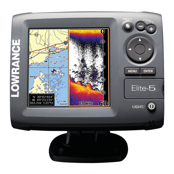
Elite 5
Operation manual
Lowrance Elite 5 Operation Manual
Hide thumbs
Also See for Elite 5
:
Installation instructions manual
(16 pages)
1
2
Table Of Contents
3
4
5
6
7
8
9
10
11
12
13
14
15
16
17
18
19
20
21
22
23
24
25
26
27
28
29
30
31
32
33
34
35
36
37
38
39
40
41
42
43
44
45
46
47
48
page
of
48
Go
/
48
Contents
Table of Contents
Bookmarks
Table of Contents
Table of Contents
Introduction
Unit Controls
Inserting Microsd Cards
Setup Wizard
Basic Operation
Selecting Pages
Page Menus
Working with Menus
Dialogs
Entering Text
Fishing Modes
Cursor
Goto Cursor
Advanced Mode
Standby Mode
Restore Defaults
Adjusting the Display
Pages
Steer Page
Sonar Page
Chart/Sonar Page
Chart Page
Overlay Data
Chart/Sonar Split
Using Your Sonar
Trackback
Sonar Menu
Sensitivity
Colorline/Grayscale
Depth Range
Frequency
Ping Speed (Advanced Mode Only)
Sonar Options
Fish ID
Stop Sonar
Using Your Chart
Chart Menu
Waypoints, Routes, Trails
Routes Screen
Trails Screen
Orientation
Settings
System
Saving Screenshots
Navigation
Chart
Sonar
Installation
Alarms
Index
Specifications
Advertisement
Quick Links
1
Unit Controls
2
Introduction
3
Inserting Microsd Cards
4
Basic Operation
5
Fishing Modes
6
Installation
Download this manual
Elite 5, Elite 4 & Mark 4
Installation & Operation
Operation manual
manual
SONAR COMBO COVER_.indd 1
9/13/2011 9:58:45 PM
Table of
Contents
Previous
Page
Next
Page
1
2
3
4
5
Advertisement
Table of Contents
Need help?
Do you have a question about the Elite 5 and is the answer not in the manual?
Ask a question
Questions and answers
Related Manuals for Lowrance Elite 5
Software Lowrance 5 Installation Instructions Manual
Gps module (16 pages)
Sonar Lowrance Elite 5m Operation Manual
Navico (36 pages)
Sonar Lowrance Elite 5 Sonar/GPS Installation & Operation Manual
Elite series (52 pages)
Sonar Lowrance Mark series DSI Operation Manual
(12 pages)
Sonar Lowrance Elite-7m Operation Manual
Navico (40 pages)
Sonar Lowrance Elite-7x Operation Manual
Navico (40 pages)
Sonar Lowrance Elite-5x Operation Manual
Sonar (40 pages)
Sonar Lowrance Mark-4 Operation Manual
(64 pages)
Sonar Lowrance Elite-5x HDI Operation Manual
(36 pages)
Sonar Lowrance Elite 5 DSI Operation Manual
Navico (47 pages)
Sonar Lowrance Elite 4 DSI Operation Manual
Navico (47 pages)
Sonar Lowrance Elite-3x Operation Manual
(13 pages)
Sonar Lowrance Elite-3x DSI Operation Manual
(12 pages)
Sonar Lowrance Elite 5X Operation Manual
Navico (28 pages)
Sonar Lowrance Mark-5x DSI Installation And Operation Manual
(36 pages)
Sonar Lowrance Elite 4 Operation Manual
(48 pages)
This manual is also suitable for:
Mark 4
Elite 4
Table of Contents
Save PDF
Print
Rename the bookmark
Delete bookmark?
Delete from my manuals?
Login
Sign In
OR
Sign in with Facebook
Sign in with Google
Upload manual
Upload from disk
Upload from URL


Need help?
Do you have a question about the Elite 5 and is the answer not in the manual?
Questions and answers