
Related Manuals for Siemens SIMATIC PANEL PC 877


Summary of Contents for Siemens SIMATIC PANEL PC 877
- Page 1 SIMATIC Industrial PC SIMATIC Panel PC 877 Operating Instructions Edition 07/2006 Industrial PC Panel PC 877 simatic DOCUMENTATION DOCUMENTATION...
- Page 3 Foreword Safety information Description SIMATIC Application planning Industrial PC Installation SIMATIC Panel PC 877 Connecting Integration into an Operating instructions automation system Commissioning Operation and configuration Operation Functions Maintenance and service Alarm, error and system messages Troubleshooting/FAQs Technical data Dimension drawings...
- Page 4 Trademarks All names identified by ® are registered trademarks of the Siemens AG. The remaining trademarks in this publication may be trademarks whose use by third parties for their own purposes could violate the rights of the owner.
-
Page 5: Table Of Contents
Connection and operator control components................6-1 Connecting the 100 V to 240 V AC power supply..............6-4 Connecting the 24 V DC power supply..................6-6 Connecting the equipotential bonding circuit ................6-7 SIMATIC Panel PC 877 Operating instructions, Release 07/2006, A5E00877780-01... - Page 6 Labelling function keys and softkeys ..................10-14 10.3.4 Using the integrated mouse ....................10-16 10.4 Device with touch screen ....................... 10-17 10.4.1 Using the touch screen ......................10-18 10.5 Disk drive..........................10-19 10.6 Transferring authorizations ....................10-20 SIMATIC Panel PC 877 Operating instructions, Release 07/2006, A5E00877780-01...
- Page 7 Backing up the hard disk......................12-46 Alarm, error and system messages ...................... 13-1 13.1 Boot error messages........................ 13-1 13.2 Introduction to the BIOS beep codes..................13-3 13.3 BIOS beep codes........................13-5 SIMATIC Panel PC 877 Operating instructions, Release 07/2006, A5E00877780-01...
- Page 8 17.6.6 Security menu ........................17-59 17.6.7 Power menu ........................... 17-61 17.6.8 Boot menu ..........................17-62 17.6.9 Version menu ......................... 17-64 17.6.10 Exit menu ..........................17-65 17.6.11 BIOS setup default settings....................17-66 SIMATIC Panel PC 877 Operating instructions, Release 07/2006, A5E00877780-01...
- Page 9 Dimensions for the mounting cut-out in mm ................4-10 Table 10-1 Keyboard codes ........................10-11 Table 13-1 Converting the beep codes in a Hex display ................13-3 Table 16-1 Panel PC 877 dimensions in mm..................... 16-2 SIMATIC Panel PC 877 Operating instructions, Release 07/2006, A5E00877780-01...
-
Page 10: Operating Instructions, Release 07/2006,
Table of contents SIMATIC Panel PC 877 viii Operating instructions, Release 07/2006, A5E00877780-01... -
Page 11: Foreword
Purpose of the manual These operating instructions contain all the information you need for commissioning and using the SIMATIC Panel PC 877. It is intended both for programming and testing personnel who commission the device and connect it with other units (automation systems, programming devices), as well as for service and maintenance personnel who install add-ons or carry out fault/error analyses. - Page 12 Trademarks All names labeled with ® symbol are registered trademarks of Siemens AG. Other names used in this documentation may be trademarks, the use of which by third parties for their own purposes could violate the rights of the owner.
-
Page 13: Safety Information
This device corresponds to the regulations of the EU low-voltage directive and the GPSG, verified by conformity with national and international standards (DIN EN, IEC) by a UL approval (cULuc). Please comply with all the information in these operating instructions when assembling the device. SIMATIC Panel PC 877 Operating instructions, Release 07/2006, A5E00877780-01... - Page 14 Unintentional operating situations High frequency radiation, e.g. from cell phones, can cause unintentional operating situations under some circumstances. Further information is available in the section "EMC requirements" of the "Technical data" chapter. SIMATIC Panel PC 877 Operating instructions, Release 07/2006, A5E00877780-01...
- Page 15 Repairs Only authorized personnel are permitted to repair the device. Warning Unauthorized opening of and improper repairs to the device may result in substantial damage to equipment or endanger the user. SIMATIC Panel PC 877 Operating instructions, Release 07/2006, A5E00877780-01...
-
Page 16: General Information
Optical drives are sensitive to vibration. Inadmissible vibration during operation may result in loss of data or damage to the drive or data medium. Before transporting the device, wait at least 20 seconds to allow the drive to stop completely. SIMATIC Panel PC 877 Operating instructions, Release 07/2006, A5E00877780-01... - Page 17 Tools & downloads Please check regularly if updates and hotfixes are available for download to your device. Downloads are available on the Internet at http://www.siemens.com/asis under "Support". Click on "Software Tools & Downloads" on "Overview Panel PCs" Using the global search function, you can then also search for any downloads you require.
- Page 18 50 minutes. Consider the following carefully: • Screen saver • Switch off the backlighting regularly • Permanent display of the customer application SIMATIC Panel PC 877 Operating instructions, Release 07/2006, A5E00877780-01...
-
Page 19: Description
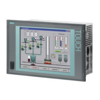
Computer unit Control unit Brief description The device is available with different control units which are distinguished by the size of the display and by the membrane keyboard or touch screen. SIMATIC Panel PC 877 Operating instructions, Release 07/2006, A5E00877780-01... - Page 20 • LEDs for power supply and temperature • Front-mounted USB 2.0 interface for connecting external I/O devices. All fronts are also available without USB interfaces accessible from the front. For additional information, refer to the Technical data. SIMATIC Panel PC 877 Operating instructions, Release 07/2006, A5E00877780-01...
-
Page 21: Technical Features
2x USB 2.0, high current Serial COM1 V.24, COM2 V.24 Parallel LPT1 Monitor 1 x DVI-I VGA monitors can be connected with a DVI/VGA adapter, to be purchased separately. Keyboard PS/2 Mouse PS/2 SIMATIC Panel PC 877 Operating instructions, Release 07/2006, A5E00877780-01... - Page 22 Preinstalled, also provided on the Restore DVD and Microsoft Recovery CD Windows 2000 Professional MUI* • Windows XP Professional MUI* • *MUI: Multi-lingual user interface; German, English, French, Italian, Spanish, Japanese, Korean, Chinese simplified and Chinese traditional SIMATIC Panel PC 877 Operating instructions, Release 07/2006, A5E00877780-01...
-
Page 23: Accessories
Remote Kit, 120/230 V AC, 20m 6AV7671-1EA12-0AA1 Remote Kit, 120/230 V AC, 30m 6AV7671-1EA13-0AA1 For further accessories, see Catalog or Siemens MALL 1) You can also find the print templates for the slide-in labels on the Internet http://www.siemens.com/asis Tools & Downloads>Downloads>Produkt Support>Industrie-PC , enter the entry ID 8782947. - Page 24 Description 3.3 Accessories SIMATIC Panel PC 877 Operating instructions, Release 07/2006, A5E00877780-01...
-
Page 25: Application Planning
• Rack installation Note In the following, the term "switchgear cabinet" also refers to rack, mounting rack, switchboard, operator panel and console. The term "device" represents the Panel PC and its variants. SIMATIC Panel PC 877 Operating instructions, Release 07/2006, A5E00877780-01... -
Page 26: Unpacking And Checking The Delivery
Warning Make sure that a damaged device is not installed nor put into operation. 8. Note the identification information as described in the chapter "Identification data of the device". SIMATIC Panel PC 877 Operating instructions, Release 07/2006, A5E00877780-01... -
Page 27: Device Identification Data
3. Enter the Ethernet address of the device: The Ethernet address is located in the "Main" menu of the BIOS setup, "Hardware Options > Ethernet Address." Identification Number Microsoft Windows Product Key COA SVP number Order number of the device Ethernet address SIMATIC Panel PC 877 Operating instructions, Release 07/2006, A5E00877780-01... -
Page 28: Mounting Positions And Fastening
UL approval as "open type" or "open equipment". For this reason, the device must be installed in a control cabinet or housing that complies with fire-proofing requirements SIMATIC Panel PC 877 Operating instructions, Release 07/2006, A5E00877780-01... - Page 29 UL-approval and compliance with the low-voltage directive (via EN 60950-1). In additional, the functionality of the device is no longer guaranteed. For additional information, refer to the dimension diagrams in the appendix. SIMATIC Panel PC 877 Operating instructions, Release 07/2006, A5E00877780-01...
-
Page 30: Permitted Mounting Positions
Certain mounting positions are approved for the equipment that comprises one control unit and one computer unit. Permitted mounting positions Vertical installation with deviations between +20° and -20° in the given directions is permissible. SIMATIC Panel PC 877 Operating instructions, Release 07/2006, A5E00877780-01... -
Page 31: Type Of Fixation
The computer unit is secured in the mounting cut-out either with clamps or screws. Select the type of fixation suitable to your requirements for the degree of protection (see Protection against dust and water Section SIMATIC Panel PC 877 Operating instructions, Release 07/2006, A5E00877780-01... -
Page 32: Protection Against Dust And Water
19" rack accessories are used. Note For screw fixing of the 19" touch panel front, a backing plate is available as an accessory. For further information, see "http://mall.ad.siemens.com/". SIMATIC Panel PC 877 Operating instructions, Release 07/2006, A5E00877780-01... -
Page 33: Mounting Cut-Out
120 in the seal area Setscrews Seal area Note Installed dimensions can be read from the dimension overview or they can be transferred to the cabinet from the mounting template supplied. SIMATIC Panel PC 877 Operating instructions, Release 07/2006, A5E00877780-01... -
Page 34: Table 4-1 Dimensions For The Mounting Cut-Out In Mm
Otherwise the mounting cut-out is useless. Complete the mounting cut-out in accordance with the dimensions. SIMATIC Panel PC 877 4-10 Operating instructions, Release 07/2006, A5E00877780-01... -
Page 35: Mounting Depth Of The Device
209 mm Touch panel with 19" 217 mm Note Additional mounting depth with optical drive The installation depth increases by 21 mm when an optical drive is installed in the device. SIMATIC Panel PC 877 4-11 Operating instructions, Release 07/2006, A5E00877780-01... -
Page 36: Emc Directive
ID 1064706 and the manual "PROFIBUS networks" with the article ID 1971286, which also applies to the installation of the device, is located on the "Documentation and Drivers" CD. SIMATIC Panel PC 877 4-12 Operating instructions, Release 07/2006, A5E00877780-01... -
Page 37: Installation
Secure the control unit in the mounting cut-out from behind with the clamps, as shown in the mounting cut-out in the dimensions. Tighten the setscrews to a torque of 0.4-0.5 Nm. SIMATIC Panel PC 877 Operating instructions, Release 07/2006, A5E00877780-01... - Page 38 1. The material strength at the mounting cut-out must be at least 2 mm. 2. The deviation from the plane in relation to the external dimensions for an installed HMI device is ≤ 0.5 mm SIMATIC Panel PC 877 Operating instructions, Release 07/2006, A5E00877780-01...
-
Page 39: Securing The Device With Screws
Deburr the holes from the front of the control unit Notice Risk of damage Ensure that no metal cuttings enter the device when the holes are drilled. Cover the device with film or when drilling, use removal by suction. SIMATIC Panel PC 877 Operating instructions, Release 07/2006, A5E00877780-01... -
Page 40: Rack Installation
Carefully drill the respective holes in the control unit at the designated location from the rear Working from the front, insert the device into the mounting cut-out Secure the control unit by inserting suitable screws through the holes and attaching nuts SIMATIC Panel PC 877 Operating instructions, Release 07/2006, A5E00877780-01... - Page 41 1. The material strength at the mounting cut-out must be at least 2 mm. 2. The deviation from the plane in relation to the external dimensions for an installed HMI device is ≤ 0.5 mm SIMATIC Panel PC 877 Operating instructions, Release 07/2006, A5E00877780-01...
- Page 42 Installation 5.2 Securing the device with screws SIMATIC Panel PC 877 Operating instructions, Release 07/2006, A5E00877780-01...
-
Page 43: Connecting
2 USB 2.0 connections high current (500 mA) Ethernet RJ45 connection for 10/100 Mbit/s (10) PROFIBUS/MPI MPI interface (RS485 electrically isolated) 9-pin Sub-D connector (11) COM 1 Serial interface 25-pin Sub-D connector SIMATIC Panel PC 877 Operating instructions, Release 07/2006, A5E00877780-01... - Page 44 On / Off switch The On / Off switch does not disconnect the device from mains. When the switch is in 0 position, the device is still connected to the auxiliary voltage. SIMATIC Panel PC 877 Operating instructions, Release 07/2006, A5E00877780-01...
- Page 45 • Peripherals are developed and marketed by individual vendors. The respective manufacturers offer support for the peripherals. Moreover, the terms of liability of the individual vendors or suppliers apply here. SIMATIC Panel PC 877 Operating instructions, Release 07/2006, A5E00877780-01...
-
Page 46: Connecting The 100 V To 240 V Ac Power Supply
If this cannot be guaranteed, in cabinet installation, for example, or the mains connector clamp is used, an easily accessible power switch must be built into the device. SIMATIC Panel PC 877 Operating instructions, Release 07/2006, A5E00877780-01... - Page 47 Steps for connecting the device to the 100 / 240 V AC power supply Switch off the AC power source Connect the power supply using the connector Power consumption The maximum AC power consumption is 360 W. SIMATIC Panel PC 877 Operating instructions, Release 07/2006, A5E00877780-01...
-
Page 48: Connecting The 24 V Dc Power Supply
Connect the 24 V DC power supply to the screw terminals: (1) +24 V DC (2) 0 V DC (3) protective ground conductor Power consumption The maximum DC power consumption is 265 W. SIMATIC Panel PC 877 Operating instructions, Release 07/2006, A5E00877780-01... -
Page 49: Connecting The Equipotential Bonding Circuit
Connect the equipotential bonding connection (M4 thread) (1) on the device (large surface, large-area contact) with the central grounding point of the control cabinet. The minimum permissible cross-section is 5 mm SIMATIC Panel PC 877 Operating instructions, Release 07/2006, A5E00877780-01... - Page 50 Connecting 6.4 Connecting the equipotential bonding circuit SIMATIC Panel PC 877 Operating instructions, Release 07/2006, A5E00877780-01...
-
Page 51: Integration Into An Automation System
SIMATIC S7. You require suitable software for this: STEP7, WinCC, WinCC flexible, WinAC, SIMATIC NET. Additional information For further information, refer to the catalog and to the online ordering system of Siemens A&D. Internet address: https://mall.ad.siemens.com SIMATIC Panel PC 877... -
Page 52: Device In A Simatic S7 Configuration
SIMATIC S7-CPU. To achieve baud rates over 1.5 Mbps, you require a 12 Mbps PROFIBUS cable with the order number 6ES7901-4BD00-0XA0. In the PROFIBUS DP MPI network, you can achieve data transmission rates of 9.6 Kbps to 12 Mbps. SIMATIC Panel PC 877 Operating instructions, Release 07/2006, A5E00877780-01... -
Page 53: Connecting An S7 Automation System
2. Insert the PROFIBUS cable in the MPI/DP socket. 3. Reconnect the device to the electrical power system. SIMATIC Panel PC 877 Operating instructions, Release 07/2006, A5E00877780-01... -
Page 54: Networking Via Industrial Ethernet
The interface is Plug and Play-ready and is automatically detected in Windows. Protocol settings are made in the Windows control panel. Notice A Class 5, CAT 5 Ethernet cable is required for 100 Mbit/s operation. SIMATIC Panel PC 877 Operating instructions, Release 07/2006, A5E00877780-01... -
Page 55: Commissioning
Allow the device to slowly adjust to room temperature before commissioning the device. Do not subject the device to direct heat radiation from devices such as heaters. Requirements • The equipotential bonding is connected. • The cables are correctly plugged in. SIMATIC Panel PC 877 Operating instructions, Release 07/2006, A5E00877780-01... -
Page 56: Switch On The Device
After connection to the power supply, the device performs a self test. During the self test, the message "Press F2 to enter SETUP" appears briefly. When the self-test is finished, the operating system will be loaded. SIMATIC Panel PC 877 Operating instructions, Release 07/2006, A5E00877780-01... -
Page 57: Setting Up The Microsoft Windows Operating System
4. If this PC name is already in use as you attempt to connect the device to a network: Enter a new PC name for identification. The operating system will restart automatically. The system settings are updated. The desktop is set up. The setup of the operating system is complete. SIMATIC Panel PC 877 Operating instructions, Release 07/2006, A5E00877780-01... -
Page 58: Installing Applications And Drivers
Panel Wizard, selection of the panel type When selecting the Touch Panel, proceed according to the section Set Touchscreen. To select the Key Panel, proceed as described in the section Set key fron. SIMATIC Panel PC 877 Operating instructions, Release 07/2006, A5E00877780-01... - Page 59 Windows startup. An external keyboard is then not necessary. If you deactivate the check-box, the screen keyboard does not appear. It will, however, be installed. SIMATIC Panel PC 877 Operating instructions, Release 07/2006, A5E00877780-01...
- Page 60 4. New hardware, the touch controller, is found. In order to start the touch calibration, click on "OK". Carry out the following steps carefully: Figure 8-4 Start touch screen calibration 5. Briefly touch the touch screen at every cross hair. Continue from Point 7. SIMATIC Panel PC 877 Operating instructions, Release 07/2006, A5E00877780-01...
-
Page 61: Operation And Configuration
8. No administrator password is assigned in the factory state. When the logon dialog appears the next time the device starts up, therefore, leave the field empty and close the dialog with the "OK" button. Notice Then configure an administrator password for security. SIMATIC Panel PC 877 Operating instructions, Release 07/2006, A5E00877780-01... - Page 62 After starting up your device, find out more about the particulars of the operating system in the chapter "Commissioning" in the section, "Microsoft Windows operating systems". Further information is available in the chapter "Service and maintenance" under the section, "Installing software." SIMATIC Panel PC 877 Operating instructions, Release 07/2006, A5E00877780-01...
-
Page 63: Bios Settings
A requirement for activation is that "USB BOOT" <enable> has been selected in the BIOS. Note To edit the BIOS on the operator device with a touchscreen, connect a USB keyboard or an external PS/2 keyboard. SIMATIC Panel PC 877 Operating instructions, Release 07/2006, A5E00877780-01... -
Page 64: Microsoft Windows Operating System
Windows XP Professional is only approved as of Service Pack 2. The operating system is provided with the Windows function modes "Hibernate" and "Standby" deactivated when shutting down the operating system and with "Fast User Switch" (Windows XP Professional) deactivated. SIMATIC Panel PC 877 8-10 Operating instructions, Release 07/2006, A5E00877780-01... -
Page 65: Windows 2000 Professional
Updates will then no longer be performed automatically on the device via the Internet. Notice When the check-box is activated, updates will be installed automatically on the device via the Internet even when they have not been released by Siemens AG. SIMATIC Panel PC 877 8-11... -
Page 66: Windows Xp Professional
Updates will then no longer be performed automatically on the device via the Internet. Notice When the check-box is activated, updates will be installed automatically on the device via the Internet even when they have not been released by Siemens AG. SIMATIC Panel PC 877 8-12... -
Page 67: Usb
Before removing an intelligent USB device, deactivate the device in the operating system using the dialog "Unplug or Eject Hardware". For additional information, refer to the documentation for the operating system. SIMATIC Panel PC 877 8-13 Operating instructions, Release 07/2006, A5E00877780-01... - Page 68 Commissioning 8.7 USB SIMATIC Panel PC 877 8-14 Operating instructions, Release 07/2006, A5E00877780-01...
-
Page 69: Operation And Configuration
"Operation and configuration" chapter in the section, "Additional drivers and applications." • The proper ambient and environmental conditions according to the specifications for the device and the connected I/O modules have been observed. SIMATIC Panel PC 877 Operating instructions, Release 07/2006, A5E00877780-01... - Page 70 "Press <F2> to enter SETUP" appears briefly. When the self-test is finished, the operating system will be loaded and the desktop will be displayed. The booting process has been completed successfully. SIMATIC Panel PC 877 Operating instructions, Release 07/2006, A5E00877780-01...
-
Page 71: Logging On To The Operating System Via The Onscreen Keyboard (Osk)
A screen keyboard appears for devices with touch screen panels. You can enter the administrator password directly on the touch screen using the screen keyboard or using the mouse. For additional information, refer to the Microsoft help on screen keyboards. SIMATIC Panel PC 877 Operating instructions, Release 07/2006, A5E00877780-01... -
Page 72: Switching Off The Device
In the case of the direct key module, make sure the keys of the membrane keyboard that are configured as direct control keys remain operable until the voltage of the entire device has been switched off. SIMATIC Panel PC 877 Operating instructions, Release 07/2006, A5E00877780-01... -
Page 73: Additional Drivers And Applications
The supplied drivers and applications have been system-tested and are approved for this device. No warranty can be provided for other software. Press the "Help" button to obtain information concerning the buttons of a dialog. SIMATIC Panel PC 877 Operating instructions, Release 07/2006, A5E00877780-01... -
Page 74: Calibrating The Touch Screen, Updd
If the touch screen does not react as expected when touched, repeat the calibration. To do this, first activate the 25 point calibration and then calibrate the touch screen. Figure 9-1 25-point calibration Note For further information press the "Help" button. SIMATIC Panel PC 877 Operating instructions, Release 07/2006, A5E00877780-01... - Page 75 Do not touch the screen in the following situations: — When the device is booting until the boot process is completed — When plugging or unplugging USB components — While Scandisk is running SIMATIC Panel PC 877 Operating instructions, Release 07/2006, A5E00877780-01...
-
Page 76: Enable/Disable Touch Functionality
"Advanced" tab. In the "Advanced" tab, deactivate the "Enabled" option and load the settings by clicking the "Apply" button. The touch screen is now deactivated. SIMATIC Panel PC 877 Operating instructions, Release 07/2006, A5E00877780-01... - Page 77 "Show inactive PnP devices". Then select the "Advanced" tab again. In the "Advanced" tab, deactivate the "Enabled" option and load the settings by clicking the "Apply" button. The touch functionality is now activated again. SIMATIC Panel PC 877 Operating instructions, Release 07/2006, A5E00877780-01...
-
Page 78: Windows Security Center (Windows Xp Professional Only)
Activates and deactivates the following functions on the device: Function Default setting Firewall Automatic updates Virus protection Alarms The default settings can be activated and deactivated. Figure 9-2 Windows Security Center SIMATIC Panel PC 877 9-10 Operating instructions, Release 07/2006, A5E00877780-01... - Page 79 Click on "Change the way Security Center alerts me" to switch off security alarms upon switching on the device. The "Alert Settings" dialog appears. Deactivate the desired alarms. Figure 9-3 "Alert Settings" Dialog SIMATIC Panel PC 877 9-11 Operating instructions, Release 07/2006, A5E00877780-01...
-
Page 80: Keytools (For Key Panel Devices Only)
F11 to F20 and S1 to S16 are used or if own key code tables are used. SIMATIC Panel PC 877 9-12 Operating instructions, Release 07/2006, A5E00877780-01... -
Page 81: Screen Keyboard (For Touch Panel Device Only)
Calling up TouchInput Call up the "TouchInput" application on the desktop. The screen keyboard is displayed. Key for selecting the keyboard layouts for specific countries: German, English, Italian, Spanish, French SIMATIC Panel PC 877 9-13 Operating instructions, Release 07/2006, A5E00877780-01... -
Page 82: Setbrightness
Operation and configuration 9.2 Additional Drivers and Applications 9.2.7 Setbrightness Start "Set brightness" symbol on the desktop. Function The intensity of the backlighting is adjusted using "Set brightness." Figure 9-4 Setbrightness SIMATIC Panel PC 877 9-14 Operating instructions, Release 07/2006, A5E00877780-01... -
Page 83: Checklanguageid
"CheckLanguageID" displays the currently installed languages. Figure 9-5 CheckLanguageID • SystemDefaultLangID: System language • UserDefaultLangID: Standard language • UserDefaultUILangID: User interface language Notice All three languages displayed should have the same ID assigned. SIMATIC Panel PC 877 9-15 Operating instructions, Release 07/2006, A5E00877780-01... -
Page 84: Multilingual Settings For The Operating System
Default language of your Windows XP Professional MUI installation is English and a US keyboard layout. You can change the language in the Control Panel. Select: SIMATIC Panel PC 877 9-16 Operating instructions, Release 07/2006, A5E00877780-01... - Page 85 Languages tab,Language used in menus and dialogs field. For the Date, Time, Language and Regional Options set the default as non-Unicode programs under Advanced in addition to the language for menus and dialogs. SIMATIC Panel PC 877 9-17 Operating instructions, Release 07/2006, A5E00877780-01...
-
Page 86: Dvd Rom/Cd Rw
When backing up an image, the data should be restored to the hard disk and the system should be rebooted from the hard disk. SIMATIC Panel PC 877 9-18 Operating instructions, Release 07/2006, A5E00877780-01... -
Page 87: Usb Keyboard Controller
• Control of the key LEDs The USB keyboard controller must be installed before this function can be used. For installation instructions, see the description on the "Documentation and Drivers" CD. SIMATIC Panel PC 877 9-19 Operating instructions, Release 07/2006, A5E00877780-01... - Page 88 Operation and configuration 9.2 Additional Drivers and Applications SIMATIC Panel PC 877 9-20 Operating instructions, Release 07/2006, A5E00877780-01...
-
Page 89: Operation
• LED "POWER" green: Active voltage • LED "TEMP" orange: The temperature threshold has been exceeded; the maximum value is preset and cannot be changed. Refer to the "Functions" chapter for more information. SIMATIC Panel PC 877 10-1 Operating instructions, Release 07/2006, A5E00877780-01... -
Page 90: General Control Elements
The button signal triggers a hardware reset. The PC performs a restart (cold start). Caution Data may be lost when the PC performs a hardware reset! SIMATIC Panel PC 877 10-2 Operating instructions, Release 07/2006, A5E00877780-01... -
Page 91: Device With Key Panel
Alphanumeric keys, numeric keys, cursor keys and control keys Integrated mouse Function keys, softkeys (to the left and right of the display) USB interface (in some device variants, the front USB interface cannot be used) SIMATIC Panel PC 877 10-3 Operating instructions, Release 07/2006, A5E00877780-01... -
Page 92: Using The Keyboard
Function keys with LEDs, taking the 15" control unit as an example Softkeys The softkeys are arranged on the left and the right of the display. Figure 10-3 Softkeys with LEDs, taking the 15" control unit as an example SIMATIC Panel PC 877 10-4 Operating instructions, Release 07/2006, A5E00877780-01... -
Page 93: Control Keys
Application-specific functions and special key codes, compare keyboard table in the appendix Application-specific functions and special key codes, compare keyboard table in the appendix Toggling between lower-case letters and upper-case letters Function key (10) Call Help (11) Tabulator (12) Backspace SIMATIC Panel PC 877 10-5 Operating instructions, Release 07/2006, A5E00877780-01... - Page 94 3. To enter lower case letters, release the <Shift> key. 4. You can, however, also activate the Caps Lock function using the F and Shift keys. The LED on the Shift key is then also lit. SIMATIC Panel PC 877 10-6 Operating instructions, Release 07/2006, A5E00877780-01...
- Page 95 2. Activate the desired alphanumeric or numeric key at the same time. The displayed special character, arithmetic sign or signs will be entered. 3. To enter the signs of the pre-defined assignment again, release the <FN> key. SIMATIC Panel PC 877 10-7 Operating instructions, Release 07/2006, A5E00877780-01...
- Page 96 PC keyboard. Figure 10-7 Cursor keys <Left> key <Up> key <Right> key <Down> key Position 1 key (Home) <Page up> key <Page down> key SIMATIC Panel PC 877 10-8 Operating instructions, Release 07/2006, A5E00877780-01...
- Page 97 F13 to S16 are used or if own key code tables are used. Notice Risk of damage Activating a key using a hard or pointed object, e.g. a screwdriver, reduces the life of the key or can damage it. SIMATIC Panel PC 877 10-9 Operating instructions, Release 07/2006, A5E00877780-01...
-
Page 98: Using The Direct Control Key Module
4 screws on a wall / front panel / control panel. Detailed mounting instructions are included with every direct control key module on paper and with every Panel PC 877. SIMATIC Panel PC 877 10-10 Operating instructions, Release 07/2006, A5E00877780-01... - Page 99 S5 - S16 CTRL+F1 - CTRL+F12 This default setting for additional function keys corresponds to the specifications required for using the keys (for example, from the HMI software package SIMATIC WinCC flexible). SIMATIC Panel PC 877 10-11 Operating instructions, Release 07/2006, A5E00877780-01...
- Page 100 The individual key fields can be clicked to open a configuration form for the respective key. In the example, the form for standard assignment of the F13 key is shown: Figure 10-9 Standard assignment of the F13 key SIMATIC Panel PC 877 10-12 Operating instructions, Release 07/2006, A5E00877780-01...
- Page 101 For further information about using the tool, visit the Internet page http://www.siemens.com/asis. Search here under "Download" using the term "Keypad". The self-unpacking file F_KEY_Total.exe contains extensive information (description in English and German, examples) on using the additional function keys of the Panel PC 877.
-
Page 102: Labelling Function Keys And Softkeys
3 "Description". Warning Labeling Label the function keys and softkeys to conform with the project. Labeling without reference to a project leads to incorrect operations on the system to be observed. SIMATIC Panel PC 877 10-14 Operating instructions, Release 07/2006, A5E00877780-01... - Page 103 Figure 10-10 Rear side of the control unit with connections and slots for the labeling strips for the example of a 12" touch panel front. Slots for long labeling strips, vertical keypads Slots for short labeling strips, horizontal keypads Slots for labeling strips, horizontal keypads SIMATIC Panel PC 877 10-15 Operating instructions, Release 07/2006, A5E00877780-01...
-
Page 104: Using The Integrated Mouse
The amount of pressure determines the speed of the cursor. Alternatively to using the integrated mouse you can also connect an external mouse to the front USB port. Figure 10-11 Integrated mouse SIMATIC Panel PC 877 10-16 Operating instructions, Release 07/2006, A5E00877780-01... -
Page 105: Device With Touch Screen
The following figure is only an example using the front view of the 15" variant. Figure 10-12 Example of a 15" touch screen front Display with touch screen USB interface (in some device variants, the front USB interface is not accessible) SIMATIC Panel PC 877 10-17 Operating instructions, Release 07/2006, A5E00877780-01... -
Page 106: Using The Touch Screen
Touching the touch screen with hard or pointed objects can damage the screen and thus impair its functionality. Only operate the touch screen with your fingers (even with gloves) or approved touch pens. SIMATIC Panel PC 877 10-18 Operating instructions, Release 07/2006, A5E00877780-01... -
Page 107: Disk Drive
Double sided double density Double sided high density 720 KB 1.44 MB, 135 TPI Caution Data loss! Do not press the ejection button when the green access LED of the drive is lit. SIMATIC Panel PC 877 10-19 Operating instructions, Release 07/2006, A5E00877780-01... -
Page 108: Transferring Authorizations
Operation 10.6 Transferring authorizations 10.6 Transferring authorizations 10.6 Authorizations of HMI software are provided on diskette. Transfer these, if required, from the built-in diskette drive. SIMATIC Panel PC 877 10-20 Operating instructions, Release 07/2006, A5E00877780-01... -
Page 109: Functions
DiagMonitor software can be ordered as an accessory with a separate order number. The description of the driver and the SOM program are available on the "Documentation and Drivers" CD. SIMATIC Panel PC 877 11-1 Operating instructions, Release 07/2006, A5E00877780-01... -
Page 110: Safecard On Motherboard (Som)
Your device is equipped with three temperature sensors, which are automatically detected by the application. Figure 11-1 Safecard On Motherboard with three temperature sensors SIMATIC Panel PC 877 11-2 Operating instructions, Release 07/2006, A5E00877780-01... - Page 111 The description of the drivers and SOM software for Windows is available on the "Documentation and Drivers" CD under Drivers/Tools >Tools>PPC877. From the CD, run Install.bat and follow the instructions on your screen. SIMATIC Panel PC 877 11-3 Operating instructions, Release 07/2006, A5E00877780-01...
-
Page 112: Temperature Monitoring
• Error acknowledgement in the SOM program (manually by means of the broom icon) • Restart of the device Notice When an error occurs, the "TEMP" LED also illuminates with the status indicators. SIMATIC Panel PC 877 11-4 Operating instructions, Release 07/2006, A5E00877780-01... -
Page 113: Watchdog (Wd)
The TWD are adjustable in increments of one second in a range from 3 to 255 seconds. Note If the watchdog time is changed after the watchdog was enabled (i.e., while the watchdog is running), the watchdog is retriggered! SIMATIC Panel PC 877 11-5 Operating instructions, Release 07/2006, A5E00877780-01... -
Page 114: Fan Monitoring
The temperature error is retained until the cause of the fan failure has been rectified and the error is reset in one of the following ways: • Acknowledgement of the error message by means of the SOM program • Restart of the device SIMATIC Panel PC 877 11-6 Operating instructions, Release 07/2006, A5E00877780-01... -
Page 115: Maintenance And Service
Use dish soap or foaming screen cleaner only as cleaning agents. Caution Do not clean the device with aggresive solvents or scrubbing agents or with pressurized air or steam cleaner. SIMATIC Panel PC 877 12-1 Operating instructions, Release 07/2006, A5E00877780-01... - Page 116 Caution Adhere to the information regarding chemical resistance of the panel front. Please go to http://www.siemens.com/asis under "Tools & Downloads" for more information. Enter the article ID 16532108 as the search term. The available articles are displayed. Procedure for cleaning the device 1.
-
Page 117: Replacement Parts
Lithium battery A5E00331143 *) For more information, please refer to the chapter "Description." Use only Siemens spare parts or spare parts released by Siemens, otherwise the warranty, CE declaration of conformity and UL approval will be invalidated. SIMATIC Panel PC 877... -
Page 118: Separating The Control Unit From The Computer Unit
Figure 12-1 Separating the control unit from the computer unit 4. Swing the computer unit (1) away. The connectors on the back of the control unit (3) are now accessible. SIMATIC Panel PC 877 12-4 Operating instructions, Release 07/2006, A5E00877780-01... - Page 119 Figure 12-2 Other interfaces on the computer unit Display cable K2 and display cable K3 USB cable IO/USB cable K1 *) Only for 19" touch panel fronts. SIMATIC Panel PC 877 12-5 Operating instructions, Release 07/2006, A5E00877780-01...
- Page 120 Figure 12-3 Separate the control unit from the computer unit, example regarding folding cables Position Bend dimension 4.5 cm 4 cm SIMATIC Panel PC 877 12-6 Operating instructions, Release 07/2006, A5E00877780-01...
-
Page 121: Installing And Removing Hardware Components
• Before you open the device, always disconnect the power plug. • Install only system upgrades designated for this computer and released by SIEMENS. All technical data and licenses apply only to upgrades approved by SIEMENS. Installation of unsuitable components violates the regulations for UL approval and EMC. -
Page 122: Open The Device
(ESD) directives for handling components which are sensitive to electrostatic charge. Tools You can perform all installation tasks on the device using Torx T6, Torx T10, and Torx T20 screwdrivers and a Philips screwdriver. Preparation Disconnect the device from mains. SIMATIC Panel PC 877 12-8 Operating instructions, Release 07/2006, A5E00877780-01... - Page 123 Maintenance and service 12.4 Installing and removing hardware components Open the device Steps for opening the device Remove the five screws (1). Swing the lid to the front and remove it. SIMATIC Panel PC 877 12-9 Operating instructions, Release 07/2006, A5E00877780-01...
-
Page 124: Installing And Removing Memory Modules
The electronic components on the PCBS are highly sensitive to electrostatic discharge. It is therefore vital to take precautionary measures when handling these components. Refer to the directives for handling electrostatic sensitive components. For more information, please refer to the section "ESD directives". SIMATIC Panel PC 877 12-10 Operating instructions, Release 07/2006, A5E00877780-01... - Page 125 Close the device Displaying the memory configuration A new memory module is automatically detected. The allocation of the ”base memory and extended memory” is displayed when you switch on the device. SIMATIC Panel PC 877 12-11 Operating instructions, Release 07/2006, A5E00877780-01...
-
Page 126: Installing Pci / At Cards
Note about long PCI modules Before long PCI modules can be inserted into the guide rails, they must be fitted with an extender (this should be supplied with the long PCI board). SIMATIC Panel PC 877 12-12 Operating instructions, Release 07/2006, A5E00877780-01... -
Page 127: Installing / Removing Expansion Modules
Insert the expansion module (4) into the relevant slot. Install the module holding- down device and insert the slider. Secure the steel slot cover (3) of the expansion module. Close the device. SIMATIC Panel PC 877 12-13 Operating instructions, Release 07/2006, A5E00877780-01... - Page 128 Use a knife to notch the slider at the upper edge of the bracket and then break this section off. Cut off the residual element using a sharp side cutter. SIMATIC Panel PC 877 12-14 Operating instructions, Release 07/2006, A5E00877780-01...
-
Page 129: Exchanging The Raid Controller Pci Card
The RAID system uses the following controllers: • System with SATA drives: Promise Fast Track TX2300 Principle The RAID controller PCI card is installed in PCI slot 5 of the bus module. SIMATIC Panel PC 877 12-15 Operating instructions, Release 07/2006, A5E00877780-01... -
Page 130: Disk Drives
Mounting slot for DVD-ROM or DVD-ROM/CD-RW drive Hard disk drive bay for one 3.5" drive Pos Description Hard disk drive bay for one 3.5" drive Mounting slot for a 3.5" hard disk drive bay SIMATIC Panel PC 877 12-16 Operating instructions, Release 07/2006, A5E00877780-01... - Page 131 Drive bays for two 2.5" hard disks Pos Description Hard disk drive bay for 2.5" hard disks Two mounting slots for 2.5" hard disks Drive bay for floppy disk drive Pos Description Floppy disk drive SIMATIC Panel PC 877 12-17 Operating instructions, Release 07/2006, A5E00877780-01...
-
Page 132: Installing / Removing A Drive Bay
Disconnect the device from mains and unplug all cables. Remove the hard disk bay Steps for removing the drive bay Remove the four screws (1) Remove the hard disk bay and place it onto the device SIMATIC Panel PC 877 12-18 Operating instructions, Release 07/2006, A5E00877780-01... - Page 133 Removing drive bays for floppy disk drives Steps for removing the floppy disk drive bay Remove the four screws (1) Remove the hard drive bay and place it onto the device. SIMATIC Panel PC 877 12-19 Operating instructions, Release 07/2006, A5E00877780-01...
- Page 134 (2). Remove the screw (3) and open the bracket. Disconnect the connecting cable for the optical drive. Remove the three screws (1) Lift the drive bay out SIMATIC Panel PC 877 12-20 Operating instructions, Release 07/2006, A5E00877780-01...
-
Page 135: Removing And Installing An Optical Drive
1. Unscrew the 4 screws (1) holding the drive and slide the drive out. Figure 12-4 Installing and removing the optical drive 1. If you need to completely remove the drive, remove drive connectors (1) and (2) from the device. SIMATIC Panel PC 877 12-21 Operating instructions, Release 07/2006, A5E00877780-01... - Page 136 12.4 Installing and removing hardware components Figure 12-5 Drive connectors 2. Loosen the 2 screws (1) of the drive housing. Figure 12-6 Drive with housing 3. Flip up the housing cover (1) 90°. SIMATIC Panel PC 877 12-22 Operating instructions, Release 07/2006, A5E00877780-01...
- Page 137 Loose spacer bolts are located between the housing and the board. When loosening the board, hold the spacer bolts in place. 8. Remove the board (6). Reverse the procedure to install the drive. SIMATIC Panel PC 877 12-23 Operating instructions, Release 07/2006, A5E00877780-01...
-
Page 138: Removing And Installing A 3.5" Hard Disk
Removed hard disk 3. Loosen the 4 screws that secure the hard disk to the drive bay. 4. Remove the drive from the bracket. Reverse the procedure to install the drive. SIMATIC Panel PC 877 12-24 Operating instructions, Release 07/2006, A5E00877780-01... -
Page 139: Replacing The Backup Battery
100° C, dispose as regulated and protected against direct exposure to sunlight, humidity and dewing. Disposal Caution Batteries must be disposed of in accordance with local regulations. SIMATIC Panel PC 877 12-25 Operating instructions, Release 07/2006, A5E00877780-01... - Page 140 Close the device. Reconfiguring the BIOS Setup When a battery is exchanged, the configuration data of the device are lost and must be reentered in the BIOS setup. SIMATIC Panel PC 877 12-26 Operating instructions, Release 07/2006, A5E00877780-01...
-
Page 141: Removing/Installing The Power Supply
Remove the hard disk drive bay. Remove the 6 screws (1) and the cover of the power supply module. Disconnect the power supply cables of all drives. Remove the 3 fastening screws (1) (Torx T10). SIMATIC Panel PC 877 12-27 Operating instructions, Release 07/2006, A5E00877780-01... - Page 142 Pull the power supply module out to the front. Also remove the four screws holding the steel bracket of the PS and take it off. These are special screws with imperial dimensions (6-32x3/16''-St-G3E). SIMATIC Panel PC 877 12-28 Operating instructions, Release 07/2006, A5E00877780-01...
-
Page 143: Installing Software
Documentation and Drivers CD: Contains the documentation and the hardware drivers. Restore DVD: Contains a hard disk image file with the original software (operating system with installed hardware drivers). SIMATIC Panel PC 877 12-29 Operating instructions, Release 07/2006, A5E00877780-01... -
Page 144: Setting Up The Partitions For Windows Operating Systems
1. Boot from the Recovery CD and then follow the screen instructions until the Recovery functions window is displayed. 2. Start the DiskPart program in the "Siemens SIMATIC Recovery“ window and enter the following commands in the displayed command interface: list disk Displays all available hard disks. - Page 145 NTFS is the factory setting for all Windows operating systems. Example for a master hard disk on the IDE bus: format C:/FS:NTFS Note Parameter overview format /? shows all parameters of the command. SIMATIC Panel PC 877 12-31 Operating instructions, Release 07/2006, A5E00877780-01...
-
Page 146: Compatibility Of The Restore Dvd
Restore DVD matches that of the device. You can find the order number of the device on the rating plate. Do not use the supplied images for any other device. The chipsets and drivers differ. SIMATIC Panel PC 877 12-32 Operating instructions, Release 07/2006, A5E00877780-01... -
Page 147: Restoring The Factory State Of The Software Using The Restore Dvd
3. Select the optical drive with the cursor keys. 4. Now follow the instructions on the screen. Caution All existing data, programs, user settings and authorizations or License Keyswill bedeleted from the hard disk and are therefore lost. SIMATIC Panel PC 877 12-33 Operating instructions, Release 07/2006, A5E00877780-01... - Page 148 All existing data, programs, user settings and authorizations or License Keyswill bedeleted from the hard disk and are therefore lost. For information on the functions, refer to the README.TXT file on the Restore DVD. SIMATIC Panel PC 877 12-34 Operating instructions, Release 07/2006, A5E00877780-01...
-
Page 149: Installing Microsoft Windows Operating Systems
— The device has features that a standard PC does not, for example, a touch screen and front panel function keys. — Siemens AG can only guarantee the availability of these features for operating systems that have been released. — Siemens AG only provides support within a strictly defined framework. -
Page 150: Booting From The Recovery Cd
”Press <F2> to enter Setup or <ESC> to show Boot Menu" appears, press the ESC key. After initialization, a "Boot Menu" is displayed. 2. Select the optical drive with the cursor keys. 3. Please follow the on-screen instructions until the "Siemens SIMATIC Recovery" window appears. SIMATIC Panel PC 877... -
Page 151: Installing The Microsoft Windows Operating System (Not For Raid)
3. Please follow the on-screen instructions until the "Siemens SIMATIC Recovery" window appears. 4. After copying the Windows installation files, return to the Siemens SIMATIC Recovery main menu (click "Back"). 5. Select "Start command prompt" in the Recovery functions window. -
Page 152: Installing The Microsoft Windows Operating System (For Raid)
9. Set the appropriate drive letter in folder I386 and start "Winnt32.bat" from this folder Note After copying the Windows installation files, return to the "SIEMENS Simatic Recovery" main menu. 10. Close the Siemens SIMATIC Recovery window with the "Finish" button 11. -
Page 153: Installing Individual Drivers
Procedure 1. Start "Start.exe" in the root directory of the CD. 2. Follow the instructions displayed on the screen. Note For further information on reinstalling the drivers, go to http://www.siemens.com/asis, under "Support". SIMATIC Panel PC 877 12-39 Operating instructions, Release 07/2006, A5E00877780-01... -
Page 154: Operation Of Two Hard Disks
IDE bus and change the jumper settings on the drive as required (master setting, see the label on the drive.) SIMATIC Panel PC 877 12-40 Operating instructions, Release 07/2006, A5E00877780-01... -
Page 155: Raid System With Promise Fast Track Controller Tx2300
The RAID controller PCI card is installed in PCI slot 5 of the bus module. Note Information about the operation of the RAID system can be found in the Promise user manual on the Documentation and Drivers CD supplied. SIMATIC Panel PC 877 12-41 Operating instructions, Release 07/2006, A5E00877780-01... - Page 156 It may take up to several hours to synchronize a new disk in the background, depending on the size of the hard disk and on the system load. The redundant system state RAID Level 1 is reached again only after synchronization is completed. SIMATIC Panel PC 877 12-42 Operating instructions, Release 07/2006, A5E00877780-01...
- Page 157 At the first restart / cold start following a hard disk failure or installation of a new hard disk (servicing), the RAID BIOS reports that the RAID functionality is no longer available and offers the appropriate operator options. SIMATIC Panel PC 877 12-43 Operating instructions, Release 07/2006, A5E00877780-01...
-
Page 158: Installing The Raid Controller Software
Note concerning Windows 2000 Professional / XP Professional You need to select the type Promise FastTrack TX 2300 controller from the provided list when installing Windows 2000 Professional / XP Professional for the first time. SIMATIC Panel PC 877 12-44 Operating instructions, Release 07/2006, A5E00877780-01... -
Page 159: Installing Burner And Dvd Software
Maintenance and service 12.5 Installing Software 12.5.8 Installing burner and DVD software The supplied CD provides information about installation of the burner and DVD software. SIMATIC Panel PC 877 12-45 Operating instructions, Release 07/2006, A5E00877780-01... -
Page 160: Backing Up The Hard Disk
Date errors writing to CD-RW The quality of raw disc differs considerably. Data errors cannot, therefore, be entirely excluded. To be on the safe side, verify the data after writing it. SIMATIC Panel PC 877 12-46 Operating instructions, Release 07/2006, A5E00877780-01... -
Page 161: Alarm, Error And System Messages
Call up SETUP, adjust settings and save. If this message appears Run SETUP during each startup, contact your technical support team. Failure Fixed Disk Error accessing the hard drive. Check the SETUP settings. Contact your technical support team. SIMATIC Panel PC 877 13-1 Operating instructions, Release 07/2006, A5E00877780-01... - Page 162 System time-out Hardware error. Contact your technical support team. Real-time clock error Clock chip error. Contact your technical support team. Keyboard controller error Keyboard error. Contact your technical support team. SIMATIC Panel PC 877 13-2 Operating instructions, Release 07/2006, A5E00877780-01...
-
Page 163: Introduction To The Bios Beep Codes
Table 13-1 Converting the beep codes in a Hex display Beep tones Hex code BBBB BBBB BBBB BBBB BBBB BBBB BBBB BBBB Example Tone sequence Hex code Meaning Determine RAM size SIMATIC Panel PC 877 13-3 Operating instructions, Release 07/2006, A5E00877780-01... - Page 164 1x long 5x short Ethernet error Contact customer service. 2x short Error in checksum test of the BIOS: This can occur following a battery replacement or when the battery is empty. SIMATIC Panel PC 877 13-4 Operating instructions, Release 07/2006, A5E00877780-01...
-
Page 165: Bios Beep Codes
Setup or removing installed expansion modules from the bus module TP_PARITY Test of the memory Replace memory modules modules BIOS Power On Self Test completed. Loading operating system SIMATIC Panel PC 877 13-5 Operating instructions, Release 07/2006, A5E00877780-01... - Page 166 This can occur once following a BIOS update. • 2x short Error in checksum test of the BIOS: This can occur following a battery replacement or when the battery is empty. SIMATIC Panel PC 877 13-6 Operating instructions, Release 07/2006, A5E00877780-01...
-
Page 167: Troubleshooting/Faqs
2. Insert a pointed object, a pin for example, or an opened paper clip into the emergency extraction opening of the drive. Apply slight pressure to the contact until the front loader opens. 3. Pull the loader further out. SIMATIC Panel PC 877 14-1 Operating instructions, Release 07/2006, A5E00877780-01... -
Page 168: Problems When Using Modules Of Third-Party Manufacturers
PC. If the error no longer occurs, the third- party module was the cause of the fault. Replace this Connector assignments deviate. • module with a Siemens module or contact the module “Reset Configuration” in BIOS • supplier. -
Page 169: Technical Data
"SOM" icon in the status bar of the SOM program changes from red to green. If you have not installed the SOM program or DiagMonitor, you must restart the PC. SIMATIC Panel PC 877 14-3 Operating instructions, Release 07/2006, A5E00877780-01... - Page 170 Troubleshooting/FAQs 14.3 Temperature limits SIMATIC Panel PC 877 14-4 Operating instructions, Release 07/2006, A5E00877780-01...
-
Page 171: Technical Data
Degree of protection for complete unit on rear IP 20 Degree of protection on front with tension jack IP 65 mouniting Degree of protection on front with screw mouniting IP 54 SIMATIC Panel PC 877 15-1 Operating instructions, Release 07/2006, A5E00877780-01... - Page 172 Resistance to shock Tested according to IEC 60068–2–27, IEC 60068–2–29 Operation 50 m/s approx. 5 g, 30 ms • • Storage/transport 250 m/s approx. 25 g, 6 ms • • SIMATIC Panel PC 877 15-2 Operating instructions, Release 07/2006, A5E00877780-01...
- Page 173 Port for external CRT / LCD monitor Keyboard PS/2 keyboard connection Mouse PS/2 mouse port USB 2.0 2 x externally on interface side 1 x on front of the control unit SIMATIC Panel PC 877 15-3 Operating instructions, Release 07/2006, A5E00877780-01...
- Page 174 40° / 30° typically 80° above / typ. / min. Vertical viewing angle l 55° / 45° 60° / 35° 60° / 35° typically 80° below / typ. / min. SIMATIC Panel PC 877 15-4 Operating instructions, Release 07/2006, A5E00877780-01...
- Page 175 19" TFT Key front Key front Touch screen Touch screen Complete unit 14.69 kg 18.81 kg 17.24 kg 19.6 kg Control unit 4.89 kg 9.01 kg 7.44 kg 9.80 kg SIMATIC Panel PC 877 15-5 Operating instructions, Release 07/2006, A5E00877780-01...
- Page 176 Permanently bright and permanently dark pixels ≤ 12 Permanently bright, green pixels ≤ 5 5) The front USB interface cannot be used in some device variants. 6) USB 2.0 standard. SIMATIC Panel PC 877 15-6 Operating instructions, Release 07/2006, A5E00877780-01...
- Page 177 5) When the 19" front is operated at ambient temperatures between 45 °C and 50 °C, the USB interface of the Remote Kit (rear USB interface) must not be used. SIMATIC Panel PC 877 15-7 Operating instructions, Release 07/2006, A5E00877780-01...
-
Page 178: Power Requirements Of The Components
2) The max. permitted accumulated power of +5 V and + 3.3 V is 140 W. 3) The max. permitted accumulated power of +5 V and + 3.3 V is 155 W. SIMATIC Panel PC 877 15-8 Operating instructions, Release 07/2006, A5E00877780-01... -
Page 179: Device With Ac Voltage Supply
+ 5 V 2 A peak 2.5 A The max. permitted accumulated power of the +5 V and + 3.3 V is 155 W. Power Good Signal of the AC power supply SIMATIC Panel PC 877 15-9 Operating instructions, Release 07/2006, A5E00877780-01... -
Page 180: Device With Dc Voltage Supply
+ 3.3 V 16 A + 5 V The max. permitted accumulated power of the +5 V and + 3.3 V is 140 W. Power Good Signal of the DC power supply SIMATIC Panel PC 877 15-10 Operating instructions, Release 07/2006, A5E00877780-01... -
Page 181: Keyboard Table
é L Shift/R Shift É L Gui/R Gui Start Windows Explorer — L Shift/R Shift L Gui/R Gui Find folder and file — L Shift/R Shift — L Shift/R Shift SIMATIC Panel PC 877 15-11 Operating instructions, Release 07/2006, A5E00877780-01... - Page 182 L Ctrl/R Ctrl Open — L Shift/R Shift R Alt ö R Alt+L Shift/R Ö Shift L Ctrl/R Ctrl Printing — L Shift/R Shift R Alt ä R Alt+L Shift/R Ä Shift SIMATIC Panel PC 877 15-12 Operating instructions, Release 07/2006, A5E00877780-01...
- Page 183 L Ctrl/R Ctrl — L Shift/R Shift R Alt ü R Alt+L Shift/R Ü Shift — L Shift/R Shift R Alt æ R Alt+L Shift/R Æ Shift L Ctrl/R Ctrl SIMATIC Panel PC 877 15-13 Operating instructions, Release 07/2006, A5E00877780-01...
- Page 184 L Shift/R Shift R Alt ¾ — L Shift/R Shift R Alt — L Shift/R Shift R Alt Return — Return Escape — Escape Backspace — Backspace — Space — Space SIMATIC Panel PC 877 15-14 Operating instructions, Release 07/2006, A5E00877780-01...
- Page 185 L Shift/R Shift , < — L Shift/R Shift < R Alt ç R Alt+L Shift/R Ç Shift . > — L Shift/R Shift > — L Shift/R Shift R Alt ¿ SIMATIC Panel PC 877 15-15 Operating instructions, Release 07/2006, A5E00877780-01...
- Page 186 L Shift/R Shift L Ctrl/R Ctrl Print Screen, F +INS — Print Screen, F +INS Scroll Lock — Scroll Lock Break, Ctrl+Pause — Break, Ctrl+Pause Pause — Pause Insert — Insert SIMATIC Panel PC 877 15-16 Operating instructions, Release 07/2006, A5E00877780-01...
- Page 187 Keypad . Delete Europe 2 — Europe 2 — Keyboard Power — Keyboard Power Keypad = — Keypad = — — — — — — — — — — — — SIMATIC Panel PC 877 15-17 Operating instructions, Release 07/2006, A5E00877780-01...
- Page 188 Left Alt — Left Alt Left GUI — Left GUI Right Control — Right Control Right Shift — Right Shift Right Alt — Right Alt Right GUI — Right GUI SIMATIC Panel PC 877 15-18 Operating instructions, Release 07/2006, A5E00877780-01...
-
Page 189: Dimension Drawings
Dimension drawings 16.1 Panel PC 877 dimensional drawing 16.1 Figure 16-1 Panel PC 877 dimension drawing SIMATIC Panel PC 877 16-1 Operating instructions, Release 07/2006, A5E00877780-01... - Page 190 58,6 68,1 288,3 324,4 288,3 378,0 191,4 210,4 208,2 216,9 208,9 227,9 225,7 234,4 10,5 10,5 10,5 10,8 145,7 146,7 145,8 139,8 460,8 479,8 476,6 485,8 163,2 164,2 163,3 157,3 SIMATIC Panel PC 877 16-2 Operating instructions, Release 07/2006, A5E00877780-01...
-
Page 191: Dimensional Drawings For The Installation Of Expansion Modules
Dimension drawings 16.2 Dimensional drawings for the installation of expansion modules 16.2 Dimensional drawings for the installation of expansion modules 16.2 Figure 16-3 AT module Figure 16-4 Long format PCI module SIMATIC Panel PC 877 16-3 Operating instructions, Release 07/2006, A5E00877780-01... - Page 192 Dimension drawings 16.2 Dimensional drawings for the installation of expansion modules SIMATIC Panel PC 877 16-4 Operating instructions, Release 07/2006, A5E00877780-01...
-
Page 193: Detailed Descriptions
The essential components of the motherboard are the processor and the chip set, two slots for memory modules, internal and external interfaces and the Flash BIOS. Processor heat sink with fan Two memory module slots Slot for the bus board SIMATIC Panel PC 877 17-1 Operating instructions, Release 07/2006, A5E00877780-01... -
Page 194: Technical Features Of The Motherboard
Characteristics interface Chip set Single chip set VIA P4N266A (VT8703A and VT8235) BIOS Update by means of software Phoenix NuBIOS V4, modified by Siemens Intel ® Pentium 4 / Mobile P4 Upgradable / Intel ® Celeron (design Multimedia support •... - Page 195 Detailed descriptions 17.1 Motherboard Galvanic isolation within the safety extra-low voltage circuit (SELV) Optional product feature Depends on the CPU type Depends on the selected device configuration SIMATIC Panel PC 877 17-3 Operating instructions, Release 07/2006, A5E00877780-01...
-
Page 196: Position Of The Ports On The Motherboard
• Interfaces for the connection of external devices • Interfaces for internal components (drives, bus boards etc.) The figure below shows the location of the internal and external interfaces on the motherboard. SIMATIC Panel PC 877 17-4 Operating instructions, Release 07/2006, A5E00877780-01... -
Page 197: External Interfaces
USB 2.0 X36 first (X36 below) and second USB channel, (X36 above) PROFIBUS/ Externa X400 9-pin, standard socket, galvanically isolated interface Ethernet Externa X700 RJ45 Externa X303 26-pin socket SIMATIC Panel PC 877 17-5 Operating instructions, Release 07/2006, A5E00877780-01... - Page 198 10–17 – Not assigned – – – – – – – DTR (S1) Data terminal ready Output – – – RI (M3) Incoming call Input 23–25 – Not assigned – SIMATIC Panel PC 877 17-6 Operating instructions, Release 07/2006, A5E00877780-01...
- Page 199 GND (E2) System ground (reference potential) – DSR (M1) Ready for operation Input RTS (S2) Request to send Output CTS (M2) Clear to send Input RI (M3) Incoming call Input SIMATIC Panel PC 877 17-7 Operating instructions, Release 07/2006, A5E00877780-01...
- Page 200 / ERROR Device error Input (4.7 kO pull-up) / INIT Reset / Initialization Output (open collector) / SELECT IN Printer selection Output (open collector) 18 – 25 GND Ground – SIMATIC Panel PC 877 17-8 Operating instructions, Release 07/2006, A5E00877780-01...
- Page 201 + 5 V (fused) Output – Data Data channel Input/Output + Data Data channel Input/Output Ground – The connectors are of type A. The interface is rated as a high current USB (500mA). SIMATIC Panel PC 877 17-9 Operating instructions, Release 07/2006, A5E00877780-01...
- Page 202 Signal line A of MPI module Input/output RTS_PG RTS output signal of the MPI module. The Output control signal is "1" when the PG is sending. Shieldin on connector casing Optional product feature SIMATIC Panel PC 877 17-10 Operating instructions, Release 07/2006, A5E00877780-01...
- Page 203 – resistor Received data Input 7, 8 SYMT Internal 75 Ohm terminating – resistor Shielding – Yellow LED Connection – Green LED Activity – is not necessary for data transfer SIMATIC Panel PC 877 17-11 Operating instructions, Release 07/2006, A5E00877780-01...
- Page 204 TX0N TDMS data 0- Output TX0P TDMS data 0+ Output Ground – Not assigned – Not assigned – Ground – TXCP TDMS clock + Output TXCN TDMS clock - Output SIMATIC Panel PC 877 17-12 Operating instructions, Release 07/2006, A5E00877780-01...
-
Page 205: Front Interfaces
The maximum cable length is 50 cm at a transmission rate of 455 MHz. Make allowances for the special channel features of differential line pairs with LVDS specifications. SIMATIC Panel PC 877 17-13 Operating instructions, Release 07/2006, A5E00877780-01... - Page 206 LVDS output signal bit 2 (-) Output RXIN2+ LVDS output signal bit 2 (+) Output Ground Ground RXCLKIN- LVDS clock signal (-) Output RXCLKIN+ LVDS clock signal (+) Output Ground Ground Not assigned Not assigned SIMATIC Panel PC 877 17-14 Operating instructions, Release 07/2006, A5E00877780-01...
- Page 207 LVDS input signal bit 2 (+) Output Ground Ground RXCLKIN1- LVDS clock signal (-) Output RXCLKIN1+ LVDS clock signal (+) Output Ground P12VF +12V fused Output P12VF +12V fused Output P12VF +12V fused Output SIMATIC Panel PC 877 17-15 Operating instructions, Release 07/2006, A5E00877780-01...
- Page 208 RUN_R Watchdog error LED, anode with 1 kW in series on Output the motherboard RUN_G Watchdog OK LED, anode with 1 kW in series on Output the motherboard SIMATIC Panel PC 877 17-16 Operating instructions, Release 07/2006, A5E00877780-01...
- Page 209 DVI LCD 1024 x 768 high high high DVI LCD 1280 x 1024 high high high high No LVDS display or DVI LCD with automatic DDC ID SIMATIC Panel PC 877 17-17 Operating instructions, Release 07/2006, A5E00877780-01...
-
Page 210: Internal Interfaces
Power supply for backup battery, 2- pin male connector Power supply Internal Additional power supply connector for connection for 19" front 19" fronts components with 12 V DC power supply SIMATIC Panel PC 877 17-18 Operating instructions, Release 07/2006, A5E00877780-01... - Page 211 (resolution 1280 x 1024) I/O interface for front Internal components USB interface Internal X2033 USB interface for front Internal X2034 USB interface (front USB channels 3 components and 5) SIMATIC Panel PC 877 17-19 Operating instructions, Release 07/2006, A5E00877780-01...
- Page 212 Input CS1_N Chip select 1 CSEL Chip select signal Ground +5 V voltage supply Output +5 V voltage supply Output +5 V voltage supply Output +5 V voltage supply Output SIMATIC Panel PC 877 17-20 Operating instructions, Release 07/2006, A5E00877780-01...
- Page 213 Track 0 signal Input Ground WR_PRT_N Write protection signal Input Ground RD_DAT_N Read data signal Input Ground SIDE_1_N Page selection Output MED_ID1 High density disk recognition Input DCHG_N Disk change display Input SIMATIC Panel PC 877 17-21 Operating instructions, Release 07/2006, A5E00877780-01...
- Page 214 750 mAh. Pin No. Abbreviation Meaning Input/Output Plus pole Input Minus pole Connection for On / Off switch connector, X53 Pin No. Abbreviation Meaning Input/Output Power On On signal Input Ground SIMATIC Panel PC 877 17-22 Operating instructions, Release 07/2006, A5E00877780-01...
- Page 215 + 5 V, fused USB5 USB5_M USB5 USB5_P Ground Shielding Shielding Note For detailed information on the pin assignments of the interfaces, please contact Costumer Support or the Repair Center. SIMATIC Panel PC 877 17-23 Operating instructions, Release 07/2006, A5E00877780-01...
-
Page 216: Bus Board
(Rev. 2.0 for 5 V and 3.3 V modules). All PCI slots are master–capable. The expansion modules are supplied with power via the bus board to motherboard connection. Figure 17-1 Bus board SIMATIC Panel PC 877 17-24 Operating instructions, Release 07/2006, A5E00877780-01... -
Page 217: Assignment Of The Pci Irq Channels To The Pci Slots
3 channel 4 channel 1 channel 2 INT – D (B8) channel 4 channel 1 channel 2 channel 3 Highlighted entries refer to master interrupts of the slot module SIMATIC Panel PC 877 17-25 Operating instructions, Release 07/2006, A5E00877780-01... -
Page 218: Exclusive Pci Hardware Interrupt
If you assign an interrupt which is already in use by the system or is reserved, the system marks it with a yellow star. ➜ May not be used. Interrupts not reserved by the system can be assigned twice. SIMATIC Panel PC 877 17-26 Operating instructions, Release 07/2006, A5E00877780-01... -
Page 219: Isa Slot Pin Assignment
SA 05 Reserved SA 04 SA 03 BALE SA 02 + 5V SA 01 SA 00 *) I/O determines the direction of the signals for the CPU module. # low active SIMATIC Panel PC 877 17-27 Operating instructions, Release 07/2006, A5E00877780-01... - Page 220 (sending from the CPU). Only CPU modules which are suitable for use as a master CPU for system bus access send and receive these signals. A minus sign “-” in front of the signal name shows that the signal is LOW active. SIMATIC Panel PC 877 17-28 Operating instructions, Release 07/2006, A5E00877780-01...
-
Page 221: Operating System Licenses
Windows versions without any function restrictions. The additional wording "For Embedded Systems" on the accompanying operating system Recovery CD describes the contractual conditions under which Siemens AG acquires the licenses from Microsoft. The Microsoft Windows 2000 Professional MUI and Microsoft Windows XP Professional MUI operating systems supplied to Siemens AG under the license "Microsoft Operating Systems for... -
Page 222: Cables
Cables 17.4 SIMATIC S7 cable for MPI/DP The 6ES7901-0BF00-0AA0 cable is used to connect the device to a SIMATIC S7 automation device. Refer to the "Integration" section for more information. SIMATIC Panel PC 877 17-30 Operating instructions, Release 07/2006, A5E00877780-01... -
Page 223: System Resources
Windows Start > Run : In the Open dialog, enter and confirm with OK 2000 Professional/ XP Professional SIMATIC Panel PC 877 17-31 Operating instructions, Release 07/2006, A5E00877780-01... -
Page 224: System Resources Used By The Bios/Dos
Switchable in Setup, then free 01F8 01FF Unused 0200 0273 Reserved for game port 0274 0277 ISA PNP Read Data Port 0279 0279 ISA PNP Read Data Port 027C 02E7 Unused SIMATIC Panel PC 877 17-32 Operating instructions, Release 07/2006, A5E00877780-01... - Page 225 SATA RAID Controller 8C00 FEFF 29288 Unused at SATA RAID 8870 8897 Unused 8898 FEFF 30311 Unused at PATA RAID 1880 886F 28655 Unused FF00 FF0F EIDE bus master register SIMATIC Panel PC 877 17-33 Operating instructions, Release 07/2006, A5E00877780-01...
-
Page 226: Interrupt Assignments
This means several devices can share the same interrupt. Interrupts are assigned automatically (exception: see section, Exclusive PCI Hardware Interrupt). These functions can be disabled in the Setup This releases allocated resources. SIMATIC Panel PC 877 17-34 Operating instructions, Release 07/2006, A5E00877780-01... -
Page 227: Memory Address Assignments
(memory hole) for USB. 7000 0000 FFF7 FFFF PCI memory address area Depends on memory configuration FFF8 0000 FFFF FFFF Firmware HUB For PCI expansion cards SIMATIC Panel PC 877 17-35 Operating instructions, Release 07/2006, A5E00877780-01... -
Page 228: Bios Setup
Your device configuration is preset for working with the software supplied with the unit. You should only change the preset values if you have modified your device in any way, or if a fault occurs when the unit is powered up. SIMATIC Panel PC 877 17-36 Operating instructions, Release 07/2006, A5E00877780-01... -
Page 229: Starting Bios Setup
The following message appears on the screen: Press < F2 > to enter SETUP or <ESC> to show boot menu Press the F2 key as long as the BIOS prompt appears on the screen. SIMATIC Panel PC 877 17-37 Operating instructions, Release 07/2006, A5E00877780-01... -
Page 230: Bios Setup Menus
SETUP item from the "item-specific help" part of the respective menu. Figure 17-2 SETUP Main Menu (Example) (1) Help view (4) Menu line (2) Input line (5) Header (3) Selectable submenu SIMATIC Panel PC 877 17-38 Operating instructions, Release 07/2006, A5E00877780-01... - Page 231 Power-saving functions can be selected here. Boot This is where the boot priority is specified. Version Information about the programming device (for example, release status) can be found here. Exit Used for terminating and saving. SIMATIC Panel PC 877 17-39 Operating instructions, Release 07/2006, A5E00877780-01...
-
Page 232: Main Menu
Detailed descriptions 17.6 BIOS setup 17.6.4 Main menu Figure 17-3 SETUP Main Menu (Example) (1) Selectable submenu SIMATIC Panel PC 877 17-40 Operating instructions, Release 07/2006, A5E00877780-01... - Page 233 The type of floppy disk drive installed in the PC is set here. The following entries are possible: [Disabled] if no disk drive is available. [1.44 MB, 3 1/2"] Default setting for an installed disk drive A SIMATIC Panel PC 877 17-41 Operating instructions, Release 07/2006, A5E00877780-01...
- Page 234 17.6 BIOS setup Primary master, primary slave, secondary master, secondary slave The system jumps to the following submenu when you select this type of menu field: Figure 17-4 Primary Master (Example) SIMATIC Panel PC 877 17-42 Operating instructions, Release 07/2006, A5E00877780-01...
- Page 235 The settings in these fields define the interface data transfer rate. The value depends Mode or Ultra on the drive and should be set only to "Auto" in the "Type" field. DMA Mode You leave the submenu using the ESC key. SIMATIC Panel PC 877 17-43 Operating instructions, Release 07/2006, A5E00877780-01...
- Page 236 Write access is not concluded until the entry has been made in main memory [Write Back] Write access is concluded immediately, the entry in main memory takes place in the background (default) SIMATIC Panel PC 877 17-44 Operating instructions, Release 07/2006, A5E00877780-01...
- Page 237 This test is useful because it reinitializes the drive. Summary screen The most important system parameters are displayed when the system boot phase completes. 'Enabled' means that the feature is active. 'Disabled' means that the feature is inactive. SIMATIC Panel PC 877 17-45 Operating instructions, Release 07/2006, A5E00877780-01...
- Page 238 Detailed descriptions 17.6 BIOS setup Example of a summary screen: Figure 17-7 Summary Screen (Example) The Summary screen appears when the system boot phase completes. SIMATIC Panel PC 877 17-46 Operating instructions, Release 07/2006, A5E00877780-01...
- Page 239 Switches Numlock on or off following power on. Key Click A keystroke can be heard with a "CLICK". Keyboard auto-repeat rate Increase in automatic key repeat rate Keyboard auto-repeat delay On-delay of automatic keyboard repeat SIMATIC Panel PC 877 17-47 Operating instructions, Release 07/2006, A5E00877780-01...
- Page 240 The following submenu, for example, appears when you select “Hardware options” in the main menu: Figure 17-9 "Hardware Options" submenu (Example) The parameters of the interfaces present on the motherboard are set here. SIMATIC Panel PC 877 17-48 Operating instructions, Release 07/2006, A5E00877780-01...
- Page 241 The PS/2 port is disabled, IRQ12 is available. [Auto The system automatically detects the mouse. Detect] Invariably, changes to this interface do not come into effect until the PC is switched off and on again. SIMATIC Panel PC 877 17-49 Operating instructions, Release 07/2006, A5E00877780-01...
- Page 242 USB 5 on the front panel. [Disabled] The USB interfaces on port 0 to 5 support only USB 1.1 and occupy resources as described earlier. SIMATIC Panel PC 877 17-50 Operating instructions, Release 07/2006, A5E00877780-01...
-
Page 243: Advanced Menu
Detailed descriptions 17.6 BIOS setup 17.6.5 Advanced menu Menu layout Figure 17-10 Advanced menu SIMATIC Panel PC 877 17-51 Operating instructions, Release 07/2006, A5E00877780-01... - Page 244 The drive tables are adapted for DOS access operations in access mode accordance with Enhanced IDE. [OTHER] The tables are not adapted. USB boot: This function defines whether the operating system can be booted from a USB device. SIMATIC Panel PC 877 17-52 Operating instructions, Release 07/2006, A5E00877780-01...
- Page 245 The onboard RAM is fully available. [Enabled] A 1 MB area of the RAM beginning at 15 MB (address F0 0000 - FF FFFF) can be used by auxiliary ISA cards. SIMATIC Panel PC 877 17-53 Operating instructions, Release 07/2006, A5E00877780-01...
- Page 246 • directional cables Enhanced parallel port (data transfer rate from 500 Kbps up to 2 EPP enhanced parallel • Mbps) port Hardware handshake • different devices can be addressed • SIMATIC Panel PC 877 17-54 Operating instructions, Release 07/2006, A5E00877780-01...
- Page 247 Detailed descriptions 17.6 BIOS setup "PCI configuration" submenu Figure 17-12 PCI configuration submenu (example) SIMATIC Panel PC 877 17-55 Operating instructions, Release 07/2006, A5E00877780-01...
- Page 248 These settings are used to set the maximum 00E0H] number of active PCI clock cycles to the selected value You should only use a value different from the default if the module or its application requires it. SIMATIC Panel PC 877 17-56 Operating instructions, Release 07/2006, A5E00877780-01...
- Page 249 Available means that the plug and play mechanism in BIOS can allocate the IRQ to plug and play submodules or motherboard functions. Use the 'Reserved' setting only if the interrupt has to be assigned specifically to submodules with no Plug and Play capability. SIMATIC Panel PC 877 17-57 Operating instructions, Release 07/2006, A5E00877780-01...
- Page 250 3 channel 4 channel 1 channel 2 INT - D (B8) channel 4 channel 1 channel 2 channel 3 Bold letters indicate the master interrupt of the slot module SIMATIC Panel PC 877 17-58 Operating instructions, Release 07/2006, A5E00877780-01...
-
Page 251: Security Menu
You can only edit the fields enclosed in square brackets. Two passwords can be assigned to protect your PC from unauthorized use. The Supervisor password can be used to restrict usage of the hard disk. Figure 17-16 Security menu SIMATIC Panel PC 877 17-59 Operating instructions, Release 07/2006, A5E00877780-01... - Page 252 Every first of the month System backup reminder Outputs a message when booting requesting a system backup. [Disabled] No message during system startup. [Daily] Daily [Weekly] Every Monday [Monthly] Every first of the month SIMATIC Panel PC 877 17-60 Operating instructions, Release 07/2006, A5E00877780-01...
-
Page 253: Power Menu
[6, 8, 10, 15] Minutes after the last access the hard disk drive is switched off. The next time it is accessed, the hard disk starts spinning again after a brief delay. SIMATIC Panel PC 877 17-61 Operating instructions, Release 07/2006, A5E00877780-01... -
Page 254: Boot Menu
During startup the boot drive can be selected using the ESC key. Groups marked + can contain more than one device. When you select a group marked in this way, press Enter to view the list of devices in the group. SIMATIC Panel PC 877 17-62 Operating instructions, Release 07/2006, A5E00877780-01... - Page 255 Here again, you can change the order of appearance as described above. If a boot device is not available, the next device in the sequence is automatically checked to ascertain whether or not it is bootable. SIMATIC Panel PC 877 17-63 Operating instructions, Release 07/2006, A5E00877780-01...
-
Page 256: Version Menu
17.6 BIOS setup 17.6.9 Version menu This menu contains the information you will have to quote when you send us technical questions about your system. Figure 17-20 "Version" menu (Example) SIMATIC Panel PC 877 17-64 Operating instructions, Release 07/2006, A5E00877780-01... -
Page 257: Exit Menu
All changes are discarded and the system performs a restart based on the old parameters. Get Default Values All parameters are set to safe values. Load Previous Values The last saved values are reloaded. Save Changes Save all Setup settings. SIMATIC Panel PC 877 17-65 Operating instructions, Release 07/2006, A5E00877780-01... -
Page 258: Bios Setup Default Settings
None Memory Cache Write Back Boot Options Quick Boot Mode Enabled SETUP prompt Enabled POST Errors All, but not keyboard Summary screen Enabled Diagnostic screen Enabled Post Code/Status LPC Bus SIMATIC Panel PC 877 17-66 Operating instructions, Release 07/2006, A5E00877780-01... - Page 259 PCI Configuration PCI Device Slot 1 ROM scan option: Enabled Enable Master Enabled Latency timer Default PCI Device Slot 2 ROM scan option: Enabled Enable Master Enabled Latency timer Default SIMATIC Panel PC 877 17-67 Operating instructions, Release 07/2006, A5E00877780-01...
- Page 260 Excluded from boot order: Version SIMATIC PC SIMATIC BoxPC627/ PanelPC677 BIOS Version L05.01.00.7 BIOS Number A5E00378214-ES000 MPI/DP Firmware CPU Type Intel ® Pentium M processor 2.00 GHz CPU ID 06D6 Code Revision 0017 SIMATIC Panel PC 877 17-68 Operating instructions, Release 07/2006, A5E00877780-01...
-
Page 261: Appendix
Requirement for Emitted interference Noise immunity Industry EN 61000-6-4: 2001 EN 61000-6-2: 2001 The device is also compliant with EN 61000-3-2:2000, harmonic currents and EN 61000-3- 3:1995, voltage fluctuation and flicker. SIMATIC Panel PC 877 Operating instructions, Release 07/2006, A5E00877780-01... -
Page 262: A.1 Certificates And Guidelines
The EC declaration of conformity and the corresponding documentation are made available to authorities in accordance with the EC directives stated above. The declaration is available for download from the Internet at http://www.siemens.com/asis under "Support". Click on "Software Tools & Downloads" on "Overview Panel PCs" You can find the certification under Approvals/Certificates. -
Page 263: Certificates And Approvals
DIN ISO 9001 certificate The quality assurance system for the entire product process (development, production, and marketing) at Siemens fulfills the requirements of ISO 9001 (corresponds to EN 29001: 1987). This has been certified by DQS (the German society for the certification of quality management systems). - Page 264 CANADA Canadian Notice This Class A digital apparatus complies with Canadian ICES-003. Avis Canadian Cet appareil numérique de la classe A est conforme à la norme NMB-003 du Canada. SIMATIC Panel PC 877 Operating instructions, Release 07/2006, A5E00877780-01...
-
Page 265: Electrostatic Charging Of Individuals
These values comply with the specifications of IEC 801–2. Figure A-1 Electrostatic voltages with which an operator can be charged. SIMATIC Panel PC 877 Operating instructions, Release 07/2006, A5E00877780-01... -
Page 266: Additional Support
Appendix A.2 Additional support Additional support Do you have additional questions regarding use of the described products, which are not answered in the documentation? Then, contact the Siemens representative or office nearest you. • Your Siemens representative: "http://www.siemens.com/automation/partner" • Access to available technical documentation for individual SIMATIC products and systems: "http://www.siemens.de/simatic-tech-doku-portal"... - Page 267 Note More information is located on the rating plate. The rating plate is described in the chapter "Planning use." SIMATIC Panel PC 877 Operating instructions, Release 07/2006, A5E00877780-01...
-
Page 268: Besd Directives
ESD component in plastic bags or plastic film. In ESD components containing installed batteries, make sure that the conductive packaging does not touch the battery connectors or short circuit. Insulate the connectors with suitable material. SIMATIC Panel PC 877 Operating instructions, Release 07/2006, A5E00877780-01... -
Page 269: List Of Abbreviations / Acronyms
Megabits per second Personal Computer Programming device Point to Point Interface SIMATIC S7 PS/2 Personal System 2 Programmable logic controller Device depth TCP/IP Transmission Control Protocol/Internet Protocol Universal Serial Bus Video Graphics Array SIMATIC Panel PC 877 Operating instructions, Release 07/2006, A5E00877780-01... -
Page 270: C.1 Abbreviations
List of abbreviations / acronyms C.1 Abbreviations SIMATIC Panel PC 877 Operating instructions, Release 07/2006, A5E00877780-01... -
Page 271: Glossary
Booting Start or restart of the computer. During booting the operating system is transferred from the system data carrier to the work memory. SIMATIC Panel PC 877 Glossary-1 Operating instructions, Release 07/2006, A5E00877780-01... - Page 272 . This is done either by copying the configuration files supplied with the module or by manual configuration using the configuration utility. Controller Integrated hardware and software controllers that control the functions of certain internal or peripheral devices (for example, the keyboard controller). SIMATIC Panel PC 877 Glossary-2 Operating instructions, Release 07/2006, A5E00877780-01...
- Page 273 Basic partitioning of memory space on a magnetic data carrier into tracks and segments. Formatting deletes all data on a data carrier. All data carriers must be formatted prior to their first use. SIMATIC Panel PC 877 Glossary-3 Operating instructions, Release 07/2006, A5E00877780-01...
- Page 274 Intel® display power-saving technology 2 (Intel® DPST 2) Interface see Interface Interface, multi-point MPI is the programming interface of SIMATIC S7/M7. Allows central access to programmable modules, text-based displays and OPs. The MPI nodes can intercommunicate. SIMATIC Panel PC 877 Glossary-4 Operating instructions, Release 07/2006, A5E00877780-01...
- Page 275 Legacy USB support Support of USB devices (e.g. mouse, keyboard) on the USB ports without driver. License key The license key represents the electronic license stamp of a license. Siemens provides the license keys for protected software. License key diskette The license key diskette contains the authorizations or license keys required to enable protected SIMATIC software.
- Page 276 Pentium M Intel processor type: The architecture of the processor is designed for mobile computing; the processor features superior performance characteristics for computer applications and enhanced power-saving functions SIMATIC Panel PC 877 Glossary-6 Operating instructions, Release 07/2006, A5E00877780-01...
- Page 277 Reset Hardware reset: Reset/restart of the PC using a button/switch. Restart Warm start of a computer in operating state without switching off the power supply (Ctrl + Alt + Del) SIMATIC Panel PC 877 Glossary-7 Operating instructions, Release 07/2006, A5E00877780-01...
- Page 278 The restart of a computer after a program was aborted. The operating system is loaded and restarted again. The hot key CTRL+ ALT+ DEL can be used to perform a warm start. SIMATIC Panel PC 877 Glossary-8 Operating instructions, Release 07/2006, A5E00877780-01...
- Page 279 Wireless LAN is a local network that transmits data via radio waves, infrared light or another wireless technology. Wireless LAN is mainly used in connection with mobile computers in the office or in factory environments. SIMATIC Panel PC 877 Glossary-9 Operating instructions, Release 07/2006, A5E00877780-01...
- Page 280 Glossary SIMATIC Panel PC 877 Glossary-10 Operating instructions, Release 07/2006, A5E00877780-01...
-
Page 281: Index
BIOS settings, 8-9 Electrical connection, 2-4 Boot Menu, 17-62 Peripherals, 9-1, A-2 Defaults, 17-66 S7 automation system, 7-2 Main menu, 17-41 Control and display elements, 10-17 Menu layout, 17-39 Control elements, 10-3 SIMATIC Panel PC 877 Index-1 Operating instructions, Release 07/2006, A5E00877780-01... - Page 282 Error, 14-3 Device configuration, 17-66 Error messages Device number, 4-3 Booting, 13-1 Checking, 4-3 ESD, B-1, B-2 DiagMonitor Electrostatic charging, A-5 Fan monitoring, 11-6 Guideline, B-1 Temperature monitoring, 11-4 Handling, B-2 SIMATIC Panel PC 877 Index-2 Operating instructions, Release 07/2006, A5E00877780-01...
- Page 283 Hardware interrupts Internal printer port LPT1, 17-54 Reserved, 17-26 Interrupts, 17-34 Hardware Options, 17-48 Assignment, 17-34 BIOS setup, 17-48 IT communication, 7-1 Hotfix, 2-7 Key, 10-7 I/O addresses Numeric key, 10-7 SIMATIC Panel PC 877 Index-3 Operating instructions, Release 07/2006, A5E00877780-01...
- Page 284 On / Off switch, 10-2 Mass storage, 3-4 Online ordering system, 7-1 Measuring, B-2 Open ESD, B-2 Device, 12-9 Membrane keyboard, 3-1, 3-2 Operating, 10-18 Memory, 3-4 Touch screen, 10-18 SIMATIC Panel PC 877 Index-4 Operating instructions, Release 07/2006, A5E00877780-01...
- Page 285 Safety information, 2-4 PROFIBUS/MPI, 17-10 Scope of maintenance, 12-1 PS/2, 17-9 Scrolling, 10-8 SCSI activity, 17-18 Secondary Master USB, 17-9 BIOS setup, 17-42 USB internal, 17-18 Secondary slave Pixel, 2-8 SIMATIC Panel PC 877 Index-5 Operating instructions, Release 07/2006, A5E00877780-01...
- Page 286 Steel slot cover, 12-13 Supply voltage, 15-1, 15-4 Switching off, 9-4 Update, 2-7 Device, 9-4 Upper-case letter, 10-6 Switching on, 9-1 Toggling to lower-case letter, 10-6 Device, 9-1 USB, 3-3, 8-13, 15-3 SIMATIC Panel PC 877 Index-6 Operating instructions, Release 07/2006, A5E00877780-01...
- Page 287 Monitoring times, 11-5 Weight, 15-5, 15-6 Windows 2000 Professional Partitioning the hard disk, 12-30, 12-37 Windows XP Selecting the language, 9-16 Windows XP Professional Partitioning the hard disk, 12-30, 12-37 SIMATIC Panel PC 877 Index-7 Operating instructions, Release 07/2006, A5E00877780-01...
- Page 288 Siemens AG Automation and Drives Industrial Automation Systems Postfach 4848 90437 NUERNBERG Federal Republic of Germany www.siemens.com/automation...