JUKI HZL-E61 Service Manual
Computer sewing machine
Hide thumbs
Also See for HZL-E61:
- Instruction manual (72 pages) ,
- Instruction manual (52 pages) ,
- Instruction manual (72 pages)
Table of Contents
Advertisement
Advertisement
Table of Contents

Related Manuals for JUKI HZL-E61


Summary of Contents for JUKI HZL-E61
- Page 1 COMPUTER SEWING MACHINE HZL-E61 SERVICE MANUAL...
-
Page 3: Table Of Contents
CONTENTS [1] PRODUCT SPECIFICATIONS FOR HZL-E61 ································ 1 [2] NAMES OF THE RESPECTIVE COMPONENTS ·························· 3 [3] HOW TO REMOVE THE OUTER COMPONENTS ······················· 5 [4] CIRCUIT BOARD CONNECTION DIAGRAM ································· 9 [5] ADJUSTMENT OF THE RESPECTIVE COMPONENTS ············ 11 5-1-1 Adjusting the needle bar height ·················································... -
Page 4: Product Specifications For Hzl-E61
[1] PRODUCT SPECIFICATIONS FOR HZL-E61 [Power source] • 220-230V AC common to 50/60 Hz • 120V AC common to 60 Hz [Power consumption] • 85W (230VAC), Lamp : 240V/15W • 1A (120VAC), Lamp : 120V/15W [Dimensions and weight] • Dimensions : Main unit : 410 mm (W) X 180 mm (L) X 300 mm (H) Case set : 440 mm (W) X 215 mm (L) X 305 mm (H) •... - Page 5 [Pattern selection] • Pattern is directly selected by pushing ON the 20 stitch selection switches. • The pattern is changed over to the pattern adjustment sewing pattern (darning) by operating reverse button, power switch and stitch length manual switch for the service personnel. (For the details, refer to the item “5-1-18 Service mode”.) [Number of patterns] •...
-
Page 6: Names Of The Respective Components
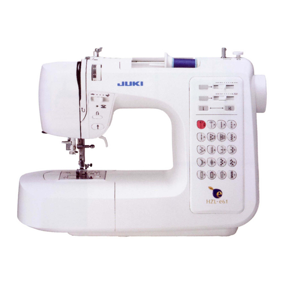
[2] NAMES OF THE RESPECTIVE COMPONENTS Spool pin Thread spool cap Bobbin thread guide Bobbin winding regulator Bobbin winder shaft Thread tension dial Stitch length manual button Stitch length adjusting lever Face cover Stitch width manual button Speed controller Stitch width adjusting lever Bobbin winding monitor Automatic lock stitch button Reverse stitch button... - Page 7 Thread Cutter Needle threader Needle clamp Buttonholing lever Needle Presser foot release lever Presser foot shank Presser foot Feed dog Hook cover release Throat plate button Bobbin case Hook cover Bobbin...
-
Page 8: How To Remove The Outer Components
[3] HOW TO REMOVE THE OUTER COMPONENTS Remove setscrew (1) in the face cover and 1. Face cover remove the face cover. Remove setscrews (2) and (3) in the throat plate and 2. Throat plate remove the throat plate. 3. Base plate and free arm bottom cover Remove setscrews (4), (5) and (6) in the rubber cushion of the base plate, setscrew (7) of the base plate, and height adjusting screw (8). - Page 9 4. Front panel and rear panel Remove setscrews (bottom) (10) and (11) in the front panel (Mas. asm.). (10) (11) Remove setscrews (12), (13) and (14) in the rear panel (asm.) and setscrew (rear) (15) in the front panel (Mas. asm.). (Lift the presser lifting lever when removing screw (15).) (13) (12)
- Page 10 Loosen setscrew (front) (18) in the front panel (Mas. asm.), 6. Front panel setscrew (right) (19) in the front panel main unit and setscrew (bobbin winder) (20) in the front panel main unit after removing the thread spool cover. (20) (18) (19) 7.
- Page 11 On condition that the presser lifting lever is lowered, open a little bit the joint section of the front and rear covers as illustrated in the figure below. (Rear panel) • Remove the convex sections of the front panel and the rear panel from the frame so as to move the convex sections up from the frame as illustrated in the figure below.
-
Page 12: Circuit Board Connection Diagram
[4] CIRCUIT BOARD CONNECTION DIAGRAM [Power circuit board for 120V] CN52 CN53 Lamp (asm.) Power transformer Fuse 2A Fuse 5A CN51 Power switch CN55 CN54 Power circuit board Motor (asm.) connecting wire (asm.) [Power circuit board for 230V] CN52 CN53 Lamp (asm.) Power transformer Fuse 2A... - Page 13 Table of microcomputer circuit board connectors Connector Connection Connector Connection CN 1 Bobbin winder switch (asm.) CN 6 Display circuit board (asm.) CN 2 BH switch base (asm.) CN 7 Power circuit board connecting wire (asm.) CN 3 MP detecting circuit board (asm.) CN 8 Controller receptacle (asm.) CN 4...
-
Page 14: Adjustment Of The Respective Components
[5] ADJUSTMENT OF THE RESPECTIVE COMPONENTS 5-1-1 Adjusting the needle bar height Remove the face cover. Adjustment • Dimension from the bottom end of the needle bar pin to the top surface of the throat plate : 19.7 mm • The needle eyelet inclines to the right by 5° when a needle is attached. How to adjust 1 1. -
Page 15: Feed Dog Height
5-1-3 Feed dog height Remove the needle plate. How to adjust 1. Set the feed amount to “0”. 2. Turn the hand wheel and bring the feed dog to its highest point. 3. Loosen shaft [ b ] and make a clearance between the cam and the top end of the shaft as illustrated in the figure. -
Page 16: Feed Timing
5-1-5 Feed timing After checking the feed dog height and needle bar height, perform this adjustment. The feed timing will affect the tightness of the needle thread. How to adjust 1. Attach HA x 1 #14 needle. Upper side in the rear 2. - Page 17 How to adjust 1. Loosen the setscrew in the hook drive gear which is hidden as observed from the bottom side of the sewing machine when the center of the needle aligns with the top end of the blade of the hook. 1.06 2.
-
Page 18: Clearance Between The Needle And The Blade Point Of The Hook
5-1-7 Clearance between the needle and the blade point of the hook Remove the face cover and the needle plate. How to adjust 1. Set the machine to the zigzag pattern (large) (zigzag width 7 mm). Raise the needle bar by hand from the lowest point of its stroke and make sure that the clearance provided between the blade point of the hook and the needle is 0.05 mm to 0.1 mm at the left and right needle entry points when the blade point of the hook comes to the rear of the center of the needle. -
Page 19: Adjusting The Bobbin Thread Tension
5-1-9 Adjusting the bobbin thread tension Remove the throat plate. How to adjust 1. Position the bobbin case and the tension gauge as illustrated and adjust the adjusting screw (4) so that the tension is 0.1862±0.0098 [N] (19g±1g) with SHAPPE #60 thread. -
Page 20: Adjusting The Needle Thread Tension
5-1-12 Adjusting the needle thread tension Remove the face cover and the front panel. How to adjust 1. Remove the tension knob fixing E ring and remove the thread tension dial presser, the tension knob and the tension cam. 2. Prepare SHAPPE SPAN # 60 and the tension gauge, and pass needle thread from the base tension to the tension disk. -
Page 21: Vertical Position Of The Threader Hook
5-1-14 Vertical position of the threader hook Remove the face cover. How to adjust 1. Attach a household needle HAx1 #11. 2. Turn the hand wheel to bring the needle bar near the highest point of its stroke, and stop it at the position where the setscrew of needle bar guide can be observed. -
Page 22: Adjusting The Position Of The Bh Switch
5-1-16 Adjusting the position of the BH switch Remove the face cover. How to adjust 1. Attach the BH foot and lower the presser foot. 2. Lower the buttonholing. 3. Select BH ( ) with the pattern selector button. 4. Loosen setscrews (5) and (6) in the BH switch base. 5. -
Page 23: Longitudinal Feed
5-1-17 Longitudinal feed Preparation for 1. After turning the power switch OFF, pressing the reverse button, turn the power adjustment switch ON. Then turn the feed manual switch ON while the stitch selection buttons light up in order (Welcome display), and turn OFF the reverse button. Then turn OFF the stitch length manual adjustment button OFF after the welcome display is completed. - Page 24 HOME APPLIANCE H.Q. 8-2-1, KOKURYO-CHO, CHOFU-SHI, TOKYO 182-8655, JAPAN PHONE : (81)3-3480-5034 FAX : (81)3-3480-5037 Copyright © 2003 JUKI CORPORATION. All rights reserved throughout the world. 29365806 03.10 Printed in Japan...