Toro Z593-D Z Master 74264 Operator's Manual
With 52in or 60in turbo force side discharge mower
Hide thumbs
Also See for Z593-D Z Master 74264:
- Operator's manual (64 pages) ,
- Operator's manual (64 pages)
Table of Contents
Advertisement
Advertisement
Table of Contents

Related Manuals for Toro Z593-D Z Master 74264


Summary of Contents for Toro Z593-D Z Master 74264
- Page 1 Form 3353-652 Count on it. Z593-D Z Master ®with 52in or 60in TURBO FORCE ® Side Discharge Mower Model 74264--Serial 250000001 Model 74265--Serial 250000001 Register your product at www.Toro.com Original Instructions (EN)
-
Page 2: Ices
Important calls attention to special mechanical information and Note emphasizes You may contact Toro directly at xw, w, v Toro.com general information worthy of special attention. for product and accessory information, help finding a dealer, or to register your product. -
Page 3: Table Of Contents
Switching the Fuel Tanks ....Adiusting the Parking Brake ....Belt Maintenance ........Using the Rollover Protection System (ROPS) ....Inspecting the Belts ......Think Safety First ......Replacing the Mower Belt ....Operating the Parking Brake ....Replacing the PTO Drive Belt .... Starting and Stopping Replacing... - Page 4 Safety hair, loose clothing or jewelry may get tangled in moving parts. Improper use or maintenance by the operator Inspect the area where the equipment is to be owner can result in injur 7 To reduce the potential used and remove all objects such as rocks, toys for injur B comply with these safeDTinstructions and wire which can be thrown by the machine.
- Page 5 • Always avoid sudden starting or stopping on Keep hands and feet away from the cutting units. a slope. If tires lose traction, disengage the blades and proceed slovdy off the slope. • Never carry passengers and keep pets and •...
- Page 6 7 Wear protective clothing and use insulated tools. Keep all parts in good working condition and all hardware tightened. Replace all worn or damaged decals. Use only Toro approved attachments. Warranty may be voided if used with unapproved attachments.
- Page 7 Fold along appropriate line sLOPE TillS IS A 5+ SLOPE edge.
-
Page 8: Decals
Safety and Instructional Decals Safety decals and instructions are easily visible to the operator and are located near any area of potential danger. Replace any decal that is damaged or lost. 1-523552 _i_ CAUTION 54-9220 ROTATING BLADES! STOP ENGINE BEFORE REACHING UNDERNEATH. - Page 9 103-1636 68-8340 98-4387 Warning--wear hearing protection. 105-7798 98-5954 106-7492...
- Page 10 106-9989 107-1613 107-1857 107-1622...
- Page 11 107-1864 107-1860 107-2102 107-1861...
- Page 12 108-5957 107-2112 THIS COOLING SYSTEM PROTECTED BY: © Shell DEX-COOL ®_Extended Life Antifreeze/Coolant 108-5981 Top off with Shell DEX-COOL ®* Extended Life Antifreeze/Coolant. Suggested change interval is at 4 years or 4,000 hours of service. DEX-COOL is a registered trademark of General Motors Corp.
- Page 13 110-3852 Continuous tone signals Remove the ignition read the instructions the user that engine is overheating. before servicing performing maintenance. 110-3853 110-3851 Cutting/dismemberment Remove the ignition Remove the ignition key and read the instructions before and read the instructions hazard, fan and servicing or performing maintenance.
-
Page 14: Figure
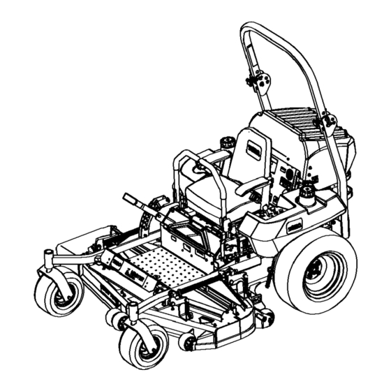
Product Overview Hour Meter The hour meter records the number of hours engine has operated. It operates when the engine is running. Use these times for scheduling regular maintenance (Figure Glow Plug Light The glow plug indicator light turns on when the glow plug button is engaged (Figure 4). - Page 15 Operation In certain conditions, fuel is extremely Note: Determine the left and right sides of the flammable and highly explosive. A fire or machine from the normal operating position. explosion from fuel can burn you and others can damage property. Adding Fuel •...
-
Page 16: System (Rops)
Clean around each fuel tank cap and remove the cap. Add fuel to both fuel tanks, until the level is 1/4 to 1/2 inch (6 to 13 mm) below the bottom of the filler neck. This space in the tank allows the fuel to expand. Do not fill the fuel tanks completely full. - Page 17 5. To raise the roll bar, remove the hairpin cotter pins and remove the two pins (Figure 7). There is no rollover protection when the roll 6. Raise the roll bar to the upright position and bar is in the down position.
-
Page 18: Think Safety First
Think Safety First Please read all safety instructions and symbols in the safety section. I_owing this information could help you or bystanders avoid injur> Operating on wet grass or steep slopes can cause sliding and loss of control. Wheels dropping over edges can cause rollovers, which may result in serious... -
Page 19: Engine
Setting the Parking Brake Set the paring brake; refer to Setting the Paring Brake. 1. Move the motion control levers (Figure 16) out to the neutral lock position. Move the PTO (power take oft) switch to the 2. Pull up and back on the paring brake lever to off position (Figure 12). - Page 20 Release the svdtch after 10 to 15 seconds. The Note: Additional starting cycles may be light will turn off. required when starting the engine for the first time after the fuel system has been completely Turn the key to the start position and the glow without fuel•...
-
Page 21: To)
The Safety Interlock System Operating Power Take Off (PTO) The power take off (PTO) svdtch starts and stops If safety interlock switches are disconnected the mower blades and any powered attachments. or damaged the machine could operate unexpectedly causing personal injury. -
Page 22: Or Backward
and rise slightly from the seat; the engine The farther you move the traction control should stop. levers in either direction, the faster the machine will move in that direction. Sitting on the seat, engage the paring brake, move the PTO switch to off and move To stop, pull the motion control levers to the... -
Page 23: Adjusting The Height-Of-Cut
Disengage the PTO, move the motion control levers to the neutral locked position and set the paring brake. Children or bystanders be injured they move or attempt to operate the tractor Stop the engine, remove the ke), and wait for while it is unattended. -
Page 24: Adjusting The Flow Baffle
Swing the lever back over to tighten the baffle and cam locks (Figure 21)• If the cams do not lock the baffle into place or it is too fight, loosen the lever and then rotate the cam lock. Adjust the cam lock until the desired lock:ing pressure is achieved•... -
Page 25: The Seat
• Use in wet conditions. • Lowers the engine power consumption. G000949 • Allows increased ground speed in hea_ T Figure 25 conditions. I. Adjustment lever • This position is similar to the benefits of the Toro SFS mower. -
Page 26: The Seat
Unlatching the Seat The machine will not drive unless by-pass valves are turned in. Push the seat latch rearward to unlatch the seat. This vdll allow access to the machine under the seat (Figure 26). G000950 G000966 Figure 26 Seat latch Seat Figure 27 Fuel cap... -
Page 27: Loading Machines
Loading Machines Use extreme caution when loading units on trailers Without the grass deflector, discharge or trucks. One full width ramp that is wide enough cover, or complete grass catcher assembly to extend beyond the rear tires is recommended mounted in place, others instead of individual ramps for each side of the... -
Page 28: Operating Tips
Operating Tips Fast Throttle Setting Loading a unit onto a trailer or truck increases the possibility of backward For best mowing and maximum air circulation, tip-over and could cause serious injury operate the engine at the fast throttle position. death. is required to thoroughly cut grass clippings,... - Page 29 Check the cutter blades daily for sharpness, and for aW wear or damage. File down aW nicks and sharpen the blades as necessar 7 If a blade is damaged or worn, replace it immediately with a genuine TORO replacement blade.
-
Page 30: Maintenance
Maintenance Recommended Maintenance Schedule(s) Maintenance Service Maintenance Procedure I nte rva I Afterthefirst8 operating • Check cooling system level. hours • Check the hydraulic fluid. After the first 25 • Change the hydraulic filter and oil. operating hours After the first 50 •... - Page 31 If you leave the key in the ignition switch, someone could accidently start the engine seriously injure you or other bystanders. Remove the key from the ignition and disconnect the wire from the spark plug(s) before do any maintenance. Set the wire aside so that it does...
-
Page 32: Engine Maintenance
7. Grease the PTO drive belt idler arm Greasing Mower Deck (Figure 31). Belt Idlers 8. Grease the pump belt idler arm (Figure 31). The mower deck must be lubricated weeMy or every 25 hours• Grease with No. 2 general purpose lithium base or molybdenum... -
Page 33: Oil
appear as bright spots. If the filter is damaged discard G001048 Figure 33 G001049 Air filter body Air cleaner cover Air filter Latches Figure 32 Air cleaner cover Air filter body Air filter Latches Servicing the Engine Oil Installing Filter Change engine oil:... - Page 34 7780 -3o -2o Jo G001061 Figure Checking Engine Oil Level Note: Check the oil when the engine is cold• G001057 Disengage the PTO, move the motion control Figure levers to the neutral locked position and set the parMng brake. Rear left side of machine Oil dipstick Metal end Stop the engine, remove the ke), and wait for...
- Page 35 Figure 38 Engine Oil fill cap G001058 Figure 36 To add oil to the engine, locate and use a hose Back of machine Drain plug and funnel for adding oil (Figure 39). Add oil slow135chec_ng the level with the dipstick frequently until the level reaches the Adding Engine upper hole on the dipstick.
-
Page 36: Fuel System Maintenance
filter on by hand until the gasket contacts the Important: the oil very slowly oil filter adapter. Tighten 1/2 to 3/4 turn more. do not block the opening of the filler hole (Figure 40). If you add oil too fast or block 4. -
Page 37: Servicing The Fuel Tank
them more frequently under extremely dusty or dirty conditions. Battery electrolyte contains sulfuric acid which is a deadly poison and causes severe Replacing Fuel Filter burns. Ensure that an Authorized Service Dealer replaces Do not drink electrolyte and avoid contact the fuel filter and any components for the fuel with... - Page 38 Slide the red terminal boot off the positive (red) battery terminal. Then remove positive (red) battery cable (Figure 43). G000959 Figure 43 G001050 Figure 44 Negative Battery Post Red (+) cable Positive Battery Post Black (-) cable Battery Wing nut Hydraulic tank Right side fuel tank Bolts...
-
Page 39: Servicing The Fuses
Charging Battery Fuse: • Ignition, FI-30 amp, blade-type • Radiator fan, F2-30 amp, blade-type Charging the battery produces gasses that 1. Unlatch the engine hood and raise the engine explode. hood to gain access to fuse holder (Figure 46). Never smoke near the battery... -
Page 40: The Trac -Tdng
Drive System Maintenance Adjusting the Tracking The machine has a knob for adjusting the tracing located under the seat. Important: Adjust the handle neutral hydraulic pump neutral before adjusting the tracking. Refer to Adjusting the Handle Neutral in Controls System Maintenance, page 48 and Adjusting... - Page 41 GO01055 Figure 48 Checking the Wheel Slotted Check after every 500 operating hours. The slotted nut needs to be torqued to 125 ft-lb (1 r0 N.m). 1. Disengage the PTO, move the motion control levers to the neutral locked position and set Figure 47 the paring brake.
-
Page 42: Adjusting The Caster Pivot Bearing
Servicing the Gear Torque the slotted nut to 125 ft-lb. (170 N°m) (Figure 40). Tighten the nut until the next set of slots line Checking Gear Oil Level up with the hole in the shaft (Figure 49). Use SAE 75W-90 Synthetic Gear Lube. Replace the cotter pin. -
Page 43: System
Cooling System Note: Do not open the radiator cap. Doing this may induce air into the cooling system. Maintenance 1. Position the machine on a level surface, stop the engine, and set the paring brake. Servicing the Cooling System Unlatch the seat and tilt the seat up. -
Page 44: Belt Maintenance
If adjustment is necessar3, repeat the procedures above. 7. Repeat on the opposite side of machine. Figure 54 G001104 Brake lever in engaged Adjusting nut and jam nut position Figure 53 Spring 2-1/2 inch (64 mm) Radiator screen Hydraulic oil cooler Left rear tire Belt Maintenance Changing... -
Page 45: Replacing The Pto Drive Belt
Replacing the PTO Drive Belt Remove the existing belt if needed. Install the new belt around the mower pulleys Squealing when the belt is rotating, blades slipping and the gearbox pulley under the engine when cutting grass, frayed belt edges, burn marks (Figure 56). -
Page 46: Replacing The Pump Drive Belt
G001158 Figure 59 G001157 Pump drive belt Spring loaded idler pulley Clutch Spring Figure 58 PTO Drive belt Spring loaded idler pulley Clutch Gear box Spring Clutch stop bracket Replacing and Tensioning the Alternator Belt Replacing the Pump Drive Check the alternator belt for wear after every ) ( hours of operation. - Page 47 Install the fan and fan plate to the machine with the 2 bolts previously removed (Figure 61)• Install the oil cooler with the 4 bolts previously removed (Figure 61)• Install the oil cooler shield and engine straps to the rear frame with the 4 bolts previously removed (Figure...
-
Page 48: Adjusting The Control Handle Neutral Position
Begin with either the left or right motion control lever. Move the lever to the neutral position but not locked (Figure 63)• Pull the lever back until the clevis pin (on arm below pivot shaft) contacts the end of the slot (just beginuing to put pressure on the spring) (Figure 63). -
Page 49: Starting And Stopping The Engine
Clean the area around filler neck of hydraulic tank (Figure 65). Remove the cap from the filler neck. Look inside to check if there is fluid in the reservoir (Figure 65). If there is no fluid, add fluid to the reservoir until it reaches the cold level of the baffle. - Page 50 Hydraulic fluid escaping under pressure can penetrate skin and cause injury. If hydraulic fluid is injected into the skin it must be surgically removed within a few hours by a doctor familiar G001044 with this type of injury. Gangrene Figure 66 result if this is not done.
-
Page 51: Setting The Hydraulic Pump
both wheels will not drive, refer to Bleeding Hydraulic System. Hydraulic fluid escaping under pressure 13. Recheck the fluid level while the fluid is warm. penetrate skin and cause injury. The fluid should be behveen cold and hot. If hydraulic fluid is injected into the skin 14. -
Page 52: Neutral Position
Engine must be running so motion control adjustment can be performed. Contact with moving parts or hot surfaces cause personal injury. Keep hands, feet, face, clothing and other body parts away from rotating parts, muffler other hot surfaces. Raise the frame and block up the machine drive wheels can rotate freely. -
Page 53: Positions
Mower Deck Tighten the locknuts at the ball joints (Figure 70). Maintenance Leveling the Mower at Three Positions Important: There are only three measuring positions needed to level the mower. Setting Up the Machine 1. Position mower on a flat surface. Disengage the PTO, move the motion control levers to the neutral locked position and set the paring... -
Page 54: Adjusting Front-To-Rear Mower Pitch
T- T- T G001042 Figure Figure Measure at B and C Real chain Adjustment bolt Measure here from blade Rear support arm Front swivel to hard surface Bolt Front support Jam Nut If the measurements at positions B or C are not correct, loosen the bolt attaching... -
Page 55: Adjusting The Compression Spring
If a blade is Adjust this distance, by loosening the spring damaged or worn, replace it immediately with a jam nut and turning the nut in front of each genuine Toro replacement blade. For convenient spring (Figure 74). Turning the nut clockwise sharpening... - Page 56 A, of ensure optimum performance and continued the blades (Figure 76)• Note this dimension. safety conformance of the machine, use genuine TORO replacement blades. Replacement blades made by other manufacturers may result in non-conformance...
- Page 57 Contact with a sharp blade can cause serious G000277 injury. Figure 78 Wear gloves or wrap sharp edges of the Blade Balancer blade with a rag. Hold the blade end using a rag or thickly-padded glove. Installing Blades Remove the blade bolt, spring disk and blade 1.
-
Page 58: Waste Disposal
Replacing Grass Deflector An uncovered discharge opening could allow the lawn mower to throw objects the operator's or bystander's direction result in serious injury. Also, contact with the blade could occur. Never operate the lawn mower unless you install a cover plate, a mulch plate, G000977... -
Page 59: Storage
Storage Add a petroleum based stabilizer/conditioner to fuel in the tank. Follow mixing instructions from Cleaning Storage the stabilizer manufacturer. Do not use an alcohol based stabilizer (ethanol or 1. Disengage the power take off (PTO), set the methanol). paring brake, and turn the ignition key to Off. - Page 60 Troubleshooting Problem Possible Cause Corrective Action Starter does not crank Blade control (PTO) Move blade contro (PTO) engaged. to disengaged. Parking brake is not on. Set the parking brake. Sit on the seat. Operator is not seated. Battery is dead. Charge battery.
- Page 61 Problem Possible Cause Corrective Action Machine does not drive. By pass valve is not Tighten by pass valve. closed tight. Drive or pump belt is Change the belt. worn, loose or broken. 3. Drive or pump belt is off Change the belt.
- Page 62 Problem Possible Cause Corrective Action Blades do not rotate. Check belt tension. Drive belt is worn, loose or broken. Install drive belt Drive belt is off pulley. check adjusting shafts belt guides correct position. Install deck belt. Deck belt is worn, loose or broken.
-
Page 63: Schematics
"V ACCESORY 2CA Opt. CONNECTOR (IGNITION) I° SWITCH START NO CONNECTI _GND ALTERNATOR /REGULATOR M6 stud mVl_ TERMINAL VIEW FROI_ (PTO) BACK OF SWITCH B_pK SHOWN OFF POSITION (SEAT SW6sw) SHOWN WI" OPERATOR (BRAKE) SHOWN WITH IN SEAT PARK BRAKF 91-A DISENGAG D[__._... - Page 64 Canada Customers who have purchased Toro products exported from the United States or Canada should contact their Toro Distributor (Dealer) to obtain guarantee policies for your country, province, or state. If for any reason you are dissatisfied with your Distributor's...