Table of Contents
Advertisement
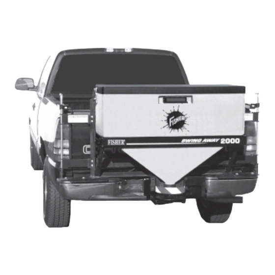
LOW PROFILE TAILGATE
Read this manual before installing or operating
the spreader.
This manual supersedes all editions with an earlier date.
This manual is for FISHER
SPREADERS
Owner's Manual
CAUTION
Low Profile Spreaders with serial numbers
®
Model 1000 - (10003 - )
Model 2000 - (20364 - )
April 1, 2005
Lit. No. 94431
Advertisement
Table of Contents

Related Manuals for Fisher 1000-(10003)


Summary of Contents for Fisher 1000-(10003)
- Page 1 SPREADERS Owner’s Manual Read this manual before installing or operating the spreader. This manual supersedes all editions with an earlier date. This manual is for FISHER CAUTION Low Profile Spreaders with serial numbers ® Model 1000 - (10003 - )
-
Page 2: Table Of Contents
Starting the Motor with Variable Speed (PWM) Control... 12 Stopping the Motor with Variable Speed (PWM) Control... 12 REMOVING THE SPREADER ... 13 Removing the Fixed Mount Spreader ... 13 Removing the Fixed Mount Brackets ... 13 Removing the Receiver Mount Spreader ... 13 Removing the SWING AWAY Spreader ... -
Page 3: Preface
Low Profile tailgate spreader. Please read this manual carefully and follow all recommendations. This will help ensure profitable and trouble-free operation of your spreader. Keep this manual accessible. It is a handy reference in case minor service is required. Lit. No. 94430/94431... -
Page 4: Safety Information
• Before servicing the spreader, wait for conveyor or spinner to stop, then lock out power. • Do not climb into or ride on spreader. April 1, 2005 SAFETY INFORMATION Overloading could result in an accident or damage. -
Page 5: Torque Chart
NOTE: Lubricate grease fittings after each use. Use a good quality multi-purpose grease. NOTE: Airborne noise emission during use is below 70 dB(A) for the spreader operator. Lit. No. 94430/94431 SAFETY INFORMATION Torque Chart Read instructions before assembling. Fasteners should be finger tight until instructed to tighten according to the torque chart. - Page 6 Warning/Caution Label Located on both sides WARNING • DO NOT EXCEED GVWR OR GAWR WITH SPREADER AND LOAD. • TURN SPREADER OFF BEFORE FILLING, ADJUSTING, OR CLEANING. • BYSTANDERS TO STAY A MINIMUM OF 25 FEET AWAY FROM OPERATING SPREADER.
- Page 7 Warning/Caution Label Located on both sides WARNING • DO NOT EXCEED GVWR OR GAWR WITH SPREADER AND LOAD. • TURN SPREADER OFF BEFORE FILLING, ADJUSTING, OR CLEANING. • BYSTANDERS TO STAY A MINIMUM OF 25 FEET AWAY FROM OPERATING SPREADER.
-
Page 8: Loading
Do not exceed GVWR or GAWR ratings as found on the driver-side vehicle door cornerpost. NOTE: If spreader and ice control material loading is in doubt weigh vehicle for compliance with vehicle ratings. NOTE: Use only dry, free-flowing granular materials with this spreader. -
Page 9: Mounting The Spreader
1/2" locknut. Attach the other hole in the top bracket to the bed rail with one 1/2" cap screw and one 1/2" locknut. 2. Place the spreader on the bumper and line up the holes in the bottom feet with the holes in the bumper. -
Page 10: Swing Away ® Spreader
3/8" cap screws, three 3/8" plain washers, any shims and three 3/8" locknuts per side. 4. Place the spreader on the base plates and insert the hinge pins. Secure the hinge side by installing one 1/4" cap screw and 1/4" locknut through the hole in the base plate boss and hinge pin. -
Page 11: Operating The Spreader
• If you are tired, pull off in a safe place and rest. • Spreader size reduces driver visibility to the rear of the vehicle due to spreader size and location. We recommend OSHA compliant backup alarm for all governed employers. -
Page 12: Spreader Control
NOTE: If the truck ignition is turned off while the spreader is running, the motor will stop. If there are problems while operating the spreader, refer to the Troubleshooting section in this manual. NOTE: Always place the cover on the hopper to prevent moisture buildup. -
Page 13: On/Off Control (Late Style)
NOTE: Always place the cover on the hopper to SPINNER prevent moisture buildup. Do not let the spreader sit idle with material in the hopper for an extended period of time. This can cause the material to compact and reduce or stop the flow of material. -
Page 14: Variable Speed (Pwm) Control
Before starting the spreader, the driver shall verify all bystanders are a minimum of 25 feet away from operating spreader. 1. To start the spreader motor, press the power switch to the START/BLAST position and release. This is a momentary position and the power switch will automatically return to the ON position when released. -
Page 15: Removing The Spreader
3/8" cap screws and locknuts that fasten the spreader to the top brackets. 4. Remove the spreader from the vehicle and stand in an upright position. This may require additional support. Removing the Fixed Mount Brackets 1. -
Page 16: Maintenance
After every use, clean the spreader, but first disconnect the electrical plug located between the spreader and the truck. The spreader can be cleaned using tap water or a high pressure washer. A long handle brush can be used to aid cleaning. -
Page 17: Drive Belt Replacement
Lit. No. 94430/94431 MAINTENANCE Recycle When your spreader has performed its useful life, the majority of its components can be recycled as steel. Gear oil shall be disposed of according to local regulations. Balance of parts made of plastic shall be disposed of in customary manner. -
Page 18: Bearing And Set Screw Maintenance
Bearing and Set Screw Maintenance Disconnect the electrical plug between the spreader and the truck before performing any maintenance. 1. Tighten all set screws shown after every 60 hours of use. 2. Grease the top and bottom drive shaft bearings as shown. -
Page 19: Pin Harness Wiring Diagram
30 Amp Fuse 14 Ga. Black 8 Ga. Black 14 Ga. Yellow 14 Ga. Orange Accessory Circuit (12 AMP MAX) Vehicle Wiring Harness Spreader Wiring Harness CHMSL Assy 14 Ga. Black 14 Ga. Yellow Accessory Circuit Cab Control Red Connector... -
Page 20: Pin Harness Wiring Diagram
Black April 1, 2005 Late Style (Adapter Required) Speed Control White Black Adaptor Black Fuse Butt Connector Power Lead Black Vehicle Side Spreader Side Black White CHMSL Signal Black White Stoplight Vehicle Harness White Black Battery Harness Vehicle Harness Wiring Harness... -
Page 21: Troubleshooting
Some of the solutions on the following page are complicated. If you are not properly trained or experienced in electrical or mechanical repairs, take you spreader to your local outlet for repairs. ON/OFF Control PROBLEM Ice control material not flowing... -
Page 22: Mechanical Problems - Variable Speed (Pwm) And On/Off Control
1. Feedgate is closed. 2. Obstruction in hopper. 1. Deflector out of adjustment. SUGGESTED SOULUTION 1. Unplug the spreader harness and tag out if required. Check hopper for material and free any bridged material. 1. Unplug the spreader harness and tag out if required. -
Page 23: Early Production - 2 Pin Harness
– The motor is turning Lit. No. 94430/94431 TROUBLESHOOTING POSSIBLE CAUSE Bridging of material in hopper Spreader Control power switch is in the OFF position Spreader Control circuit breaker is tripped (ON/OFF control only) Battery lead in-line fuse is blown... - Page 24 Fisher Engineering outlets or spreader owner is granted. Fisher Engineering reserves the right its product improvement policy to change construction or design details and furnish equipment when so altered without reference to illustrations or specifications used. Fisher Engineering and the vehicle manufacturer may require and/or recommend optional equipment for spreaders.