
Related Manuals for McIntosh D100


Summary of Contents for McIntosh D100
- Page 1 McIntosh Laboratory, Inc. 2 Chambers Street Binghamton, New York 13903-2699 Phone: 607-723-3512 www.mcintoshlabs.com D100 Digital Preamplifier Owner’s Manual...
-
Page 2: Safety Instructions
The lightning flash with arrowhead, within an equilateral The exclamation point within an equilateral triangle is triangle, is intended to alert the user to the presence of intended to alert the user to the presence of important uninsulated “dangerous voltage” within the product’s en- operating and maintenance (servicing) instructions in the closure that may be of sufficient magnitude to constitute literature accompanying the appliance. -
Page 3: Table Of Contents
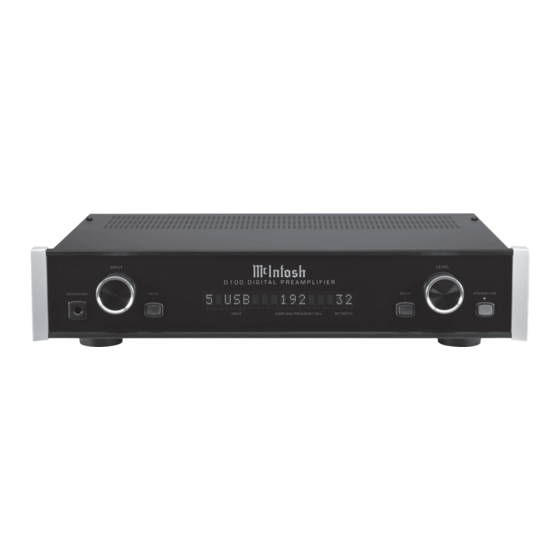
Thank You Customer Service Front Panel: Your decision to own this McIntosh D100 Digital Pre- If it is determined that your McIntosh product is in amplifier ranks you at the very top among discrimi- need of repair, you can return it to your Dealer. You Front Panel Displays, Controls, Push-buttons and Jack .............. -
Page 4: General Information
Below is the Pin configuration for the XLR Balanced to the D100 Digital Preamplifier. Output Connectors on the D100. Refer to the diagram 2. The Main AC Power going to the D100 and any for connections: other McIntosh Component(s) should not be applied... -
Page 5: Introduction
Controlled Attenuator System with a tracking accuracy of 0.1dB. The famous McIntosh Illuminated Glass Front Panel Performance Features ensures the pristine beauty of the D100 will be re- • Dual Function • Alphanumeric Fluorescent Display tained for many years. -
Page 6: Dimensions
Dimensions Dimensions The following dimensions can assist in determining the best location for your D100. There is additional information on the next page pertaining to installing the D100 into cabinets. Front View of the D100 " 44.5cm " 9/32 "... -
Page 7: Installation
Installation Installation " The D100 can be placed upright on a table or shelf, 43.5cm standing on its four feet. It also can be custom in- stalled in a piece of furniture or cabinet of your choice. The four feet may be removed from the bottom "... -
Page 8: Rear Panel Connections
AC outlet. signals from a or A/V Control Center Refer to information on the compatible IR back panel of your D100 to Room Sensor determine the correct volt- age for your unit DATA IN receives DIGITAL AUDIO INPUTS OPTICAL... -
Page 9: Connecting To A Power Amplifier
Connecting to a Power Amplifier Connecting to a Power Amplifer There are two different ways the D100 may be oper- Note: If two Power Amplifiers are used, connect the Power Control Output of the first Amplifier to ated in an audio system. The first way as the Main... -
Page 10: Connecting To An Analog Preamplifier Or A/V Control Center
4. Connect any additional Components in a similar manner, as outlined in steps 2 and 3. Data Connection: 5. Connect a Control Cable from the D100 DATA IN Jack to the Analog Preamplifier or A/V Control Center DVD or VIDEO Data Port Input. -
Page 11: Remote Control Push-Buttons
Direct access to the Digital Input (1 - 5) by using the Front Panel Indicated Input Number for source selection Steps thru the Digital Inputs (1 - 5) for source selection Note: Push-buttons whose function is not identified above are for use with other McIntosh Products. -
Page 12: Front Panel Displays, Controls, Push-Buttons And Jack
Setup impedance dynamic Mode for changing operational headphones, for settings private listening MUTE Push-button STANDBY/ON with indicator, mutes Push-button with the audio from the indicator, switches Loudspeakers the D100 ON or OFF (Standby) and resets the microprocessors... -
Page 13: Setup
In some Countries and/or Localities the default setting of remember the brightness preference, High (default set- Note: If the D100 is currently On, proceed to step 2. Auto Power Off Feature is ENABLED. ting) or Low Illumination. Follow the steps below to 1. -
Page 14: How To Operate The D100
Remote The Red LED above the STANDBY/ON Push-but- Control. Refer to figures 50 and 53. ton lights to indicate the D100 is in Standby mode. To switch ON the D100, press the STANDBY/ON Level Control... -
Page 15: How To Operate The D100
Windows Driver Installa- tion and Operation Guide” and “McIntosh USB Audio Windows Driver V_ . _”. Follow the instructions in the USB Audio Windows Driver Installation and Operation Guide McIntosh Laboratory, Inc. 2 Chambers Street Binghamton, New York 13903-2699 Phone: 607-723-3512 www.mcintoshlabs.com... -
Page 17: Photos
Photos... -
Page 18: Specifications
PCM (Pulse Code Modulation) Digital Signal type used for 240 Volts, 50/60Hz at 20 watts CD Discs, etc. 0- 16.0Vrms Balanced Standby Power, less than 0.25 watts Note: Refer to the rear panel of the D100 for the correct Signal To Noise Ratio (A-Weighted) voltage. 110dB Overall Dimensions Width is 17-1/2 inches (44.45cm) -
Page 19: Packing Instruction
Customer Service Depart- 017937 Plastic foot ment of McIntosh Laboratory. Refer to page 4. Please 400159 #10-32 x 3/4” screw see the Part List for the correct part numbers. - Page 20 McIntosh Laboratory, Inc. 2 Chambers Street Binghamton, NY 13903 www.mcintoshlabs.com The continuous improvement of its products is the policy of McIntosh Laboratory Incorporated who reserve the right to improve design without notice. Printed in the U.S.A. McIntosh Part No. 04138700...