Advertisement
Table of Contents
- 1 Table of Contents
- 2 Introduction
- 3 Features
- 4 Guided Tour
- 5 Setting up and Using the Model 5000/7000
- 6 About Equalization
- 7 About Compression
- 8 Appendix A: Impedance Vs. Expected Power
- 9 Appendix B: Block Diagram
- 10 Appendix C:
- 11 Changing the Model 5000/7000 Voltage
- 12 Specifications
- Download this manual
Advertisement
Table of Contents

Summary of Contents for Samson Hartke Systems 5000
- Page 1 BASS AMPLIFIER Hartke Systems 5000/7000...
-
Page 2: Table Of Contents
Introduction 3 Features 4 Guided Tour 5 Front Panel 5 Rear Panel 7 Setting Up and Using the Model 5000/7000 9 About Equalization 11 About Compression 13 Appendix A: Impedance vs. Expected Power 14 Appendix B: Block Diagram 15 Appendix C: Changing the Model 5000/7000 Voltage 16 Specifications 17... -
Page 3: Introduction
You’ll also find a warranty card enclosed—please don’t forget to fill it out and mail it so that you can receive online technical support and so we can send you updated information about these and other Hartke and Samson products in the future. -
Page 4: Features
Features The Hartke Systems Model 5000/7000 Bass Amplifiers offer all the newest concepts in bass amplification. Here are some of their main features: • Two independent amplifiers within each chassis, with power to spare—in the case of the Model 5000, 250 watts per channel (into 4 ohms), and, in the case of the Model 7000, a full 350 watts (into 4 ohms). -
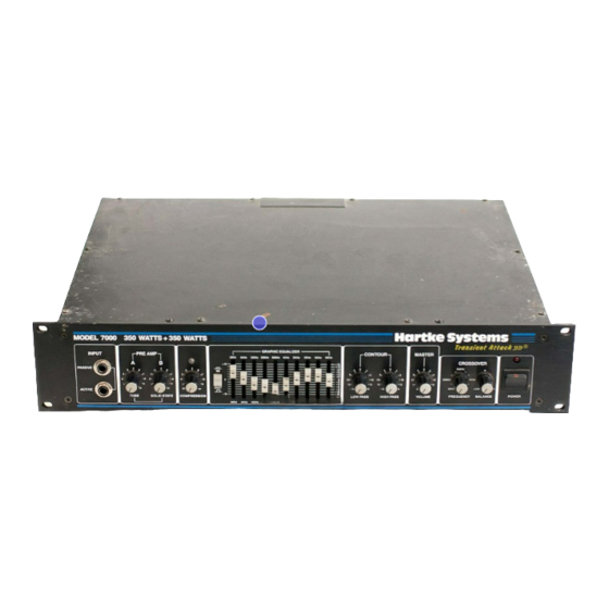
Page 5: Guided Tour
Guided Tour - Front Panel Hartke Systems MODEL 7000 350 WATTS + 350 WATTS ransient Attack GRAPHIC EQUALIZER INPUT PRE AMP CONTOUR MASTER 30Hz 64Hz 125Hz 250Hz 500Hz 1KHz 2KHz 3KHz 5KHz 8KHz CROSSOVER 500Hz PASSIVE 250Hz 1KHz 80Hz HIGH ACTIVE VOLUME FREQUENCY BALANCE... - Page 6 Guided Tour - Front Panel 7. Graphic Equalizer In/Out switch - When pressed in (the “In” position), the Model 5000/ 7000’s graphic equalizer circuitry (as described in #8 below) is operational. When pressed out (the “Out” position), it is bypassed. The provision of this switch allows you to set up a custom equalization curve (an equalization “preset”) with the graphic EQ sliders, which can then be activated with the press of a single button.
-
Page 7: Rear Panel
Guided Tour - Rear Panel SERIAL NUMBER SPEAKER OUTPUTS EFFECT BI-AMP DIRECT OUT HIGH FREQ SEND POST NORMAL MONO GND LIFT ~ AC INPUT 115V/230V 50/60Hz FUSE 20A/250V, 520W (115V) RETURN 10A/250V, 1250W (230V) LOW FREQ ASSEMBLED IN R.O.K 1. Fuse sled - This contains a fuse holder and shows the currently selected voltage rating for your Model 5000/7000. - Page 8 Guided Tour - Rear Panel 5. Fan - The fan provides vital cooling to your Model 5000/7000 . Make sure that it is kept free of all obstructions and that cool, fresh air is accessible at all times. Also, try to ensure that the Model 5000/7000 is used in a dust-free environment.
-
Page 9: Setting Up And Using The Model 5000/7000
Setting Up and Using the Model 5000/7000 Setting up your Hartke Systems 5000/7000 Bass Amplifier is a simple procedure which takes only a few minutes: 1. Remove all packing materials (save them in case of need for future service) and decide where the amplifier is to be physically placed. To avoid potential overheating problems, be sure that the rear panel is unobstructed and that there is good ventilation around the entire unit, particularly behind the rear-panel fan. - Page 10 0 dB (unity gain), so that there is no increase or decrease in level whether the effects are switched in or out. If you have followed all the steps above and are still experiencing difficulties, call Samson Technical Support (516-932-1062) between 9 AM and 5 PM EST.
-
Page 11: About Equalization
About Equalization The Hartke Systems Model 5000/7000 Bass Amplifier gives you enormous con- trol over shaping the sound of your bass, using a process called equalization. To understand how this works, it’s important to know that every naturally occur- ring sound consists of a broad range of pitches, or frequencies, combined together in a unique way. - Page 12 About Equalization To find out how each graphic equalizer slider affects the sound of your particular bass, start with all ten bands flat (that is, all ten sliders at their detented “0” center position). Then, one by one, raise and lower each slider, listening care- fully to the effect of each.
-
Page 13: About Compression
About Compression The dynamic range of a sound is the difference between its loudest and softest points. For example, as you play your bass, you’ll probably find that some notes (for example, notes played on the upper frets of the lowest string) are considerably louder than others. -
Page 14: Appendix A: Impedance Vs. Expected Power
Appendix A: Impedance vs. Expected Power (NOTE: Measurements taken at 1 kHz, Solid State in, and at 3 kHz, Tube in, with 20 Hz - 30 kHz bandpass filter, to give less than 1% THD) Model Speaker Impedance Expected Power 5000 4 ohms 2 x 250 W... -
Page 15: Appendix B: Block Diagram
Appendix B: Block Diagram SEND 50 mV, IN 0 dB TO +4dB FIXED EQ RETURN 2 BAND VR TUBE DETECTOR COMPRESS VR SOLID STATE MIXER 10 BAND EQ POST 50 mV, IN -20 dB TO -30 dB GND. LIFT/ NORMAL 10 BAND OUT 10 BAND IN MASTER SECTION... -
Page 16: Changing The Model 5000/7000 Voltage
Appendix C: Changing the Model 5000/7000 Voltage Following are step-by-step instructions for changing the mains voltage of the Model 5000/7000. WARNING: Before carrying out this operation, remove the power cord! 1: Insert a small screwdriv- 2: Remove fuse sled. er into the slot beneath the fuse sled and gently press in and up. -
Page 17: Specifications
Specifications 1. Input Sensitivity Passive Input 100 k Ohms 20 mv. Active Input 100 k Ohms 60 mv. 2. Rated Output Power Model 5000 2 channels x 250 watts @ 4 ohms 2 channels x 170 watts @ 8 ohms Model 7000 2 channels x 350 watts @ 4 ohms 2 channels x 240 watts @ 8 ohms...