Table of Contents
Advertisement
Owner's Manual
Thank you for purchasing the MIDI keyboard controller PCR-M30/
50/80.
Before using this unit, carefully read the sections entitled:
"USING THE UNIT SAFELY" and "IMPORTANT NOTES"
(OWNER'S MANUAL pp. 2–4). These sections provide
important information concerning the proper operation of
the unit. Additionally, in order to feel assured that you have
gained a good grasp of every feature provided by your new
unit, Owner's manual should be read in its entirety. The
manual should be saved and kept on hand as a convenient
reference.
Copyright © 2004 ROLAND CORPORATION
All rights reserved. No part of this publication may be reproduced in
any form without the written permission of ROLAND CORPORATION.
Advertisement
Table of Contents

Related Manuals for Edirol PCR-M30


Summary of Contents for Edirol PCR-M30
- Page 1 Owner’s Manual Thank you for purchasing the MIDI keyboard controller PCR-M30/ 50/80. Before using this unit, carefully read the sections entitled: “USING THE UNIT SAFELY” and “IMPORTANT NOTES” (OWNER’S MANUAL pp. 2–4). These sections provide important information concerning the proper operation of the unit.
- Page 2 Doing so can damage specific instructions directing you to do so). Refer the cord, producing severed elements and short all servicing to your retailer, the nearest Roland circuits. Damaged cords are fire and shock Service Center, or an authorized Roland hazards! distributor, as listed on the “Information”...
- Page 3 Before using the unit in a foreign country, consult • Try to prevent cords and cables from becoming with your retailer, the nearest Roland Service entangled. Also, all cords and cables should be Center, or an authorized Roland distributor, as placed so they are out of the reach of children.
-
Page 4: Important Notes
However, in certain cases (such as when Placement circuitry related to memory itself is out of order), we regret that it may not be possible to restore the data, and Roland 352a assumes no liability concerning such loss of data. -
Page 5: Additional Precautions
• Unfortunately, it may be impossible to restore the contents of data that was stored in another MIDI device (e.g., a sequencer) once it has been lost. Roland Corporation assumes no liability concerning such loss of data. • Use a reasonable amount of care when using the unit’s buttons, sliders, or other controls;... -
Page 6: Table Of Contents
- Sending MIDI messages to your application - ..............40 MIDI flow..........................40 USB connections with your computer - Using the PCR-M30/50/80 as a MIDI interface - ............. 41 MIDI flow..........................41 When using a MIDI connection ..................... 42 MIDI flow..........................42 Input / output devices.............. - Page 7 KEY VELOCITY(Keyboard: A) ..................95 V-LINK mode .................. 96 Appendices..........97 Memory sets................... 98 Troubleshooting ................104 Problems related to the USB driver..................104 Problems when using the PCR-M30/50/80 ..............110 MIDI implementation..............112 Main specifications..............117 index ..................... 118...
-
Page 8: Contents Of The Package
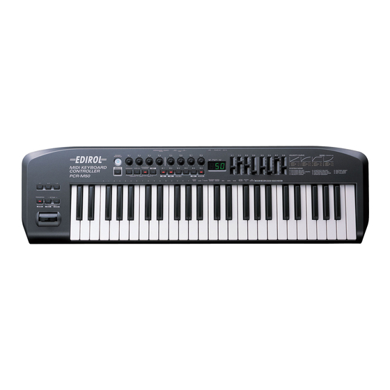
*This figure is the PCR-M30. AC adaptor This is the only AC adaptor you should use with the PCR-M30/50/80. Do not use any AC adaptor other than the supplied one, since doing so may cause malfunction. USB cable Use this to connect the USB connector of your computer with the USB connector of the PCR-M30/50/80. -
Page 9: Quick Page Reference Table
USB MIDI Driver Mode p. 92 Startup Memory p. 93 Factory Reset p. 93 MIDI I/F Mode p. 94 Key Velocity p. 95 Problems related to the USB driver p. 104 Trouble Shooting Problems when using the PCR-M30/50/80 p. 110... -
Page 10: Names Of Things And What They Do
V-LINK compatible video device, you can enjoy various video effects that are linked to your performance. MEMORY Button Accesses memories that are stored within the PCR-M30/50/80. MIDI CH Button Specifies the transmission channel (“current channel”) for the keyboard and bender. - Page 11 Names of things and what they do DEC Button Decreases the value of a setting by one (except in PLAY mode (p. 46)). INC Button Increases the value of a setting by one (except in PLAY mode (p. 46)). VELCRV Button By turning on the power while holding down the [VELCRV] button, you can access a screen that lets you specify the velocity curve.(p.
- Page 12 Operating a controller will cause its current value to appear in the display for a time. Number Lights if the PCR-M30/50/80 is connected to your computer via USB. This will blink when MIDI messages are transmitted via USB or MIDI OUT.
- Page 13 Names of things and what they do Controllers [L1]-[L3] fig.panelC_60 You can assign MIDI messages to these controllers. (➔“Assign MIDI messages” (p. 56)) TRANSPOSE/ENTER Button Use [TRANSPOSE] + [OCTAVE -/+] to transpose the pitch of the keyboard in semitone steps. Also, in any mode except PLAY mode, it functions as the [ENTER] button, which you need to press to confirm the settings you’ve made.
-
Page 14: Rear Panel
USB cable. In this case, the power will be supplied from your computer via the USB cable. To use the PCR-M30/50/80 with bus power, set the power switch to USB. For some computers, the PCR-M30/50/80 may not operate if bus power is used. In this case, use the included AC adaptor. -
Page 15: Setup
Setup This section explains how to install the drivers needed for connecting the PCR-M30/50/80 to a computer, and make the necessary settings. Getting Connected and Installing Drivers (Windows)......(p. 16) Getting Connected and Installing Drivers (Macintosh) ......(p. 29) What is a driver? A “driver”... -
Page 16: Getting Connected And Installing Drivers (Windows)
Getting Connected and Installing Drivers (Windows) Installing the driver The installation procedure will differ depending on your system. Please proceed to one of the following sections, depending on the system you use. • Windows XP users ..............(p. 16) • Windows 2000 users ..............(p. 21) •... - Page 17 2. Connect the AC adaptor to an electrical outlet. devices in the wrong order, you risk causing 3. Use the USB cable to connect the PCR-M30/50/80 to your computer. malfunction and/or damage to speakers and Set the PCR-M30/50/80’s power switch to the ON (DC) position.
- Page 18 Getting Connected and Installing Drivers (Windows) The Found New Hardware Wizard will appear. If the Found New Select “Install from a list or specific location (Advanced),” and click Hardware Wizard asks [Next]. you whether you want to fig.2-7_40 connect to Windows Update, choose “No”...
- Page 19 Getting Connected and Installing Drivers (Windows) If the “What action do you want Windows to take?” (Step 4) setting was not set to “Ignore,” a “Hardware Installation” dialog box will appear. A dialog box with a “!” symbol will appear. 1.
- Page 20 Getting Connected and Installing Drivers (Windows) Giving priority to background services In Windows XP, make settings to give priority to background services. To ensure that MIDI processing occurs smoothly, use the following procedure to make settings. Open the System Properties dialog box. 1.
-
Page 21: Windows 2000 Users
Getting Connected and Installing Drivers (Windows) Windows 2000 users Log on to Windows as a Disconnect all USB cables except for a USB keyboard and USB mouse (if user with administrative used). privileges (such as Administrator). Open the System Properties dialog box. 1. - Page 22 2. Connect the AC adaptor to an electrical outlet. devices in the wrong order, you risk causing 3. Use the USB cable to connect the PCR-M30/50/80 to your computer. malfunction and/or damage to speakers and Set the PCR-M30/50/80’s power switch to the ON (DC) position.
- Page 23 Getting Connected and Installing Drivers (Windows) The Files Needed dialog box will appear. Specify the drive name of your CD-ROM drive. Input the following into the “Copy files from” field, and click [OK]. (drive name): \DRIVER\USB_XP2K If the “File signature verification” (Step 4) setting was not set to “Ignore,” a “Digital Signature Not Found”...
- Page 24 Getting Connected and Installing Drivers (Windows) Giving priority to background services In Windows 2000, make settings to give priority to background services. If you fail to make this setting, you may experience interruptions in the sound. To ensure that MIDI processing occurs smoothly, use the following procedure to make settings.
-
Page 25: Windows Me/98 Users
2. Connect the AC adaptor to an electrical outlet. a protection circuit. A brief interval (a few seconds) 3. Use the USB cable to connect the PCR-M30/50/80 to your computer. after power up is required before the unit will operate Set the PCR-M30/50/80’s power switch to the ON (DC) position. -
Page 26: Settings And Checking ~Specifying The Midi Input/Output Destination
~Specifying the MIDI input/output destination~ Windows XP users Make the following settings so that you can use the MIDI functionality of the PCR-M30/50/80. For a connection diagram, refer to “Basic connections and MIDI flow” (p. 40). Open Control Panel. Click the Windows start menu, and from the menu that appears, select Control Panel. -
Page 27: Windows 2000 / Me Users
Getting Connected and Installing Drivers (Windows) Windows 2000 / Me users Make the following settings so that you can use the MIDI functionality of the PCR-M30/50/80. For a connection diagram, refer to “Basic connections and MIDI flow” (p. 40). Open Control Panel. -
Page 28: Windows 98 Users
Getting Connected and Installing Drivers (Windows) Windows 98 users Make the following settings so that you can use the MIDI functionality of the PCR-M30/50/80. For a connection diagram, refer to “Basic connections and MIDI flow” (p. 40). Open Control Panel. -
Page 29: Getting Connected And Installing Drivers (Macintosh)
Getting Connected and Installing Drivers (Macintosh) The installation procedure will differ depending on your system. Please proceed to one of the following sections, depending on the system you use. • Mac OS X users................. (p. 29) • Mac OS 9 users ................. (p. 32) Mac OS X users Installing the driver If the “Authenticate”... -
Page 30: Mac Os Settings
2. Connect the AC adaptor to an electrical outlet. malfunction and/or damage to speakers and 3. Use the USB cable to connect the PCR-M30/50/80 to your computer. other devices. Set the PCR-M30/50/80’s power switch to the ON (DC) position. Connect the cable to the Open the Applications folder of your Macintosh hard disk. -
Page 31: Software Settings
Getting Connected and Installing Drivers (Macintosh) Connect the ▼ and ▲ symbols (which signify the outputs and inputs) of the EDIROL PCR icon to those of the New External Device icon by using the mouse to drag between them. Use the mouse to drag a connection Close the Audio MIDI Setup. -
Page 32: Mac Os 9 Users
Getting Connected and Installing Drivers (Macintosh) Mac OS 9 users Installing the driver OMS can be found in the Use either OMS or FreeMIDI as the MIDI driver. OMS 2.3.8 E folder within The included PCR driver is an add-on module for using the PCR with OMS the OMS (Mac OS 9,8) or FreeMIDI. -
Page 33: Setting The Driver
2. Connect the AC adaptor to an electrical outlet. other devices. 3. Use the USB cable to connect the PCR-M30/50/80 to your computer. This unit is equipped with Set the PCR-M30/50/80’s power switch to the ON (DC) position. - Page 34 Getting Connected and Installing Drivers (Macintosh) fig.3-6_35 The Create a New Studio Setup dialog box will appear. Click [Cancel]. If you accidentally clicked [OK], click [Cancel] in the next screen. fig.3-8_35 Choose “Open” from the File menu. From the OMS Setting folder that you copied in step 3, select the PCR file, and click [Open].
- Page 35 Getting Connected and Installing Drivers (Macintosh) fig.OMS3 For details on the PCR’s Try playing the keyboard of the PCR. input/output devices, If the arrow beside number 2 or 3 in refer to “Input / output the diagram at right blinks, the devices”...
-
Page 36: Freemidi Settings
By turning on devices in the wrong 2. Connect the AC adaptor to an electrical outlet. order, you risk causing 3. Use the USB cable to connect the PCR-M30/50/80 to your computer. malfunction and/or damage to speakers and other devices. - Page 37 Getting Connected and Installing Drivers (Macintosh) From the File menu, choose Open. If you are unable to select Open, make settings as Select PCR from the FreeMIDI Setting folder you copied in step 3, and click follows. 1.From the File menu, [Open].
- Page 38 Memo...
-
Page 39: Operation
The PCR-M30/50/80 is a controller that transmits MIDI messages. You cannot perform using only the PCR-M30/50/80 by itself. You will need to connect it to a sound module or computer. The various controllers ([R1-R8], [S1-S8], [B1-B6], [L1-L3], [P1, P2]) can be assigned almost any message you want to get the control you need for your particular setup. -
Page 40: Basic Connections And Midi Flow
MIDI flow Turn MIDI I/F MODE OFF as described in “MIDI I/F MODE” (p. 94). fig.flow-USB-b MIDI I/F MODE OFF PCR-M30/50/80 MIDI OUT DEVICE MIDI OUT EDIROL PCR MIDI OUT BULK RECEPTION... -
Page 41: Usb Connections With Your Computer - Using The Pcr-M30/50/80 As A Midi Interface
Basic connections and MIDI flow USB connections with your computer - Using the PCR-M30/50/80 as a MIDI interface - * If you want to use Media Player to play a sound module connected to the PCR’s MIDI OUT connector, make driver settings as described in “Settings and checking~Specifying the MIDI input/ output destination~”... -
Page 42: When Using A Midi Connection
MIDI OUT * Use only the specified expression pedal (EV-5; sold separately). By connecting any other expression pedals, you risk causing malfunction and/or damage to the unit. MIDI flow fig.flow-midi PCR-M30/50/80 MIDI OUT BULK RECEPTION MIDI IN PORT 1 PORT 2 /... -
Page 43: Input / Output Devices
For details on these settings, refer to the owner’s manual for your software. * If you are unable to select the PCR-M30/50/80 in the device settings for your software, it is possible that the driver was not installed correctly. Please reinstall the driver. -
Page 44: Two Midi Ports
The output destination of the MIDI messages transmitted when you operate the PCR-M30/50/80’s knobs, and buttons can be specified separately for each controller. (➔Assign MIDI messages (p. 56)) -
Page 45: Use Midi Functionality
You can switch modes at any time, as shown below. Mode Switching modes Explanation Transmit MIDI messages PLAY mode When you turn on the power, the PCR-M30/50/ by playing the keyboard (p. 46) 80 will start up in PLAY mode. or operating the control- lers. -
Page 46: Startup Mode
Once you have finished making settings, try playing the keyboard. When you play the keyboard in PLAY mode, MIDI messages are sent to the application. * Since the PCR-M30/50/80 does not contain a sound generator, you cannot play MIDI data using the PCR-M30/50/80 alone. -
Page 47: Features Useful When Playing
Octave Shift and Transpose can be set independently. To switch the PCR-M30/50/80 to PLAY mode... When you turn on the power, the PCR-M30/50/80 will start up in PLAY mode. To return to PLAY mode from another mode (➔“Setting the MIDI Transmit Channel” (p. 48)), press the button of the current mode (i.e., the button that is lit). -
Page 48: Setting The Midi Transmit Channel
Use MIDI functionality Setting the MIDI Transmit Channel To control your sound module, set the PCR-M30/50/80’s current channel to the MIDI receive channel that’s selected on your sound module. Use MIDI Channel mode to set the current channel. Current channel The current channel is the transmit channel for the keyboard, Bender Lever. - Page 49 If you want to input decimal numbers, press the [DECIMAL] button. If you want to input hexadecimal numbers, press the [HEX] button. * When you turn on the power, the PCR-M30/50/80 will start up in Decimal mode. Decimal and hexadecimal numbers correspond as follows.
-
Page 50: Selecting Sounds On A Sound Module (Sending Program Change / Bank Select Massages)
Use MIDI functionality Selecting Sounds on a Sound Module (Sending Program Change / Bank Select Massages) To select a sound on your MIDI sound module, transmit a Program Change in Program Change mode. To select a sound from a different bank, first use Bank mode to transmit a Bank Select message that switches the bank. -
Page 51: Program Change Mode (Program Change)
Use MIDI functionality Program Change mode (PROGRAM CHANGE) This mode lets you transmit a program change message on the Current channel (p. 48). fig.PC-1_75 fig.program Press the [PROGRAM CHANGE] button. The [PROGRAM CHANGE] button will light. The display will indicate the program change that was transmitted most recently. -
Page 52: Bank Mode (Bank)
Use MIDI functionality Bank mode (BANK) This mode lets you transmit a bank select (MSB, LSB) message on the Current channel (p. 48). The program change message you most recently transmitted (specified) in Program Change mode (p. 51) will also be transmitted following the bank select message. fig.BANK-1_75 fig.bank Simultaneously press the [PROGRAM CHANGE] button and [MIDI CH]... -
Page 53: Transmitting A Reset Message (What To Do If There Are "Stuck" Midi Notes)
Use MIDI functionality Transmitting a Reset message (What to do if there are “stuck” MIDI notes) If notes on a connected MIDI sound module become “stuck,” or if there is something wrong with the sound, you can execute the Panic function to solve the problem. When you execute the Panic function, All sounds off, All notes off, and Reset all controllers messages will be transmitted on all channels. -
Page 54: Changing The Memory Sets
For details on customizing (editing) the controller settings, refer to “Assign MIDI messages” (p. 56). If you edit the controller settings of a memory you recall, and want to keep your changes, you must save the memory before powering down the PCR-M30/50/80. For the procedure, refer to “Saving a memory set” (p. 84). -
Page 55: Transmitting The Current Controller Values All At Once
Use MIDI functionality Transmitting the current controller values all at once Once you have set the various controllers to the desired settings, you can transmit a detailed description of this state in the form of a “snapshot.” When you execute this function, the current values of the controllers [R1-R8] or [S1-S8] will be transmitted. -
Page 56: Assign Midi Messages
Use MIDI functionality Assign MIDI messages You can assign the following functions to a controller. You will use Edit mode to assign MIDI messages. MIDI Message Assigning method ➔NOTE ASSIGN (p. 57) NOTE ➔AFTERTOUCH ASSIGN (p. 60) AFTERTOUCH ➔CONTROL CHANGE ASSIGN (p. 63) CONTROL CHANGE ➔PROGRAM CHANGE ASSIGN (p. -
Page 57: Note Assign
Use MIDI functionality NOTE ASSIGN Here’s how to assign a Note message to a controller. In addition to being used to play sounds, note messages can also be used to control a sequencer. Mode Keyboard Velocity Port Basic mode 100 (64H) PORT 1 Advanced mode Assignable... -
Page 58: Advanced Mode
Use MIDI functionality ■ Advanced mode Advanced mode 1 of NOTE ASSIGN lets you specify the velocity value in addition to the items of Basic mode. 1. Press the [EDIT] button. 2. Slightly move the controller to which you want to assign a Note message. In the case of a button, press that button. - Page 59 Use MIDI functionality Specifying the button mode When you make Assign settings in Edit mode(p. 56) to assign a message to a button, you must specify the operating mode of the button (button mode). When you use a button as a controller, turning the button on will transmit the maximum specified value, and turning it off will transmit the minimum value.
-
Page 60: Aftertouch Assign
Use MIDI functionality AFTERTOUCH ASSIGN Here’s how to assign an Aftertouch message to a controller. Mode Keyboard Message Value range Port Basic mode Channel Pressure 0-127(00-7FH) Port 1 Advanced mode 1 Channel Pressure Upper and lower limits are assignable Assignable Advanced mode 2 Polyphonic Key Pressure 0-127(00-7FH) Port 1... - Page 61 Use MIDI functionality ■ Advanced mode 1-3 Advanced mode 1 of AFTERTOUCH ASSIGN lets you specify the upper and lower limits of the aftertouch value in addition to the items of Basic mode. Advanced modes 2 and 3 let you specify an aftertouch message for an individual note (Polyphonic Key Pressure) instead of specifying the channel.
- Page 62 Use MIDI functionality Specifying the range of values (upper and lower limits) If in Edit mode you selected an Assign type (p. 56) that lets you specify the range of values, you will need to specify the upper limit and lower limit of the value. Normally, when using Decimal input mode, the value you are specifying appears in the display as a three digit number.
-
Page 63: Control Change Assign
Use MIDI functionality CONTROL CHANGE ASSIGN Here’s how to assign a control change message to a controller. Mode keyboard Value range Port Basic mode 0-127(00-7FH) PORT 1 Advanced mode 1 Upper and lower limits are assignable Assignable Advanced mode 2 Simulates a rotary encoder Assignable ■... - Page 64 Use MIDI functionality ■ Advanced mode 1 Advanced mode 1 of CONTROL CHANGE ASSIGN lets you specify the upper and lower limits of the control change value in addition to the items of Basic mode. 1. Press the [EDIT] button. 2.
- Page 65 Use MIDI functionality ■ Advanced mode 2 Advanced mode 2 simulates the operation of a conventional rotary encoder. If this is assigned to a controller, moving that controller toward the right (upward) of center will have the same effect as turning the encoder clockwise, and moving the controller toward the left (downward) of center will have the same effect as turning the encoder counterclockwise.
-
Page 66: Program Change Assign
Use MIDI functionality PROGRAM CHANGE ASSIGN Here’s how to assign a program change message to a controller. Mode Number Effect Bank Port Basic mode Fixed value Not output PORT 1 Advanced mode 1 Upper and lower limits are assignable Not output PORT 1 Advanced mode 2 Fixed value... - Page 67 Use MIDI functionality ■ Advance mode 1, 2 Advanced mode 1 of PROGRAM CHANGE ASSIGN lets you specify the upper and lower limits of the program change value. Advanced mode 2 lets you transmit BANK LSB/MSB settings in addition to the program change. 1.
- Page 68 Use MIDI functionality ■ Advanced modes 3 and 4 Advanced mode 3 lets you assign the Program Change Decrement function (PC DEC) to a controller. Advanced mode 4 lets you assign the Program Change Increment function (PC INC) to a controller.
-
Page 69: Rpn/Nrpn Assign
Use MIDI functionality RPN/NRPN ASSIGN Here’s how you can assign an RPN or NRPN message to a controller. Mode Keyboard Data entry MSB (CC#6) range Data entry LSB (CC#38) range Port Basic mode 0-127(00-7FH) Not transmitted PORT 1 Advanced mode 1 Upper and lower limits are assignable 00-7FH Assignable fig.edt... - Page 70 Use MIDI functionality fig.BANK-3 Use the [DEC][INC] buttons or the [0]-[F] keys to specify the RPN LSB (CC#100) or NRPN LSB (CC#98). *1 Reference Press the [ENTER] button. If you are making an assignment for a button, specify the button mode. (➔“Specifying the button mode”...
- Page 71 Use MIDI functionality ■ Advanced mode In Advanced mode for RPN/NRPN, you can specify the upper and lower limit of the data entry MSB (CC#6) value when the RPN/NRPN message is transmitted, as well as the various settings available in Basic mode. 1.
-
Page 72: Sys Ex. Assign
Use MIDI functionality SYS EX. ASSIGN Here’s how you can assign a system exclusive message to a controller. Advanced mode 2 lets you assign a single-byte system message (System realtime message, tune request). Advanced modes 3 and 4 let you assign any desired message.(Input up to 24 bytes) Key- Required Mode number... - Page 73 11. Input the second and subsequent bytes in the same way. 12. After you have input the number of bytes you specified in step 7, the PCR-M30/50/80 will check whether the messages you’ve input are indeed valid MIDI messages. If there is a problem, the display will indicate “ERR.”...
- Page 74 • Inputting channel/block data..........(p. 76) ■ Specifying the checksum The PCR-M30/50/80 can automatically calculate the checksum of a system exclusive message and embed it in the message. In order to use this function, you must use the following procedure to specify the starting location from which the checksum is calculated, and the location at which the checksum is inserted.
- Page 75 Use MIDI functionality ■ Specifying the location of the data Here’s how to specify the location and data type of the variable portion (data) within a system exclusive message. The range of data values will be the default range in the case of Basic mode or Advanced mode 3.
- Page 76 (The block number is not actually a channel, but corresponds to the “part” within a GS sound module. On the PCR-M30/50/80, this corresponds to the channel for the sake of convenience.) For an actual example, refer to Bend Pitch Control (p.
-
Page 77: Examples Of Assigning System Exclusive Messages
Use MIDI functionality Examples of assigning system exclusive messages • GM2 System On ..............(p. 77) • Master Volume ................ (p. 78) • Bend Pitch Control ..............(p. 79) ■ GM2 System On F0 7E 7F 09 03 F7 Here’s how to assign a GM2 System On system exclusive message in Basic mode. 1. -
Page 78: Master Volume
Use MIDI functionality ■ Master Volume F0 7F 7F 04 01 vL vM F7 Since a Master Volume message has a data range of 00 00–7F 7F and we do not need to specify the range, we will use Basic mode. Since the two bytes of data are in the order of LSB and then MSB, we will select “DT3”... - Page 79 Use MIDI functionality ■ Bend Pitch Control Since the GS Bend Pitch Control message has a data range of 40H–58H (0–24 semitones), we will select Advanced mode 1, which lets us specify the range. Since the data format is one byte, we will select “DT0”...
- Page 80 Use MIDI functionality 17. Since the ninth byte is the data area, press the [DATA] key. The display will indicate “DT0.” 18. Confirm what’s indicated and press [ENTER]. 19. Since the ten byte will contain the checksum, press the [CHECKSUM] key to specify the location at which the checksum will be input.
-
Page 81: Tempo Assign
Use MIDI functionality TEMPO ASSIGN You can assign a controller to adjust the speed (20-250) of the F8 Clock message. * In order to transmit F8 Clock messages, the F8 CLOCK setting must be “ON.” (➔“F8 CLOCK ON/OFF” (p. 90)) fig.edt Press the [EDIT] button. -
Page 82: Copying A Midi Message Assignment (Assign Copy)
Use MIDI functionality Copying a MIDI message assignment (ASSIGN COPY) Here’s how a message assigned to a controller can be copied to another controller. fig.edt Press the [EDIT] button. The display will indicate “EDT.” fig.r-1 Slightly move the controller to which you want to copy the assignment (the “copy destination”). -
Page 83: Canceling A Midi Message Assignment (No Assign)
Use MIDI functionality Canceling a MIDI message assignment (NO ASSIGN) Here’s how you can cancel the message assigned to a controller. Once its assignment is cancelled, no message will be transmitted when you operate that particular controller. fig.edt Press the [EDIT] button. The display will indicate “EDT.”... -
Page 84: Saving A Memory Set (Save)
Use MIDI functionality Saving a Memory Set (SAVE) Here’s how to save the settings of the current memory into internal memory. You can save settings into internal memory numbers 1-F. You cannot save to memory number 0 (GM2). * After you edit the settings, perform the “SAVE” operation as needed. If you turn off the power without performing “SAVE,”... -
Page 85: Transmitting/Receiving Bulk Data (Bulk)
All memories will be received as bulk data. The received data will ALL BULK overwrite memories 1-F. fig.rs1 Confirm what’s indicated and press the [ENTER] button. The third digit of the display will blink, and the PCR-M30/50/80 will wait to receive bulk data. - Page 86 Use MIDI functionality About the display in Bulk mode fig.bulk-dis Receive Waiting to receive SINGLE (blinking) BULK 1st digit: indicates Receive mode or 3rd digit: indicates Transmit mode Transmit Waiting to transmit Transmitting/Receiving/Waiting states BULK (blinking) receiving Transmitting 2nd digit: Single Bulk or All Bulk transmitting Transmit bulk data from your sequencer or other device.
- Page 87 Confirm what’s indicated and press the [ENTER] button. fig.bs-1 The third digit of the display will blink, and the PCR-M30/50/80 will wait to transmit bulk data. Press the [ENTER] button. On your sequencer software, specify “PCR 2” as the MIDI input device. For details on this setting, refer to the manual of your sequencer software.
-
Page 88: Protecting A Memory Set (Protect)
Use MIDI functionality Protecting a Memory Set (PROTECT) If you turn the Protect setting ON, ALL BULK (p. 85) reception and SAVE (p. 84) operations will be disabled. fig.edt Press the [EDIT] button. The display will indicate “EDT.” fig.ptc Press the [PROTECT] key. The display will blink “PTC.”... -
Page 89: System Settings
System settings Here’s how you can make various system settings for the PCR-M30/50/80. fig.edt Press the [EDIT] button. The display will indicate “EDT.” fig.sy0 Press the [SYSTEM] key. The display will indicate “SY0.” Use the [0] - [A] keys to specify the System setting that you want to set, and then press the [ENTER] button. -
Page 90: F8 Clock On / Off (Keyboard: 0)
System settings F8 CLOCK ON / OFF (Keyboard: 0) Perform steps 1-3. fig.hyo Use the [DEC] [INC] buttons or the [0] or [1] keys to switch F8 CLOCK ON / OFF. The display will indicate either “ON” or “OFF.” Press the [ENTER] button. F8 CLOCK DEFAULT TEMPO (Keyboard: 1) Perform steps 1-3. -
Page 91: Velocity Curve (Keyboard: 3)
System settings VELOCITY CURVE (Keyboard: 3) Perform steps 1-3. Use the [DEC] [INC] buttons or the [0] - [B] keys to specify the keyboard sensitivity and curve. Key- Setting board High velocity values will be 1-LIGHT produced even if you play the keyboard softly. -
Page 92: Keyboard Port Set (Keyboard: 4)
System settings KEYBOARD PORT SET (Keyboard: 4) Perform steps 1-3. Use the [DEC] [INC] buttons or the [1] - [3] keys to specify KEYBOARD PORT SET. (➔“Specifying the port” (p. 59)) The specified port will indicate in the display. Press the [ENTER] button. H-ACTIVITY ON / OFF (Keyboard: 5) Perform steps 1-3. -
Page 93: Startup Memory (Keyboard: 7)
(p. 84) regardless of the state in GM2 MEMORY which the power was turned off. Upon power-up, the PCR-M30/50/80 will recall the mem- LAST ACCESS ory that was last recalled or saved into current memory (p. -
Page 94: Midi I/F Mode (Keyboard: 9)
The MIDI connectors on the rear panel of the PCR-M30/50/80 will function as a MIDI interface. MIDI messages from a computer con- nected via USB to the PCR-M30/50/80 will be sent to the MIDI sound module connected to the PCR-M30/50/80’s MIDI OUT con- nector. -
Page 95: Key Velocity(Keyboard: A)
“VELOCITY CURVE” (p. 91), or will always be transmitted at a fixed value. The PCR-M30/50/80 detects the strength with which you play a key, and transmits the velocity value accordingly. However, if you set Key Velocity mode to a fixed value, the velocity will be transmitted at this fixed value regardless of how strongly you play the keys. -
Page 96: V-Link Mode
V-LINK mode When you press the [V-LINK] button, the PCR will transmit a V-LINK ON message and will enter V-LINK mode (V-LINK ON). When you press the [V-LINK] button once again, the PCR will transmit a V-LINK OFF message and will exit V-LINK mode (V-LINK OFF). •... -
Page 97: Appendices
Appendices This section contains troubleshooting information and explanations of convenient functions.You may read this material as necessary. Memory sets ..................p. 98 Troubleshooting................p. 104 MIDI implementation ..............p. 112 Main specifications..............p. 117... -
Page 98: Memory Sets
Memory sets With the factory settings, the GM2 set shown in the illustration is assigned to the controllers. Use the included template. The following memory sets are also provided. GM2 SET (MEMORY: 0) ...........(p. 98) H-COMPATIBLE (ProTools LE, Digital Performer) SET MCR-8 MODE 3(SONAR) SET ........(p. - Page 99 Memory sets ■ MCR-8 MODE 3(SONAR) SET When using this memory set, turn the PCR-M30/50/80's OMNI (p. 49) setting OFF. * To display the external controller toolbar, open Display | Toolbars, and select External Controllers. MCR-8 MODE 3(SONAR) - A (MEMORY: 1)
- Page 100 Memory sets ■ MCR-8 MODE 4(Cubase 5/SX) SET When using this memory set, turn the PCR-M30/50/80's OMNI (p. 49) setting OFF. MCR-8 MODE 4(Cubase 5/SX) - A (MEMORY: 5) MCR-8 MODE 4(Cubase 5/SX) - B (MEMORY: 6) Message Message Parameter Range (Hex.)
- Page 101 CC 64(40) 0(00) / 127(7F) EXPRESSION CC 11(0B) 0(00) - 127(7F) ■ GS SET When using this memory set, you will find it convenient to turn the PCR-M30/50/80's OMNI (p. 49) setting ON. GS-A (MEMORY: A) Parameter Message (Hex.) Range (Hex.))
- Page 102 Memory sets GS-B (MEMORY: B) Parameter Message (Hex.) Range (Hex.) Port CHORUS MACRO F0 41 10 42 12 40 01 38 dd SUM F7 0(00) - 7(07) CHORUS PRE-LPF F0 41 10 42 12 40 01 39 dd SUM F7 0(00) - 7(07) CHORUS DELAY F0 41 10 42 12 40 01 3C dd SUM F7...
- Page 103 Memory sets ■ XG SET When using this memory set, you will find it convenient to turn the PCR-M30/50/80's OMNI (p. 49) setting ON. XG-A (MEMORY: D) Parameter Message (Hex.) Range (Hex.) Port BEND PITCH CONTROL F0 43 10 4C 08 0ch 23 dd F7...
-
Page 104: Troubleshooting
Did you make the correct connections and settings for installation? Check each one of the following items. • Is the PCR-M30/50/80 connected correctly? Make sure that the USB connector of your computer is connected to the PCR-M30/50/80 by a USB cable. • Is the PCR-M30/50/80’s power switch to the ON position? Make sure that the power set to the ON position. - Page 105 Then set the PCR to the following driver mode, turn the PCR’s power on again, and install the driver once again. “USB MIDI DRIVER MODE “(p. 92) 0: Original driver Is OMS or FreeMIDI installed? (Mac OS 9) The PCR-M30/50/80 driver cannot be installed unless OMS or FreeMIDI are installed. Please install OMS or FreeMIDI.
- Page 106 - If you are using the PCR-M30/50/80 with a notebook computer that is running on its battery, operation may be unreliable with some models of computer. If this is the case, connect the AC adaptor to your notebook computer.
- Page 107 “Found unknown device” appears even though you installed the driver If your computer or USB hub has two or more USB connectors, and you connect the PCR-M30/ 50/80 to a USB connector to which the PCR-M30/50/80 has never been connected before, the “Unknown device”...
- Page 108 Macintosh, and then restart it. - In some cases, the PCR-M30/50/80 will not be detected if you have connected it to the USB connector located on the keyboard of the Macintosh. Please connect it to a USB connector on the...
-
Page 109: Deleting The Driver
Troubleshooting ■ Deleting the driver If you were unable to install the driver according to the procedure given, the PCR-M30/50/80 may not be recognized correctly by the computer. In this case, use the following procedure to delete the driver, and then follow the procedure to install the driver once again. -
Page 110: Problems When Using The Pcr-M30/50/80
• Was the driver installed correctly? In order for you to play back audio data via the PCR-M30/50/80, the driver must be installed. For installation and settings, refer to “Getting Connected and Installing Drivers” (Windows: p. 16/ Macintosh: p. 29). - Page 111 Please start up your computer with the PCR-M30/50/80 disconnected, and then connect the PCR-M30/50/80. On a computer that uses a USB keyboard, starting up the computer with the PCR-M30/50/80 already connected may cause operation to become unstable. In this case, start...
-
Page 112: Midi Implementation
●Note on Status 2nd byte 3rd byte ●Data transmission The PCR-M30/50/80 can use Bulk Dump (p. 115) to transfer its internal memory set data (p. 98). n = MIDI channel number: 0H – FH (Ch.1 – 16) kk = note number: 00H –... -
Page 113: Program Change
●Program change ■ System common message Status 2nd byte On the PCR-M30/50/80 you can assign the following system common messages to any controller and transmit them. n = MIDI channel number: 0H – FH (Ch.1 – 16) ●MTC quarter frame pp = Program number: 00H –... -
Page 114: System Exclusive Message
MIDI implementation ■ System exclusive message ❍Sender Model Name Transmitted when entering V-LINK mode. The PCR-M30/50/80 is able to transmit the following exclusive messages: Status Data byte Status exclusive messages assigned to the controllers, Identity Reply, V-LINK messages, 41H,10H,00H,51H,12H, and Bulk Dump. -
Page 115: Supplementary Material
500 ms. <Example4> What is the nibble-expressed value of decimal 1258? * Please be aware that if you modify the data dumped from the PCR-M30/50/80 1258 ÷ 16 = 78 (quotient) ... 10 (remainder) by changing the order in which the exclusive messages are transmitted, by 78 ÷... - Page 116 MIDI implementation MIDI KEYBOARD CONTROLLER Date : Nov. 01, 2004 MIDI Implementation Chart Version : 1.00 Model PCR-M30/50/80 Transmitted Recognized Function... Remarks Basic Default Channel Changed 1–16 Default Mode 3 Mode Messages OMNI ON/OFF, MONO, POLY Altered ************** Note 0–127...
-
Page 117: Main Specifications
39-3/8(W) x 9-3/16 (D) x 3-7/16 (H) inches Assignable Pedal (P1--2) ● Weight ● Display PCR-M30: 2.4 kg / 5 lbs 5 oz (excluding AC adaptor) 7 segments, 3 characters (LED) PCR-M50: 3.3 kg / 7 lbs 5 oz (excluding AC adaptor) Power Indicator PCR-M80: 3.7 kg / 8 lbs 3 oz (excluding AC adaptor) -
Page 118: Index
index AC adaptor jack ............ 14 Cancel ............ 13, 45, 47, 86 Active sensing ............. 113 Channel Mode Messages ........113 Advanced mode ............ 56 Channel Pressure ........60, 98, 113 Aftertouch Channel Voice Messages ........112 Aftertouch Assign ....... 56, 60–61 Checksum ........... - Page 119 index Edit ................56 Identity Reply ............114 Edit Button ............10 Identity Request Message ........112 Edit mode ............45, 56 INC Button ............. 11 Aftertouch Assign ........56, 60 Input Mode Control Change Assign ......56, 63 Decimal .............. 49 Note Assign ............
- Page 120 index Master Volume ............78 Octave ..............13, 47 MCR-8 Mode Set ........... 99–100 Octave -/+ ............13 Octave Shift ............47 Memory ............45, 54 Octave Shift ............47 About the memories of the PCR ....84 Changing the Memory Sets ......54 OMNI ..............
- Page 121 index System Settings F8 Clock Dfault Tempo ........89 Reset all controllers ........53, 113 F8 Clock On/Off ..........89 Rotary Encoder ............65 F8 Clock Port Set ..........89 Factory Reset ............ 89 RPN/NRPN Assign ........56, 69 H-Activity On/Off ........... 89 RPN/NRPN Message .......
- Page 122 Memo...
-
Page 123: Declaration Of Conformity
For the USA DECLARATION OF CONFORMITY Compliance Information Statement Model Name : PCR-M30/50/80 Type of Equipment : MIDI KEYBOARD CONTROLLER Responsible Party : Roland Corporation U.S. Address : 5100 S. Eastern Avenue, Los Angeles, CA 90040-2938 Telephone : (323) 890 3700... - Page 124 Information When you need repair service, call your nearest EDIROL/Roland Service Center or authorized EDIROL/Roland distributor in your country as shown below. IRELAND HONG KONG BARBADOS PERU CYPRUS Roland Ireland Parsons Music Ltd. A&B Music Supplies LTD Audionet Radex Sound Equipment Ltd.