Advertisement
Quick Links
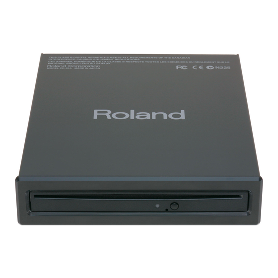
CD-01A Owner's Manual
USB CD Drive
Thank you, and congratulations on your choice of the Roland CD-01A USB CD Drive.
The CD-01A is a CD drive designed to be used exclusively with Roland products. It should not be used with
personal computers or equipment produced by other manufacturers.
Before using this unit, carefully read the sections entitled: "USING THE UNIT SAFELY" and "IMPORTANT
NOTES" (other side). These sections provide important information concerning the proper operation of
the unit. Additionally, in order to feel assured that you have gained a good grasp of every feature
provided by your new unit, Owner's Manual should be read in its entirety. The manual should be saved
and kept on hand as a convenient reference.
Copyright © 2008 ROLAND CORPORATION
All rights reserved. No part of this publication may be reproduced in any form without the written
permission of ROLAND CORPORATION.
Panel Descriptions and Contents of the Package
CD Drive Unit
Front Panel
Disc Slot
Eject Button
Access Lamp
AC adaptor
Power Cord
Mounting
Plate (2 pcs.)
* Depending on the circumstances of a particular setup, you may experience a discomforting sensation, or perceive that the
surface feels gritty to the touch when you touch this device. This is due to an infinitesimal electrical charge, which is
absolutely harmless. However, if you are concerned about this, connect the ground terminal (see figure) with an external
ground. When the unit is grounded, a slight hum may occur, depending on the particulars of your installation. If you are
unsure of the connection method, contact the nearest Roland Service Center, or an authorized Roland distributor, as listed
on the "Information."
Unsuitable places for connection
• Water pipes (may result in shock or electrocution)
• Gas pipes (may result in fire or explosion)
• Telephone-line ground or lightning rod (may be dangerous in the event of lightning)
Connecting to the Equipment
* To prevent malfunction and/or damage to speakers or other devices, always turn down the volume, and turn off the power
on all devices before making any connections.
* When connecting the CD-01A, be sure to read the connection instructions and cautions on connection in the owner's
manual for the equipment to which you're connecting the CD-01A.
USB Cable
To prevent the inadvertent disruption of power to
your unit (should the plug be pulled out
accidentally), and to avoid applying undue stress
to the AC adaptor jack, anchor the power cord
using the cord hook, as shown in the illustration.
Switching On the Power
* Once the connections have been completed, turn on power to your various devices in the order specified. By turning on
devices in the wrong order, you risk causing malfunction devices.
1.
Set the power switch to "AUTO."
2.
Switch on the power to the equipment you're using.
The CD-01A is interlinked with the equipment's power, and
comes on automatically when the equipment is switched on.
* Depending on the equipment that the CD-01A is connected to, the power to it may not be switched on automatically. In
such cases, manually set the CD-01A's power switch to the "ON" position.
Inserting and Ejecting Discs
When inserting a disc, make sure the CD-01A is powered up, and
gently insert the disc into the disc slot. Once the disc has been
inserted a certain distance, it is automatically pulled the rest of the
way into the drive.
To take out the disc, press the Eject button.
* This unit cannot use discs of nonstandard shape.
* If pressing the Eject button fails to eject the disc, do not try using force
to remove it. Instead, contact the nearest Roland Service Center, or an
authorized Roland distributor, as listed on the "Information."
Installing on the Equipment
1.
Attach the mounting plates to the drive unit.
* Attachment requires a Phillips screwdriver. You will need to provide this yourself.
2.
Install the CD-01A on the equipment.
Check the model name of the equipment you're using.
*
5
1
0
0
0
0
3
2
7
4
-
Rear Panel
AC Adaptor Jack
Cord Hook
USB Connector
Power Switch
Ground Terminal
Security Slot ( )
http://www.kensington.com/
USB cable
Screw
Screw
(3 x 8 mm: 4 pcs.)
(4 x 16 mm: 4 pcs.)
(full-size drawing)
To the USB Connector on the Equipment
To the AC Outlet
Power cord
Place the AC adaptor so the side with
the indicator (see illustration) faces
AC Adaptor
upwards and the side with textual
information faces downwards.
The indicator will light when you plug
the AC adaptor into an AC outlet.
Screw
(3 x 8 mm)
0
1
*
Compatible Models and Installation Locations
Compatible
model name
Installation
location
* Installation on equipment not in the list of compatible models is not possible.
* Above table shows compatibility as of Oct. 2008. The latest information is listed for you on our website.
http://www.roland.com/
Installation Method A
3.
Using the included screws, install the drive unit in
the mounting holes (4 locations) on the underside of
the equipment.
4.
Connect the USB cable for the CD drive to the USB
connector for CD-drive connection on the
equipment.
* Before you make the connection, be sure to read the documentation for
the equipment to which you're connecting.
Installation Method B
3.
Using a Phillips screwdriver, remove the
rubber foot on the left side and toward the
front on the underside of the equipment
(full-size drawing)
where you're installing this unit.
4.
Detach the headphones hook and reattach
it at the location shown in the figure.
5.
Using the included screws, install the drive
unit in the mounting holes (2 locations) on
the underside of the equipment.
* Carefully store the removed screws and rubber foot in a
safe place out of the reach of small children, so there is no
chance of them being swallowed accidentally.
6.
Connect the USB cable for the CD drive to
the USB connector for CD-drive connection on the equipment.
* Before you make the connection, be sure to read the documentation for the equipment to which you're connecting.
RADIO FREQUENCY INTERFERENCE STATEMENT
This equipment has been tested and found to comply with the limits for a Class B digital device, pursuant to Part 15 of the
FCC Rules. These limits are designed to provide reasonable protection against harmful interference in a residential
installation. This equipment generates, uses, and can radiate radio frequency energy and, if not installed and used in
accordance with the instructions, may cause harmful interference to radio communications. However, there is no guarantee
that interference will not occur in a particular installation. If this equipment does cause harmful interference to radio or
television reception, which can be determined by turning the equipment off and on, the user is encouraged to try to correct the
interference by one or more of the following measures:
– Reorient or relocate the receiving antenna.
– Increase the separation between the equipment and receiver.
– Connect the equipment into an outlet on a circuit different from that to which the receiver is connected.
– Consult the dealer or an experienced radio/TV technician for help.
This device complies with Part 15 of the FCC Rules. Operation is subject to the following two conditions:
(1) this device may not cause harmful interference, and
(2) this device must accept any interference received, including interference that may cause undesired operation.
Unauthorized changes or modification to this system can void the users authority to operate this equipment.
This equipment requires shielded interface cables in order to meet FCC class B Limit.
This Class B digital apparatus meets all requirements of the Canadian Interference-Causing Equipment Regulations.
Power Switch
Cet appareil numérique de la classe B respecte toutes les exigences du Règlement sur le matériel brouilleur du Canada.
This product contains chemicals known to cause cancer, birth defects and other reproductive harm, including lead.
For EU Countries
DP-990, HPi-7S, HPi-6S, HP207, HP203, RG-3,
RG-1, RK-300, AT-900, AT-900C, AT-800,
AT-500, AT-300, AT-100, AT-75
Install on the right side. Install as described in
Install on the left side. Install as described in
"Installation Method A."
"Installation Method B."
3. Rubber Foot
This product complies with the requirements of EMC Directive 2004/108/EC.
FEDERAL COMMUNICATIONS COMMISSION
NOTICE
AVIS
WARNING
FP-7
Screw
(4 x 16 mm)
4.
Headphones
Hook
Screw (4 x 16 mm)
For EU Countries
For the USA
For Canada
For C.A. US (Proposition 65)
Advertisement

Related Manuals for Roland CD-01A

Summary of Contents for Roland CD-01A
-
Page 1: Federal Communications Commission
Cet appareil numérique de la classe B respecte toutes les exigences du Règlement sur le matériel brouilleur du Canada. * Depending on the equipment that the CD-01A is connected to, the power to it may not be switched on automatically. In such cases, manually set the CD-01A’s power switch to the “ON”... -
Page 2: Power Supply
Information could result in damage, malfunction, or to wipe all dust and other accumulations When you need repair service, call your nearest Roland Service Center or authorized Roland electric shock. distributor in your country as shown below. away from its prongs. Also, disconnect the ....................