Williams 5001922 Owner's Manual
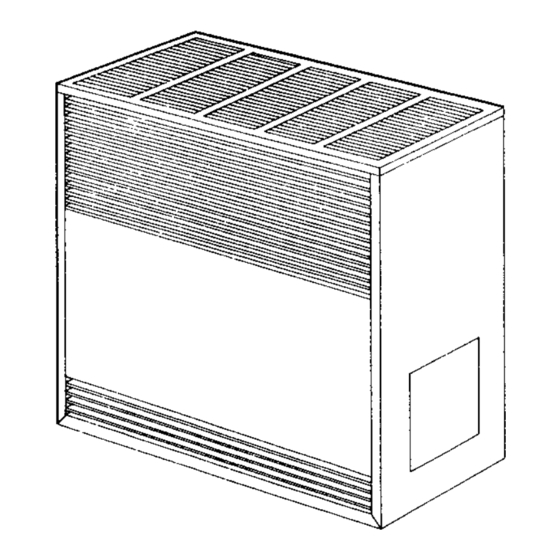
Vented room heater
Hide thumbs
Also See for 5001922:
- Brochure & specs (3 pages) ,
- Installation & operating instruction manual (20 pages)
Advertisement
MODEL
NOS:
FOR NAT. GAS ONLY
2001612;
2001622
3501512;
3501522
3501912;
3501922
5001512;
5001522
5001912;
5001922
6501512;
6501522
6501912;
6501922
MODEL
NOS.
FOR L.R GAS ONLY
2001611
2001621
3501511
3501521
3501911
3501921
5001511;
5001521
5001911;
5001921
6501511;
6501521
6501911;
6501921
INSTALLATION
& OPERATING
INSTRUCTION
MANUAL
350 MODEL SERIES SHOWN
READ THIS OWNERS
MANUAL
CAREFULLY
BEFORE YOU INSTALL
YOUR NEW WILLIAMS
VENTED
ROOM HEATER
WARNING:
Improper
installation,
adjust-
ment, alteration,
service
or maintenance
can
cause
injury
or property
damage.
Refer to this manual.
For assistance
or
additional
information
consult a qualified
Installer,
service
agency
or
the
gas
supplier.
WARNING:
Do not install any of these fur-
naces
(Natural
or L.P.
Gas)
in mobile
homes, trailers,
or recreational
vehicles.
WARNING:
If the information in this l
manual is not followed exactly, a fire or ex-
I
plosion may result causing property
damage, personal injury or loss of life.
--
Do notstore or use gasolineor other flam-
mable vapors and liquids in the vicinity
of this or any other appliance.
-- WHAT TO DO IF YOU SMELL GAS
• Open all windows.
• Do not try to light any appliance.
• Do not touch any electrical switch; do
not use any phone in your building.
• Extinguish any open flame.
• Immediately call your gas supplierfrom
a neighbor's phone. Follow the gas
supplier's instruction.
• If you cannot reach your gas supplier,
call the fire department.
--
Installation and service must be per-
formed by a qualified installer, service
agency or the gas supplier.
WILLIAMS
Furnace Co., 225 Acacia St., Colton, CA 92324
PRINTED IN USA 4/98
P500407
Advertisement
Table of Contents

Related Manuals for Williams 5001922


Summary of Contents for Williams 5001922
- Page 1 6501522 6501912; 6501922 350 MODEL SERIES SHOWN READ THIS OWNERS MANUAL MODEL NOS. FOR L.R GAS ONLY CAREFULLY BEFORE YOU INSTALL 2001611 2001621 YOUR NEW WILLIAMS 3501511 3501521 3501911 3501921 VENTED ROOM HEATER 5001511; 5001521 5001911; 5001921 6501511; 6501521 6501911;...
-
Page 2: Limited Warranty
LIMITED WARRANTY The Manufacturer, Williams Furnace Co., warrants this wall furnace or heater to the original purcheser under the following conditions: LIMITED ONE-YEAR WARRANTY 1. Any part thereof which proves to be defective in material or workmanship within one year from date of odginal purchase for use will be repaired or replaced at the Manufacturer's option, FOB its factory. - Page 3 This was done to assure you of receiving the best value and most reliable appliance of its type available today. We are confident that your Williams furnace can provide you years of low cost, efficient, heating comfort. Thank you for purchasing a Williams furnace.
- Page 4 Safety Rules WARNING. umn. The maximum inlet gas supply pressure is 13" water column. READ THESE RULES AND THE INSTRUCTIONS CAREFULLY. FAILURE FOLLOW THESE ANY SAFETY SCREEN, GUARD OR PARTS RE- RULES AND INSTRUCTIONS COULD CAUSE A MOVED FOR SERVICING FROM THIS APPLIANCE MALFUNCTION OF THE FURNACE.
- Page 5 The manifoldpressure ,shouldbe 10.5 inches water column for L.P. Gas. Orifice change may be required to suit gas supplied. Check with your WILLIAMS service department. FOr heater located at elevations between sea level and 2000 feet, the measured input must not be greater than the input shown on the rating plate of the heater.
-
Page 6: Installation
PIPING THE GAS TO THE HEATER State and local authorities have established codes regulating the installation of gas burning equipment. Consult your gas supplier or gas company for complete information. In the absence of local codes, all aspects of the installation must comply with the national fuel gas coda ANSI Z223.1. - Page 7 WARNING .WARNING DANGER OF ILLNESS DANGER OF PROPERTY DAMAGE, BODILY INJURY OR DEATH BODILY INJURY OR DEATH EVEN WHEN HOUSE MEETS REQUIREMENTS THE FURNACE AND ANY OTHER FUEL BURNING FOR UNCONVINED SPACE WITH ADEQUATE AIR APPLIANCE MUST BE PROVIDED WITH ENOUGH INFILTRATION IT IS RECOMMENDED THAT A FRESH AIR FOR PROPER COMBUSTION...
-
Page 8: Mounting The Thermostat
6 inches of cable protrubes. ERATION. VERIFY PROPER OPERATION AFTER SERVICING. 7. Route cable to heater. THERMOSTAT GENERATOR GENERATOR THERMOSTAT LIMIT SWITCH €--- WHITE BLUE KNOB GREEN KNOll WILLIAMS WILLIAMS P295000A (OR} P172100A (OR) P295001A LIMIT SWITCH P172200A Fig. 4 --8--... - Page 9 Any major changes in the flow must be made adjustment is needed, see page 14. by changing the size of the bumer orifice. Check with your WILLIAMS service department for proper orifice sizing. CHECK THERMOSTAT 1/2 TO5/s Check thermostat operation. When set above temperature...
-
Page 10: Gas Control
FOR YOUR SAFETY, READ BEFORE LIGHTING WILLIAMS GAS CONTROL VALVE P322051 (OR) P322052 (OR) P500419 (OR) P5004_,0 r WARNING: If you do not follow these instructions exactly, a fire or explosion may result causing property damage, personal injury or loss of life,... -
Page 11: To Turn Off Gas To Appliance
m ..u,t c .us,., or,o. o,,i. • If you cannot reach your gas supplier, call the fire This appliance has a pilot which must be lighted department. hand. When lighting the pilot, follow these instructions exactly. Use only your hand to push In or turn the gas control knob. - Page 12 FOR YOUR SAFETY, READ BEFORE LIGHTING WILLIAMS GAS CONTROL VALVE P172100A & P172200A WARNING: If you do not follow these instructions exactly, a fire or explosion may result causing property damage, personal injury or loss of life. • It you cannot...
- Page 13 WARNING: If you do not follow these instructions exactly, a fire or explosion may result causing property damage, personal injury or loss of life. • If you cannot reach your gas supplier, call the fire This appliance has a pilot which must be Ughted department.
-
Page 14: Top View
How To Care For Your Heater CLEANING BURNER COMPARTMENT CABINET FINISH Clean cabinet with damp rag. Never use abrasive cleaners. Because cold air is attracted to the flame during furnace Cabinets are finished with heat resistant baked enamel operation, a build up of lint from bedding and dust (etc.) -- DO NOT refinish with wall paint. - Page 15 INSTALLATION & OPERATING INSTRUCTION 2101 BLOWER ACCESSORY (AVAILABLE ONLY 350, 500, & 650 MODEL SERIES) WARNING NOTE:All electrical work must be conform to your local codes and ordinances or in their absence, with OR DEATH. ] URN OFF ElECTRiCAL P OWER SUPPLY National Electrical Code,ANSI/NFPA...
- Page 16 & OPERATING INSTALLATION INSTRUCTION (con't) 21 01 BLOWER ACCESSORY STEP Remove temperature dial from control valve discard. Install coupling control valve secure by tightening screw. Slide previously assembled control down through control insert into coupling attached control valve. Secure couplincj with cotter pin.
-
Page 17: Parts List
INSTALLATION & OPERATING INSTRUCTION 2101 BLOWER ACCESSORY - REPLACEMENT PARTS (350, 500, &: 650 MODEL SERIES ONLY) NO._._ ITEMS 5,6,7, & 16 ARE NOT SUPPUED OR REQUIRED Y, I IH WAll TYPE THERMOSTAT MODELS REPLACEMENT PARTS LIST - MANUFACTURES AUTHORIZED PARTS) (USE ONLY... - Page 18 WILLIAMS GAS FIRED ROOM HEATER REPLACEMENT PARTS 20016 MODEL SERIES • .j" j" FOR PARTS UST SEE PAGE 19 USE ONLY MANUFACTURER'S AUTHORIZED PARTS --18---...
- Page 19 REPLACEMENT PARTS FOR MODELS 2001611 2001612 2001621 2001622 !KE'_ DESCRIPTION 2001611 2001612 2001621 2001622 WRAPPER ASSEMBLY K000275 K000275 K000275 K000275 DRAFT DIVERTER ASSY. K000274 K000274 K000274 K000274 COMBUSTION CHAMBER KOOO27g K000279 K000279 K000279 ASSEMBLY BASE PLATE K000265 K000265 K000265 K000265 VALVE BRACKET K000266 K000266...
- Page 20 WILLIAMS GAS FIRED ROOM HEATER REPLACEMENT PARTS 350, 500, & MODEL SERIES FOR PARTS LISTING (ENCLOSED CONSOLES) SEE PAGE 21 (OR) USE ONLY MANUFACTURERS ./_-.,._ NOTE: AUTHORIZED PARTS ITEMS 24 AND 18 ARI_ NOT USED OR SUPPLIED WITH WALL THERMOSTAT MODELS >...
- Page 21 ENCLOSED CONSOLES REPLACEMENT PARTS FOR BUILT-IN THERMOSTAT MODELS 3501512 3501511 5001512 5001511 6501512 6501511 3501912 3501911 5001912 5001911 6501912 6501911 <EY DF_..SCRIP'IION 3501512 3501511 5001512 5001511 6501512 6501511 _10. 3501912 3501911 5001912 5001911 6501912 6501911 PANEL SIDE (R.H.) K000204 K000204- K000205 KC00205 K000206...
- Page 22 ENCLOSED CONSOLES REPLACEMENT PARTS FOR WALL THERMOSTAT MODELS 3501522 3501521 5001522 5001521 6501522 6501521 3501922 3501921 5001922 5001921 6501922 6501921 DESCRIP'IION 3501522 3501521 5001522 5001521 6501522 6501521 3501922 3501921 5001922 5001921 6501922 6501921 PANEL SIDE (R.H.) K000204 K000204 K000205 K000205 K000206 K000206 2 ' THERMOSTAT...
-
Page 23: For Your Safety
1. MODEL NUMBER The Model Number of your Williams room heater will be 2. MFG. DATE CODE found on the rating plate near gas valve, inside control 3, PART NUMBER compartment.