Edimax EW-7428HCn User Manual
N300 high power ceiling mount wireless poe range extender/access point
Hide thumbs
Also See for EW-7428HCn:
- Quick installation manual (16 pages) ,
- Specifications (3 pages) ,
- User manual (78 pages)
Table of Contents
Advertisement
Quick Links
Advertisement
Table of Contents

Related Manuals for Edimax EW-7428HCn


Summary of Contents for Edimax EW-7428HCn
- Page 1 EW-7428HCn User Manual 08-2012 / v1.0...
- Page 2 COPYRIGHT Copyright Edimax Technology Co., Ltd. all rights reserved. No part of this publication may be reproduced, transmitted, transcribed, stored in a retrieval system, or translated into any language or computer language, in any form or by any means, electronic, mechanical, magnetic, optical, chemical, manual or otherwise, without the prior written permission from Edimax Technology Co., Ltd.
-
Page 3: Table Of Contents
CONTENTS PRODUCT INFORMATION..................5 I-1. Package Contents .................... 5 I-2. Physical Description ..................5 I-3. Front Panel ...................... 5 I-4. Back Panel ....................... 6 I-5. Safety Information ................... 7 I-6. System Requirements ..................8 I-7. Hardware Installation ..................8 I-7-I. Connecting the Access Point to a Router or PoE Switch ...... - Page 4 IV-1-4. Mac OS ....................82 IV-2. Troubleshooting ................... 86 IV-3. Glossary ......................88...
-
Page 5: Product Information
I. PRODUCT INFORMATION Thank you for purchasing the Edimax EW-7428HCn N300 High Power Ceiling Mount Wireless PoE Range Extender/Access Point! This device is an ideal choice for users looking to expand their home or office networking environment. Its easy installation procedure also allows any computer user to set up a network environment in a matter of minutes. -
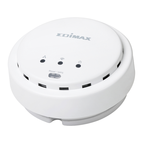
Page 6: Back Panel
Flashing Device is resetting to factory default settings. WPS is activated and the device is waiting for a WPS signal from another device. Flashing Wi-Fi activity (transferring data). (2)Wi-Fi Connected to a local area network. Not connected to a local area network. (3)LAN Flashing LAN activity (transferring data). -
Page 7: Safety Information
I-5. Safety Information In order to ensure the safe operation of the device and its users, please read and act in accordance with the following safety instructions. 1. The access point is designed for indoor use only; do not place the access point outdoors. -
Page 8: System Requirements
I-6. System Requirements - Computer or network device with wired or wireless network interface card. - Web browser (Microsoft Internet Explorer 7.0 or above, Opera web browser, or Safari web browser). - Available AC power socket (100 – 240 V, 50/60Hz) or 802.3af Power Over Ethernet (PoE) Switch. - Page 9 3. If you are using a router then plug the power adapter into a wall socket, and connect it to the 5V DC power port on the access point. Reattach the back panel cover, twisting it clockwise to secure it into place. 4.
-
Page 10: Fixing The Access Point To A Ceiling
I-7-2. Fixing the Access Point to a Ceiling 1. To attach the device to the ceiling in its final location, attach the device’s back panel to the ceiling with the included screws (mounting kit). Then, attach the rest of the device to the back panel, twisting it clockwise to lock it into place. -
Page 11: Ii. Getting Started
II. GETTING STARTED 1. Carefully remove the back panel cover by twisting it counter-clockwise. This enables easier access to the LAN port and the power adapter. 2. Plug one end of an Ethernet cable into the device’s Ethernet port, plug the other end into your computer’s Ethernet port. - Page 12 Note: The URL on your card will likely differ from the example shown in this guide. Please enter the URL you see on your card, and not the URL used in the examples here. 6. Open a web browser, such as Internet Explorer. Enter the access key into the browser URL bar.
- Page 13 <Windows PC> <Mac PC> 8. You will then enter the iQ Setup screen, where you can choose which mode to activate. The default mode for the device is Access Point Mode. 1. For Access Point Mode, please see section II-1. Access Point Mode 2.
-
Page 14: Ii-1. Access Point Mode
Wi-Fi password, select ‘Enabled’ from the drop-down menu and enter your desired password in the ‘Wi-Fi Network Password field’. Otherwise, if you keep the default settings, the device’s wireless network will have the default ID of ‘Edimax’ and will use no password. - Page 15 Note: If the device is not set to “Obtain an IP address automatically”, then please select that option by clicking on the radio button circled in the above image. 4. Click ‘APPLY’ when you are done. You will see a confirmation screen, with your Wi-Fi settings.
-
Page 16: Ii-2. Universal Wi-Fi Extender Mode
7. You may now connect to the device wirelessly by selecting its ID from your list of Wi-Fi networks, and entering the password you set (if you set one). II-2. Universal Wi-Fi Extender Mode Universal Wi-Fi Extender Mode allows you to extend the range of an existing Wi-Fi network;... - Page 17 network. 3. By default, the device’s SSID is the root access point’s SSID plus the last six characters of the device’s access key. You can change the device’s SSID if you want. Click “Next” to complete the setup. 4. The device will test the connection between itself and the root wireless access point.
- Page 18 7. You may test the connectivity of the device by disconnecting the Ethernet cable from your computer’s Ethernet port, and then attempting to connect to the device wirelessly (select its SSID from your list of wireless networks, not the SSID of your root Wi-Fi access point). Then, attempt to open a web page with your web browser.
-
Page 19: Ii-3. Wireless Client Mode
II-3. Wireless Client Mode Wireless Client Mode allows Ethernet devices such as smart televisions and video game consoles to connect to a wireless access point. 1. Select Wireless Client Mode from the list. iQ Setup will start detecting available Wi-Fi networks automatically. All detected Wi-Fi networks will be displayed in the list. - Page 20 If the connection is successful, the message “Connection Successfully” will appear on-screen. Click “Next” to save settings. If the connection failed, the message “Connection Test Failed” will appear on-screen. Click “Back” to restart the setup process. 4. The device will show a brief summary of the name of the root wireless access point, the name of the device, and the security type used.
-
Page 21: Iii. Browser Based Configuration Interface
URL you see on your card, and not the URL used in the examples here. Open a web browser, such as Internet Explorer. Enter the access key (http://edimax******) or default IP address into the browser URL bar. (Windows PCs only) - Page 22 For Mac users, enter the default IP address (http://192.168.2.2) into your browser’s address bar. (MacOS and Linux) Note: The access point uses the default IP address 192.168.2.2, which may not be in the same IP address subnet of your network. Accordingly, you may need to modify the IP address of your PC or Macintosh to 192.168.2.10, before you can access the browser-based configuration interface.
-
Page 23: Iii-1. Home
<Windows PC> <Mac PC> Options are listed in the sidebar on the left side of the interface. III-1. Home The Home page shows the basic status and information of the device. - Page 24 Note: This screenshot is an example. The information you see on your screen will likely differ from this screenshot. Uptime Displays the total passed time since the device was turned on Hardware Displays the hardware version. This Version information is helpful when you need online help from the dealer of purchase.
-
Page 25: Iii-2. Iq Setup
Number number Security Displays the current wireless security setting BSSID (MAC) Displays the device’s MAC address. A MAC address is a unique identifier for this device, it cannot be modified by users) Associated Displays the number of connected wireless Clients client Show Active Displays a list of connected devices, along... -
Page 26: Iii-3. Basic Setting
III-3. Basic Setting This device can be set to operate in different modes. You can select the mode you want by selecting Basic Setting from the sidebar. - Page 27 You can select a mode of operation from the drop-down menu. There are six modes available: Access point mode, allows wireless clients to connect to this device and exchange data with the devices connected to the wired network. Station-Infrastructure Also known as wireless client mode. Enables Ethernet-only devices such as smart TVs and game consoles to connect to a wireless network...
-
Page 28: Iii-3-1. Ap Mode
same mode, and links any wired networks connected to these two wireless access points together. Only one access point can be connected in this mode. AP Bridge-Point to Establishes a wireless connection with other Multi-Point wireless access points using the same mode, and links any wired networks connected to these wireless access points together. - Page 29 Band Please select the wireless band you wish to use. By selecting different band settings, you’ll be able to allow or deny wireless clients using certain bands. If you select 2.4GHz (B), 2.4GHz (N), or 2.4GHz (G), only wireless clients using the wireless band you select (802.11b, 802.11n, or 802.11g) will be able to connect to this access point.
- Page 30 access point’s SSIDs. You can input a numeric VLAD ID value between 1 – 4094 for the MAIN ESSID. Channel Please select a channel number you wish to Number use. If you know a certain channel number is being used by other wireless access points nearby, please refrain from using the same channel number Associated...
- Page 31 Displayed here is the number of each additional ESSID. Enable Check the box to enable or disable a specific ESSID accordingly. SSID Please input the ESSID (the name used to identify this wireless access point) here. You can input up to 32 alphanumerical characters.
- Page 32 you’ll be able to allow or deny wireless clients using certain bands. If you select 2.4GHz (B), 2.4GHz (N), or 2.4GHz (G), only wireless clients using the wireless band you select (802.11b, 802.11n, or 802.11g) will be able to connect to this access point.
-
Page 33: Iii-3-2. Station-Infrastructure Mode
III-3-2. Station-Infrastructure Mode When in Station-Infrastructure mode, the device acts as a wireless client, and can be connected to Ethernet-only Internet devices, such as smart televisions or video game consoles. This gives these devices the capability to connect to the Internet wirelessly. Band Please select the wireless band you wish to use. - Page 34 Site Survey When you use this device to give an Ethernet network device wireless capability, you have to associate it with a working access point. Click the “Select Site Survey” button, and a “Wireless Site Survey Table” will pop up. It will list all available access points nearby.
-
Page 35: Iii-3-3. Ap Bridge-Point To Point Mode
its SSID, in which case you will need to manually enter the SSID in the “MAIN SSID” field on the previous page. III-3-3. AP Bridge-Point to Point Mode In this mode, the access point connects to another wireless access point in the same mode, and all connected Ethernet clients of both devices will be connected together. -
Page 36: Iii-3-4. Ap Bridge-Point To Multi-Point Mode
Number to use. The channel number must be same as the other wireless access point you wish to connect to. MAC address 1 Please input the MAC address of the wireless access point you wish to connect Set Security Click this button to select an encryption mode for this wireless link. - Page 37 Band Please select the wireless band you wish to use. By selecting different band settings, you’ll be able to allow or deny access points using certain bands. If you select 2.4GHz (B), 2.4GHz (N), or 2.4GHz (G), only access points using the wireless band you select (802.11b, 802.11n, or 802.11g) will be able to connect to this device.
-
Page 38: Iii-3-5. Ap Bridge-Wds
with security options will appear. Click “APPLY” to make changes take effect. The following message will appear: Click “CONTINUE” to save the changes but not apply them yet. This allows you to make further changes in the browser-based management interface, before applying them all at once. - Page 39 Band Please select the wireless band you wish to use. By selecting different band settings, you’ll be able to allow or deny devices using certain bands. If you select 2.4GHz (B), 2.4GHz (N), or 2.4GHz (G), only devices using the wireless band you select (802.11b, 802.11n, or 802.11g) will be able to connect to this device.
- Page 40 access point’s SSIDs. You can input a numeric VLAD ID value between 1 – 4094 for the MAIN ESSID. Channel Please select a channel number you wish to Number use. The channel number must be same as the other wireless access points you wish to connect to.
- Page 41 multiple ESSID’s. Note: The security settings for multiple ESSID’s can be configured from the Security screen. Please see III-5-1. Security for more information. Displayed here is the number of each additional ESSID. Enable Check the box to enable or disable a specific ESSID accordingly.
- Page 42 kinds of data, to give higher priority to applications which require instant responses. This improves the performance of such network applications. Band Please select the wireless band you wish to use. By selecting different band settings, you’ll be able to allow or deny wireless clients using certain bands.
-
Page 43: Iii-3-6. Universal Repeater Mode
Click “OK” to return to the “Basic Setting” screen. III-3-6. Universal Repeater Mode In this mode, this device acts as a wireless extender, simultaneously performing the functions of a client and an access point. It can extend the wireless signal of an access point, thus expanding Wi-Fi coverage and eliminating dead spots. - Page 44 If you select 2.4GHz (B+G), then only devices using the 802.11b and 802.11g bands will be able to connect to this device. If you want to allow 802.11b, 802.11g, and 802.11n devices to connect to this device, select 2.4GHz (B+G+N). MAIN SSID Please input the ESSID (the name used to identify this wireless access point) here.
- Page 45 act as a station and connect to a root AP. Enter the SSID of the root AP here, or click the “Select Site Survey” button to choose a root AP. Select Site Click the “Select Site Survey” button, and a Survey “Wireless Site Survey Table”...
- Page 46 SSID” field on the previous page. Multiple ESSID When you click the “Multiple ESSID” button, a new window will open, as shown below. This page allows you to configure the wireless settings for multiple ESSID’s. Note: The security settings for multiple ESSID’s can be configured from the Security screen.
- Page 47 WMM (Wi-Fi Multimedia) technology can improve the performance of certain network applications, such as audio/video streaming, network telephony (VoIP), and others. When you enable WMM, the access point will define the priority of different kinds of data, to give higher priority to applications which require instant responses.
-
Page 48: Iii-4. Wps Setting
access point’s SSIDs. You can input a numeric VLAD ID value between 1 – 4094 for each specific ESSID. Click “APPLY” to make changes take effect. The following message will appear: Click “OK” to return to the “Basic Setting” screen. III-4. - Page 49 Enable WPS Check this box to enable or disable WPS Wi-Fi Protected All information related to WPS will be Setup displayed here. Information WPS Status Displays WPS status. If data encryption settings for this access point have never been set, “unConfigured” will be shown here.
- Page 50 Passphrase Key Shows the WPA passphrase here, though all characters will be replaced by asterisks for security reasons. If encryption is not set on this access point, this field will be blank. Device Configuration options for the device’s WPS Configuration settings can be found here.
-
Page 51: Iii-5. Wireless Advanced
III-5. Wireless Advanced This device has many advanced wireless features, which can be found in the Wireless Advanced menu. Note: The settings in the Wireless Advanced menu are for experienced users only. Please do not change the settings in this menu unless you are sure what they do. - Page 52 Fragment Set the Fragment threshold of the wireless Threshold radio. Please do not modify the default value if you don’t know what this does, the default value is 2346 RTS Threshold Set the RTS threshold of the wireless radio. Please do not modify the default value if you don’t know what this does, the default value is 2347 Beacon Interval...
-
Page 53: Iii-5-1. Security
connect to it. WMM (Wi-Fi Multimedia) technology can improve the performance of certain network applications, such as audio/video streaming, network telephony (VoIP), and others. When you enable WMM, the access point will define the priority of different kinds of data, to give higher priority to applications which require instant responses. - Page 54 encryption). When the data is encrypted, information transmitted wirelessly cannot be read by anyone who does not know the correct encryption key. Note: It is very important to set up wireless security. Without security enabled, hackers or intruders may gain access to your local network and cause damage to your computers and servers.
- Page 55 WEP (Wired Equivalent Privacy) is a common encryption mode, it’s generally safe enough for home and personal use. But if you need a higher level of security, please consider using WPA encryption (see next section). However, some wireless clients don’t support WPA, but only support WEP, so WEP is still a good choice if you have such a client in your network environment.
- Page 56 format, you can use the characters 0-9, a-f, and A-F. You must enter at least one encryption key here, and if you entered multiple WEP keys, they should not be same as each other. Enable 802.1x Check this box to enable 802.1x user Authentication authentication.
- Page 57 WPA RADIUS is a combination of WPA encryption and RADIUS user authentication. If you have a RADIUS authentication server, you can check the identity of every wireless client by using a user database. WPA Unicast Available options are: WPA (TKIP), WPA2 Cipher Suite (AES), and WPA2 Mixed.
-
Page 58: Iii-5-2. Mac Filtering
Enable 802.1x Enable or disable the use of 802.1x user Authentication authentication. RADIUS Server Enter the IP address of the RADIUS IP Address authentication server here. RADIUS Server Enter the port number of the RADIUS Port authentication server here. Default value is 1812. - Page 59 Select SSID (1) Address filtering table (2) Add new entries here (3) (1) Select SSID: Here you select the SSID you wish to configure. (2) MAC Address Filtering Table: This table lists the MAC addresses you have currently added to the white list. (3) Here you enter the information for new MAC addresses to add to the white list.
-
Page 60: Iii-6. System Utility
Comment You can input any text here as the comment of this MAC address, such as “ROOM 2A Computer” or something else to identify the MAC address. You can enter up to 16 alphanumerical characters here. This is optional and you can leave it blank, however, it’s recommended to use this field to write a comment for every MAC addresses as a memory aid. -
Page 61: Iii-6-1. Administrator
“System Utility” consists of four main functions. The default screen you will see upon selecting “System Utility” is the “Administrator” screen. III-6-1. Administrator Password Settings You can change the password used to login to the browser-based configuration interface here. It is advised to do so for security purposes. Current Enter your current password. - Page 62 IP address to the access point. (Windows PCs only) Note: If you choose “Obtain an IP address automatically” then you will need to use the access key (http://edimax******) to access the browser-based configuration device. This is because the access point will act as a DHCP client and receive a dynamic IP from the DHCP server, i.e.
- Page 63 IP Address Specify an IP address here. This IP address will be assigned to your access point, and will replace the default IP address 192.168.2.2. Subnet Mask Input the subnet mask of the new IP address. Gateway Input the network’s gateway IP address. Address Typically, your ISP will provide you with such information as IP address, subnet mask and gateway address.
- Page 64 Click “CONTINUE” to save the changes but not apply them yet. This allows you to make further changes in the browser-based management interface, before applying them all at once. Click “APPLY” to restart the device and implement any changes. The device will restart itself.
-
Page 65: Iii-6-2. Time Setting
Click “APPLY” to make changes take effect. The following message will appear: Click “CONTINUE” to save the changes but not apply them yet. This allows you to make further changes in the browser-based management interface, before applying them all at once. Click “APPLY”... -
Page 66: Iii-6-3. Power Saving
Click “APPLY” to make changes take effect. The following message will appear: Click “CONTINUE” to save the changes but not apply them yet. This allows you to make further changes in the browser-based management interface, before applying them all at once. Click “APPLY”... -
Page 67: Iii-6-4. Scheduling Setting
Click “CONTINUE” to save the changes but not apply them yet. This allows you to make further changes in the browser-based management interface, before applying them all at once. Click “APPLY” to restart the device and implement any changes. The device will restart itself. - Page 68 Service Select the event to be scheduled from the drop down menu. “Wireless off” will disable the wireless capability of the access point, “Led off” will switch off the LEDs and “Auto reboot” will restart the device. Schedule Assign the event a name or description for Description reference (optional).
- Page 69 Delete Click “Delete” to delete the event permanently. Click “APPLY” to make changes take effect. The following message will appear: Click “CONTINUE” to save the changes but not apply them yet. This allows you to make further changes in the browser-based management interface, before applying them all at once.
-
Page 70: Iii-7. Configuration Tool
III-7. Configuration Tool The access point’s configuration tool enables you to back up the settings, upgrade the firmware and reset the device. Select “Configuration tool” from the sidebar. You will see the following screen: Backup Settings Click “Save” to save the current settings on your computer as config.bin file. - Page 71 password and click “Ok”. See below for more information. Note: Restoring settings to the factory default will restore all settings, configurations and passwords back to the factory default. Note: You can also reset the device to the factory default by pressing and holding the Reset/WPS button for 10 seconds, until the Power LED ( goes out.
-
Page 72: Iii-7-1. Diagnosis
III-7-1. Diagnosis Using the diagnosis tool, you can ping a specific IP address and automatically reboot the device if there is no response. Watchdog and Select “Enable” or “Disable” for the reboot device automatic reboot function. Ping Address Specify the IP address to ping. Time interval Specify the frequency of the ping as a time interval, in minutes. -
Page 73: Iii-7-2. Firmware Upgrade
Selecting “Firmware upgrade” from the “Configuration Tool” menu allows you to update the system firmware to a more recent version. You can download the latest firmware from the Edimax website. Note: Do not turn off or disconnect the access point during a firmware upgrade, as this could damage the device. -
Page 74: Iii-7-3. Reboot
III-7-3. Reboot If the access point malfunctions or is not responding, then it is recommended that you reboot the device. This is useful if the location of the access point is not convenient. Note: If the access point is still not responding after a system reboot, switch off the device by unplugging the power supply. -
Page 76: Appendix
APPENDIX IV-1. Configuring your IP address The access point uses the default IP address 192.168.2.2, which may not be in the same IP address subnet of your network; meaning you are unable to access the browser based configuration interface. In this case, you need to modify the IP address of your PC or Macintosh to 192.168.2.10, in order to access the browser-based configuration interface. -
Page 77: Iv-1-2. Windows Vista
2. Select “Use the following IP address”, then input the following values: IP address: 192.168.2.10 Subnet Mask: 255.255.255.0 Click ‘OK’ when finished. IV-1-2. Windows Vista 1. Click the “Start” button (it should be located in the lower-left corner of your computer), then click “Control Panel”. - Page 78 2. Select “Use the following IP address”, then input the following values: IP address: 192.168.2.10 Subnet Mask: 255.255.255.0 Click ‘OK’ when finished.
-
Page 79: Iv-1-3. Windows 7
IV-1-3. Windows 7 1. Click the “Start” button (it should be located in the lower-left corner of your computer). 2. Under “Network and Internet” click “View network status and tasks”. 3. Click “Local Area Connection”. - Page 80 4. Click “Properties”. 5. Select “Internet Protocol Version 4 (TCP/IPv6) and then click “Properties”.
- Page 81 6. Select “Use the following IP address”, then input the following values: IP address: 192.168.2.10 Subnet Mask: 255.255.255.0 Click ‘OK’ when finished.
- Page 82 IV-1-4. Mac OS 1. Have your Macintosh computer operate as usual, and click on “System Preferences” 2. In System Preferences, click on “Network”. 3. Here you will see all of your network connections. You need to remove any Ethernet cable that may be connected, so that the “Ethernet” status in the left sidebar displays “Not Connected”, as shown below.
- Page 83 5. Connect one end of an Ethernet cable to the Ethernet port on your computer. Connect the other end to an Ethernet port on the access point. 6. Plug the power adapter into the device’s 5V power port, and plug the adapter into a wall socket.
- Page 84 8. Click on “Ethernet” in the left panel and then click the drop down arrow for the menu labeled “Configure IPv4” in the right panel. From the drop down menu, select “Manually”. 9. In the panel on the right side, enter IP address 192.168.2.10 and subnet mask 255.255.255.0.
- Page 85 10. In the left sidebar, “Ethernet” should now display “Connected” as shown below. In the right panel, you should see the IP address 192.168.2.10 and subnet mask 255.255.255.0.
- Page 86 IV-2. Troubleshooting If you are experiencing problems with your access point, please refer to this troubleshooting guide before contacting your dealer of purchase for help. Scenario Solution I can’t log onto the a. Please check the connection of the browser-based power cord and network cable.
- Page 87 my wireless client. browser-based configuration interface) is “Enabled” or “Disabled”. If “Disabled” you need to input the ESSID into your wireless client manually. b. Try moving closer to the wireless access point. File downloads are a. Reset the access point. very slow or b.
- Page 88 IV-3. Glossary Default Gateway (Access point): Every non-access point IP device needs to configure a default gateway’s IP address. When the device sends out an IP packet, if the destination is not on the same network, the device has to send the packet to its default gateway, which will then send it out towards the destination.
- Page 89 separated by “.”: bbbbbbbb.bbbbbbbb.bbbbbbbb.bbbbbbbb, where each “b” can either be 0 or 1. A network mask is also a 32-bit binary pattern, and consists of consecutive leading 1’s followed by consecutive trailing 0’s, such as 11111111.11111111.11111111.00000000. Therefore sometimes a network mask can also be described simply as “x”...
- Page 90 Port: Network Clients (LAN PC) uses port numbers to distinguish one network application/protocol over another. Below is a list of common applications and protocol/port numbers: Application Protocol Port Number Telnet SMTP POP3 H.323 1720 SNMP SNMP Trap HTTP PPTP 1723 PC Anywhere TCP 5631 PC Anywhere UDP...
- Page 91 particular network (as opposed to valid IP address numbers recognized by the Internet, which must be assigned by InterNIC). TCP/IP, UDP: Transmission Control Protocol/Internet Protocol (TCP/IP) and Unreliable Datagram Protocol (UDP). TCP/IP is the standard protocol for data transmission over the Internet. Both TCP and UDP are transport layer protocol. TCP performs proper error detection and error recovery, and thus is reliable.