Table of Contents
Advertisement
Advertisement
Table of Contents

Related Manuals for Garmin GDL 69/69A


Summary of Contents for Garmin GDL 69/69A
-
Page 1: Installation Manual
GDL 69/69A Installation Manual 190-00355-02 June 2006 Revision E... - Page 2 This Page Intentionally Left Blank...
- Page 3 Garmin. Garmin hereby grants permission to download a single copy of this manual and of any revision to this manual onto a hard drive or other electronic storage medium to be viewed and...
- Page 4 This manual is written for software version 2.11, 2.13, 2.14, 3.00, 3.01, 3.02 or later. The software version and information in this document are subject to change without notice. Visit the Garmin web site (www.garmin.com) for current updates and supplemental information concerning the operation of this and other Garmin products.
-
Page 5: Table Of Contents
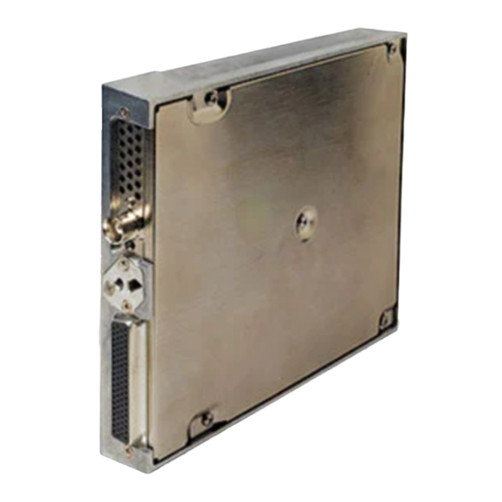
Cleaning ............................7-1 PPENDIX A - STC D ..........................A-1 PPENDIX NVIRONMENT UALIFICATION B - E ................B-1 PPENDIX ONSTRUCTION AND ALIDATION OF TRUCTURES C - C ............C-1 PPENDIX NSTALLATION RAWINGS D – I ....................D-1 GDL 69/69A Installation Manual Page v 190-00355-02 Revision E... - Page 6 LIST OF FIGURES Figure 1-1. GDL 69/69A Unit View ......................1-1 Figure 1-2. GDL 69/69A Remote Rack Unit Dimensions ............... 1-5 Figure 1-3. GDL 69/69A Modular Rack Unit Dimensions..............1-5 Figure 2-1. Suggested Mounting Locations for Remote Rack ..............2-2 Figure 2-2.
- Page 7 Table 1-1. Interfaced Equipment List....................... 1-2 Table 1-2. GDL 69/69A Specifications....................1-4 Table 1-3. GA 55, GA 55A, GA 57 Specifications.................. 1-4 Table 1-4. GDL 69/69A Unit Dimensions ....................1-4 Table 1-5. XM Antennas.......................... 1-6 Table 1-6. XM Satellite Radio Antenna Minimum Requirements............1-6 Table 1-7.
- Page 8 GDL 69/69A HARDWARE MOD LEVEL HISTORY The following table identifies hardware modification (Mod) Levels for the GDL 69/69A. Mod Levels are listed with the associated service bulletin number, service bulletin date, and the purpose of the modification. The table is current at the time of publication of this manual (see date on front cover) and is subject to change without notice.
-
Page 9: General Description
The information in this manual is STC approved. Only the equipment interfaces covered in this manual are within the scope of this STC. Other equipment may be suitable for use with the GDL 69/69A, but use of such equipment is beyond the scope of this STC – additional FAA approval may be required if equipment not covered in this manual is used to interface to the GDL 69/69A. -
Page 10: Interfaced Equipment
General Description 1.4 Interfaced Equipment Accomplishment of installation of the GDL 69/69A under this STC requires previous or concurrent installation of the following equipment. If installing the model GDL 69, a control display unit is required. If installing a GDL 69A, a control display unit and audio panel is required. -
Page 11: Xm Satellite Radio
The software is licensed solely for use within this product. 1.7 Interface Summary The following list is an interface summary for the GDL 69/69A units. Note that the GDL 69 does not have the audio interface. •... -
Page 12: Technical Specifications
General Description 1.8 Technical Specifications The GDL 69/69A and GA 55/GA55A XM antenna are PMA approved and there is no applicable TSO. The GA 57 GPS/WAAS – XM antenna is TSO authorized under TSO-c144. It is the responsibility of those desiring to install this equipment either on or within a specific type of class of aircraft to determine that the aircraft installation standards are within the prescribed standards. -
Page 13: Figure 1-2. Gdl 69/69A Remote Rack Unit Dimensions
0.49 [12.4] CENTER OF GRAVITY 8.74 [221.9] 1.60 0.37 4.46 [113.22] [40.53] [9.40] 0.73 [18.49] Figure 1-2. GDL 69/69A Remote Rack Unit Dimensions 1.23 31.1 WITH DIMPLES 1.20 30.5 WITHOUT DIMPLES 7.26 184.4 ANTENNA 6.30 160.0 6.90 175.3 3.00 76.2 J691 .60 15.2... -
Page 14: Table 1-5. Xm Antennas
GDL 69/69A. However, any equivalent XM antenna with specifications listed in Table 1-6 should work with the GDL 69/69A. Antennas must provide protection from direct lightning strikes. This STC does not support installations of equivalent antennas. -
Page 15: Reference Documents
1.12 Warranty Statement Limited Warranty This Garmin product is warranted to be free from defects in materials or workmanship for two years from the date of purchase. Within this period, Garmin will at its sole option, repair or replace any components that fail in normal use. - Page 16 Garmin retains the exclusive right to repair or replace the unit or software or offer a full refund of the purchase price at its sole discretion. SUCH REMEDY SHALL BE YOUR SOLE AND EXCLUSIVE REMEDY FOR ANY BREACH OF WARRANTY.
-
Page 17: Installation
This section provides hardware equipment information for installing the GDL 69/69A, cabling for the XM antenna (GA 55, GA 55A, or GA 57), and related hardware. Installation of the GDL 69/69A should follow the aircraft TC or STC requirements. For interconnects with the GDU 104x, MX20 MFD or 400/500 series refer to Appendix D of this manual. -
Page 18: Equipment Mounting
GDL 69/69A near sources that produce high levels of heat. The GDL 69/69A has two mounting rack options available, the remote rack and the modular rack for use with the G1000 system. -
Page 19: Figure 2-2. Gdl 69/69A Remote Mount Rack
1.86 pound unit (1.72 lbs. for GDL 69). If it is necessary to build a shelf or bracket to mount the GDL 69/69A rack or if is not certain that the chosen location is of sufficient structural integrity, refer to Appendix C. -
Page 20: Figure 2-3. Typical Rocker Switches
3. PART OF 011-00997-00 CONNECTOR KIT 4. APPLY THREAD LOCKING COMPOUND TO ALL THREADED FASTENERS. 115-00657-00 2 PLCS MAY ALTERNATELY USE P/N 115-00511-00 (PART OF KIT 011-01148-00) Figure 2-4. Modular Rack for the G1000 Page 2-4 GDL 69/69A Installation Manual Revision E 190-00355-02... -
Page 21: Cabling And Wiring
Appendix D. Verify the pin is properly engaged into the connector by gently tugging on the wire. Route and secure the cable run from the GDL 69/69A to the other units away from sources of electrical noise. -
Page 22: Table 2-3. Recommended Crimp Tools
M81969/1-04 NOTE 1. Insertion/extraction tools from ITT Cannon are all plastic; others are plastic with metal tip. 2. Non-Garmin part numbers shown are not maintained by Garmin and are subject to change without notice. 2.5.2 Connector Assembly 1. Backshell Cast Housing: Provides a mounting point for all other connector accessories. -
Page 23: Figure 2-5. Garmin Connector Assembly
Installation Procedure Table 2-4. Garmin Connector Assembly Item Number (Reference Garmin Part Description Figure 2-5) Number Backshell, with Config 50/78 Pin 125-00085-00 PCB Assembly, Configuration Module 012-00605-00 Connector, High Density, 78 Pin 330-00185-78 Wire Harness, Backshell Ground 320-00212-00 Clamp, Backshell, 62/78 Pin... -
Page 24: Figure 2-6. Backshell Assembly
Installation Procedure 2.5.3 Configuration Module Installation The GDL 69/69A connector kit includes one Garmin backshell assembly. The backshell assembly houses the configuration module. Garmin’s backshell also gives the installer the ability to easily terminate shield grounds at the backshell housing using the Spider grounding kit. Refer to Figure 2-6 for details and item numbers referenced below. -
Page 25: Table 2-5. Spider Kits
2-7. Table 2-6. Spider Installation Required Parts Reference Qty. Description Garmin Part Number/MIL Spec Figure 2-7 Included Cast Housing from Garmin Backshell Kit 011-00950-( ) 011-00980-00 2, 3, 4, 5 Spider Kit 011-00980-01 Shield Termination Parts used depend on method... -
Page 26: Figure 2-7. Spider Installation Drawing
(4) per shield. Remaining AWG #24 wires should be tied back and dressed with shrink tubing. 7. Wrap the cable bundle with Silicone Fusion Tape (Garmin P/N: 249-00114-00 or a similar version) at the point where the backshell strain relief (10) and cast housing (1) contacts the cable... - Page 27 P/N 62111281-0-0-N (62111231-0-0-N for the switch used for muting). Since the input signals are active-lo it is permissible to use multiple switches for each function. The would allow volume and channel control to be available at each passenger station. GDL 69/69A Installation Manual Page 2-11 190-00355-02...
-
Page 28: Xm Antenna
Installation Procedure 2.6 XM Antenna For use with the GDL 69/69A, the GA 55, GA 55A, and GA 57 antennas are an XM Satellite Radio antenna operating within a frequency range of 2332-2345 MHz for general aviation. NOTE Depending on specific installations, the installer may want to use a different make/model of XM Satellite Radio antenna. -
Page 29: Figure 2-8. Antenna Installation Location
Installation Procedure Figure 2-8. Antenna Installation Location GDL 69/69A Installation Manual Page 2-13 190-00355-02 Revision E... -
Page 30: Figure 2-9. Xm Signal Gain Requirements
The XM Radio Receiver used in the GDL 69/69A has a system signal requirement of 20dB +/- 1dB gain from the input of the antenna to the input of the XM receiver internal to the GDL 69/69A. To insure the... -
Page 31: Table 2-7. Xm Gain/Loss Component Calculation
Determining Antenna Cable Loss Value The GDL 69/69A is factory preset with a default cable loss value of 4.5 dB, which is equivalent to 12 to 16 feet of RG-400/U cable with two properly terminated TNC connectors. If the installed antenna cable is within this length, use this value in Table 2-7. - Page 32 Determining GDL 69/69A Gain/Loss Component Value The GDL 69/69A has a zero to 10dB variable attenuator that is used to balance the gain/loss component between its RF input and internal XM Receiver. The gain/loss components can be adjusted between +6dB and -4dB to balance the Antenna input to XM receiver 20dB gain requirement as specified for the XM system.
-
Page 33: Weight And Balance
Installation Procedure 2.7 Weight and Balance Weight and balance computation is required after the installation of the GDL 69/69A. Follow the guidelines as established in AC 43.13-1B, Chapter 10, Section 2. Make appropriate entries in the equipment list indicating items added, removed, or relocated along with the date accomplished. Include your name and certificate number in the aircraft records. -
Page 34: Cooling Air
Figure 2-10. TNC Connector Installation 2.9 Cooling Air The GDL 69/69A units do not require cooling air and do not generate an excessive amount of heat during typical operations; however the thermal characteristics of the installation should always be assessed. An undesirable thermal condition could be created due to the unit’s own internal power dissipation combined... -
Page 35: Figure 2-11. Gdl 69/69A Installation
Installation Procedure NOTE When inserting the GDL 69/69A into the Remote Mount Rack, it may be possible for the Pivot Pin (2) to fit between the unit and the mount rack without going into the slot of the Locking Plate (3). - Page 36 Installation Procedure This Page Intentionally Left Blank Page 2-20 GDL 69/69A Installation Manual Revision E 190-00355-02...
-
Page 37: System Interconnects
Ethernet In 2 A Ethernet Out 2 B Ethernet Out 2 A Ethernet In 3 B Ethernet In 3 A Ethernet Out 3 B Ethernet Out 3 A Spare Aircraft Power 1 GDL 69/69A Installation Manual Page 3-1 190-00355-02 Revision E... - Page 38 Volume Up (+) Volume Down (-) Signal Ground Spare Data Link Remote Power Off Power Ground Note 1: Line Out Audio is not supported in GDL 69A with software version prior to 3.00. Page 3-2 GDL 69/69A Installation Manual Revision E 190-00355-02...
-
Page 39: Functional Descriptions
The antenna cable connection is provided on a TNC coaxial connector. 3.2.1 Power The GDL 69/69A will accept input power from 9 to 33 VDC. The two aircraft power inputs (Aircraft Power 1, Aircraft Power 2) are intended to allow power to be provided by two different power busses. - Page 40 P691-32 Ethernet Receiver output Ch3-B P691-33 Ethernet Receiver output Ch3-A PORT 4 P691-56 Ethernet Receiver input Ch4-B P691-57 Ethernet Receiver input Ch4-A P691-58 Ethernet Receiver output Ch4-B P691-59 Ethernet Receiver output Ch4-A Page 3-4 GDL 69/69A Installation Manual Revision E 190-00355-02...
- Page 41 P691-17 Audio Out Lo. This is the common ground for the audio output P691-18 Audio Out Right. This is the right channel audio P691-19 Audio Out Left. This is the left channel audio GDL 69/69A Installation Manual Page 3-5 190-00355-02...
- Page 42 The following pins are spare pins and not connected inside the GDL 69/69A. Wires should not be routed to these pins as they may be used in future configurations of the GDL 69/69A. Use of these pins may result in unintended behavior.
-
Page 43: System Configuration/Checkout
The GDL 69/69A does not provide proper operation until the configuration initialization procedure is completed. 4.2.1 Configuration Module Procedure for Installation with MX20 Refer to the latest revision of the MX20 Installation Manual (Garmin AT Part Number 560-1025-( )) for instructions. GDL 69/69A Installation Manual... - Page 44 System Configuration/Checkout 4.2.2 Configuration Module Procedure for Installation with 400/500 Series Perform the following steps to program the configuration module of the GDL 69/69A when using the 400/500 Series as the control and display unit: 1. Power up the 400/500 in Configuration Mode (refer to the 400/500 Install Manual for instructions) 2.
-
Page 45: Configure Rs-232 Port
For installations with the MX20, refer to the MX20 Installation Manual for configuring the correct RS- 232 port of the MX20 that the GDL 69/69A is connected. For installations with the 400/500 series units, refer to the 400/500 Series Pilot’s Guide Addendum for configuring the correct RS-232 port of the 400/500 series unit that the GDL 69/69A is connected. -
Page 46: Figure 4-2. Data Link Configuration Page On The 400/500 Series
Figure 4-2. Data Link Configuration Page on the 400/500 Series (500 Series shown, 400 Series screen is similar) Figure 4-3. Configuration Upload Page - GDU 104x Figure 4-4. Configuration Page – GDU 104x Page 4-4 GDL 69/69A Installation Manual Revision E 190-00355-02... -
Page 47: Activation With Xm Satellite Radio
4.5 Activation with XM Satellite Radio Before the GDL 69/69A can be used, the unit has to be activated by XM Satellite Radio and services have to be subscribed to XM Satellite Radio Corporation. Reference latest revision of 190-00355-04. - Page 48 System Configuration/Checkout This Page Intentionally Left Blank Page 4-6 GDL 69/69A Installation Manual Revision E 190-00355-02...
-
Page 49: Troubleshooting
Reference 190-00355-04. • Verify subscription with XM Satellite Radio. Incorrect or no XM subscribed services displayed • GDL 69/69A might not have been properly activated. Reference 190-00355-04. • Verify wiring of audio suppression inputs. XM audio entertainment does not mute when audio suppression •... - Page 50 Troubleshooting This Page Intentionally Left Blank Page 5-2 GDL 69/69A Installation Manual Revision E 190-00355-02...
-
Page 51: Limitations
For preservation of essential equipment in aircraft with multiple power busses, the GDL 69/69A should be powered from a non-essential bus. 6.2.1 Antenna The GDL 69/69A is compatible with the Garmin antennas listed in Table 1-5 or those with equivalent specifications. Refer to Table 1-7 for specifications. 6.2.2 Equipment Interfaced to the GDL 69/69A Any aircraft systems, other than those shown in this installation manual, that interface to the GDL 69/69A are outside the scope of this manual and may require further evaluation and/or certification approval. - Page 52 Limitations This Page Intentionally Left Blank Page 6-2 GDL 69/69A Installation Manual Revision E 190-00355-02...
-
Page 53: Periodic Maintenance
If installation requires use of audio suppression inputs, each installed input must be verified for proper operation on an annual basis. 7.2 Equipment Calibration No scheduled servicing tasks or internal manual adjustments are required on the GDL 69/69A. 7.3 Cleaning The GDL 69/69A does not require regular cleaning. - Page 54 Periodic Maintenance This Page Intentionally Left Blank Page 7-2 GDL 69/69A Installation Manual Revision E 190-00355-02...
-
Page 55: Appendixa - Stc Data
Appendix A - STC Data A.1 STC/PMA Information The STC SA01487SE with Approved Model List (AML), Master Data List (Garmin P/N 005-C0217-00) information is available on the Garmin web site at www.garmin.com. Download from the Dealers Only page. A.2 Permission to use STC Consistent with Order 8110.4C and AC 21-40, Garmin AT grants permission to Garmin dealers, installers... - Page 56 STC Data This Page Intentionally Left Blank Page A-2 GDL 69/69A Installation Manual Revision E 190-00355-02...
-
Page 57: Appendixb - Environment Qualification Form
Environmental Qualification Form Appendix B - Environment Qualification Form Go to the Dealers Only site at http://www.garmin.com for the latest Environmental Qualification Forms. Refer to the table below for the specific Qualification Form number. Model Qualification Form Number GDL 69/69A... - Page 58 Environmental Qualification Form This Page Intentionally Left Blank Page B-2 GDL 69/69A Installation Manual Revision E 190-00355-02...
-
Page 59: Appendixc - Construction And Validation Of Structures
The following tables, C-1 and C-2, show the static test loads for the GDL 69/69A with both types of racks. The combined weight of the GDL 69 and the remote rack is 2.69 lbs, the static loads which must be applied (Load Factor x 2.69 lbs.) will be the following:... - Page 60 Examine all aircraft stringers, bulkheads and skin surfaces, which may have direct or indirect contact with the fabricated shelf. If it is determined that no damage or permanent deformation has occurred, the structure is of sufficient strength and the GDL 69/69A equipment rack may be permanently mounted on it.
-
Page 61: Appendixd - Installation Drawings
Installation Drawings Appendix D – Installation Drawings GDL 69/69A Installation Manual Page D-1 190-00355-02 Revision E... - Page 62 Installation Drawings This Page Intentionally Left Blank Page D-2 GDL 69/69A Installation Manual Revision E 190-00355-02...
-
Page 63: Figure D-1. Gdl 69 Interconnect To Mfd And Audio Panel
Antenna Mounting Diagrams Figure D-1. GDL 69 Interconnect to MFD and Audio Panel GDL 69/69A Installation Manual Page D-3 190-00355-02 Revision E... -
Page 64: Figure D-2. Gdl 69 Interconnect To Gdu 104X
Installation Drawings Figure D-2. GDL 69 Interconnect to GDU 104x Page D-4 GDL 69/69A Installation Manual Revision E 190-00355-02... -
Page 65: Figure D-3. Gdl 69 Interconnect To 400/500 Series
Installation Drawings Figure D-3. GDL 69 Interconnect to 400/500 Series GDL 69/69A Installation Manual Page D-5 190-00355-02 Revision E... -
Page 66: Figure D-4. Gdl 69 Interconnect To Mfd And 400/500 Series
Installation Drawings Figure D-4. GDL 69 Interconnect to MFD and 400/500 Series Page D-6 GDL 69/69A Installation Manual Revision E 190-00355-02... -
Page 67: Figure D-5. Interconnect To Warning Horns
Installation Drawings Figure D-5. Interconnect to Warning Horns GDL 69/69A Installation Manual Page D-7 190-00355-02 Revision E... -
Page 68: Figure D-6. Optional Audio Attenuation
Installation Drawings Figure D-6. Optional Audio Attenuation Page D-8 GDL 69/69A Installation Manual Revision E 190-00355-02...