Table of Contents
Advertisement
Advertisement
Table of Contents

Related Manuals for Technics SA-GX770


Summary of Contents for Technics SA-GX770
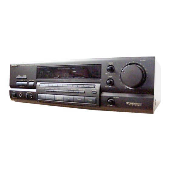
- Page 1 Technics AV control stereo receiver SA-GX770/SA-GX670 SA-GX470/SA-G9057 Operating Instructions "_:" "; ,,..": The photographs show SA-GX770 °, ,. , Before €onnecting, o"petaflng or adjusting this _roduct, ._ please read'these instructions completely. " " "i i"_ ''_'°:' ' " "'"''...
-
Page 2: Table Of Contents
Dear Customer Before Thank you for purchasing this Technics product. For optimum performance and safety, please read Precautions ........these instructions carefully. Accessories ........Front panel controls ......These operating instructions are applicable to models SA- GX770, SA-GX670, SA-GX470 and SA-G9057. - Page 3 The model number and serial number of this product can be Adjusting the sound field found on either the back or the bottom of the unit. Please note them in the space provided below and retain Enjoying sound with DOLBY PRO LOGIC ..21 them for future reference.
-
Page 4: Precautions
Before using this unit please read these operating instructions carefully. Take special care to follow the warnings indicated on the unit itself as well as the safety suggestions listed below. Afterwards keep them handy for future reference. Placement Power Source -- The unit should be connected to power sup- 1. -
Page 5: Accessories
Please c heck andidentify t hesupplied accessories Listening caution supply cord AC power ....... (For USA: SJA172-A or SJA172-1) (For Canada: SJA172-A or SJA172) Selecting fine audio equipment such as the unit you've just pur- chased is only the start of your musical enjoyment. Now it's time to consider how you can maximize the fun and excitement your equipment offers. -
Page 6: Front Panel Controls
For SA-GX770/SA-GX670 Name Re[. page Name Re[. page (_) Power switch (POWER) (_ Headphone Jack (PHONES) (_) Tuning control (TUNING) (_ Direct tuning button (DIRECT TUNING) (_ Tuning mode select button (TUNING MODE) Speaker select buttons (SPEAKERS) (_) Numeric buttons (1-0) 16,19,20 (_ Band select button (BAND) Remote control signal receptor... - Page 7 For SA-GX470/SA-G9057 ÷ I ..I..Name Ref. page Name Ref. page (_ Center mode select button (_ Power switch (POWER) (CENTER MODE) (_ Tuning control (TUNING) (_ Memory button (MEMORY) (_ Band select button (BAND) (_ Treble control (TREBLE) (_) FM mode select button (FM MODE) (_ Bass control (BASS) (_ Direct tuning button...
-
Page 8: Equipment Connections
Technics tape deck and/or CD changer (or CD player) which has the appropriate remote control terminal as shown at the left. If a tape deck is not being used, the CD changer (or CD 0E °... - Page 9 Connecting video equipment Stereo connection cable (not included) White (L)_ Second VCR (for playback only) Monitor TV (not included) (not included) connection cable included) VIDEO AUDIO VIDEO I_._1 l"V ACOUTLETS --'1 MONITOR iN I OUT Cooling fan The cooling fan operates at high power output levels only, c power supply cord connection...
-
Page 10: Antenna Connections
indoor antenna ¢i.cl.ded outdoor antenna .ot i.c .ded This antenna is normally sufficient for reception of FM broad- The outdoor antenna should be used when using the main unit in casts. mountainous areas or in spaces enclosed by reinforced concrete where the FM indoor antenna (included) - Page 11 AM loop antenna (i.et.d d) outdoor antenna (.or included) This antenna is normally sufficient for reception of AM broad- The outdoor antenna should be used when using the main unit in casts. mountainous areas or in spaces enclosed by reinforced concrete where the AM loop antenna (included) does not provide satisfac- tory reception.
-
Page 12: Speaker Connections
Connection of front speakers Placement of speakers Aswell as enjoyingnormalstereo reproductionwith boththe left Right speaker Left speaker and right front speakersconnected, a center speaker and rear (not included) (not included) speakerscan alsobe connectedto the main unit inorderto enjoy playbackwith a feeling of presence usingthe Dolby Pro-Logic Systems. - Page 13 Connection of rear speakers Connection of sub woofer Right speaker Left speaker not included) (not included) The sub woofer is connected when bass sounds are inadequately reproduced because front speakers are too small. When connected, the sub woofer can be placed in any position. This unit has no amplifier section designed especially for the sub woofer, so it is necessary to purchase a sub woofer with a built in amplifier or buy the two separately.
-
Page 14: Basic Operations
VCR 2 INPUT VOLUMe i , i, i , i, ; , i" i , i.;,io i.-J:_ I o I. ,l l o I,-J-I VOLUME VCR 2 front POWER TAPEIDCC input terminals Before operation, set VOLUME to the "0" position. 'tO"seiect 'the des'ired __Press source. -
Page 15: Video
ll,]_,__'._4h[Olk.'.#,__:(;Jri(i Ile ] i_"l'_'1[el)[_ IF4oI_'_'__._DI;9 TREBLE BASS BALANCE SPEAKERS VOLUME SPEAKERS VOLUME __, - ..:..:..:.._ , _.___. Headphones TF'_(not=luOeO> -.O,,NG/ _(not included) -MUTING BALANCE o,o;L = 1/4 inch phoneplug mlP'"g type: stereo type To listen to a desired audio source To adjust the sound... -
Page 16: Listening To Radio Broadcasts
Direct access tuning Specify the frequency using the numeric buttons to directly tune to the desired broadcast station. I;1,]m_.'%_e):_V/ol/_ f_'_ .e'DIol,_ =[,] R,._.,I[etNrB/oIb'IL,_O;(,'Ir4_ _,°' °. i'b"[ _ _O-I ,.,,,,r.,, .... __1_-_-'-' ' =" '"; _-"_ ]-- "- ,,Io. T_IIII-I=,I - tTI-I FM MODE FM MODE I The procedures... -
Page 17: Sequential Tuning
n_,]_-v,.1_:_m_o_'_,_I_:(.Ti[0m Sequential tuning If the frequency is not known, use the tuning control for sear- ching. Auto tuning Manual tuning This automatically searches for broadcast stations which provide The frequency will change only by the amount that the tuning con- strong signal reception. -
Page 18: Preset Tuning
Sequential tuning Preset tuning By presetting the desired broadcast stations into the memory channels of this unit, broadcast stations can be selected simply If the frequency is not known, use the tuning buttons for sear- by pressing numeric button(s). (Refer to page 20 for tuning.) ching. - Page 19 Manual memory presetting Automatic memory presetting ©o°' 6." "",, a_'--'--_T' "_ ..... @ _ _ I T-[i--]'l" i-l-_,l .Q.Q @.©_.@....Se,t tO the desire_J ' broad....to tile frequencY from which want start cast. (Follow steps 1 through 4 on page 16 automatic memory preset.
- Page 20 Preset tuning _ontl.uem To listen to preset broadcast stations ,i,i ..';':, :'7'.r'W'_ I-I-I-I __,_ Q 0 ©_© __speclfy the presei channei using the numeric button(s). (Example: Channel 12) (Within 2 sec.) " [] MANUAL LOCK sPE_<em f"" ! i / \ I / L..
- Page 21 Enjoying sound with DOLBY PRO LOGIC By combining front (A or B), center and rear speakers, SUR- Setting the center mode ROUND mode which conveys a feehng of presence or 3 STEREO mode which ,conveys a feehng of orientation can be enloyed For Dolby Pro-Logic systems, center mode setting is necessary to play back bass sounds effectwely.
- Page 22 Adjusting the output level oF each speaker In order to reproduce the feeling of movement of the sound and clear orientation of sound, it is important to correctly adjust the , , vo,u_ ..Turn'V'oLOME ' io "set the volume level normally used output levels of each speaker.
- Page 23 Enjoying with SURROUND Adjusting delay time 3 STEREO [,..1'z_[_[_i4olb.-]r_,1[e-)[(w4i=, ] nuL, "it_l_' -va e a=ll-_l.gl :!=[gill _, I hi.] iZL_I Adjust SO that the sound from the rear speakers is correctly oriented. D. _ _ -l-u .5_5655_ I-l-I---l- I ..I==i ,u.._ND ..
- Page 24 Tape recording on the tape deck or (VCR 1) recording £rom audio source digital compact cassette deck (DCC) Before recording, prepare the tape deck or DCC for recording Before recording, prepare the VCR (VCR1) for recording (recor- (recording level adjustment, etc.).
- Page 25 Recording from VCR 2 to VCR 1 To record picture from 2 and sound from a different audio source Before recording, prepare the VCR (VCR 1) for recording (recor- ding level adjustment, etc.). Before recording, prepare the VCR (VCR 1) accordingly (recor- See the VCR's operating instructions for details.
- Page 26 Do not attempt to remove the cover(s) or repair the unit yourself. If you make a mistake in operation or if sound output stops due to some operation which was performed, HELP function Refer servicing to qualified personnel only. displays characters which can be useful for indicating the method by which this condition can be remedied.
- Page 27 Some sim- Technics dealer for instructions. ple checks or a minor adjustment on your part may eliminate the (in U.S.A. consult MSC Authorized Servicenters for detailed in- problem and restore proper operation.
- Page 28 • AMPLIFIER SECTION • FM TUNER SECTION Rated minimum sine wave Frequency range 87.9-107.9 RMS power output Sensitivity 11.2 dBf (2 pV, IHF '58) 20 Hz-20 kHz both channels driven 50 dB quieting sensitivity MONO 18.3 dBf (4.5 pV, IHF '58) 0.05% total harmonic...