Table of Contents
Advertisement
www.nordictrack.com
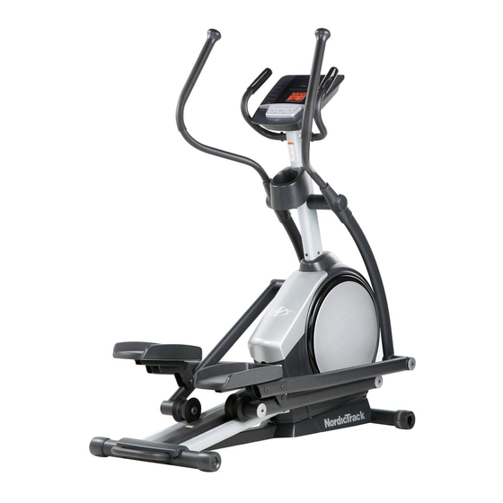
Model No. NTEL07808.0
Serial No.
Write the serial number in the
space above for reference.
@_-%(
(oSeur iadeNrU_d
beerf Dea mle)
QUESTIONS?
As a manufacturer, we are commit-
ted to providing complete customer
satisfaction. If you have questions,
or if parts are damaged or missing,
DO NOT CONTACT THE STORE;
please contact Customer Care.
IMPORTANT: You must note the
product model number and serial
number (see the drawing above)
before contacting us:
CALL TOLL-FREE:
1-888-825-2588
Mon.-Fri. 6 a.m.-6 p.m. MT
Sat. 8 a.m.-4 p.m. MT
ON THE WEB:
www.nordictrackservice.com
"=='=1_ ....
E7
Ff_rlt
E_fiv_
USER'S MANUAL
Advertisement
Table of Contents

Related Manuals for NordicTrack E7 sv


Summary of Contents for NordicTrack E7 sv
- Page 1 "=='=1_ ..Ff_rlt E_fiv_ www.nordictrack.com Model No. NTEL07808.0 USER'S MANUAL Serial No. Write the serial number in the space above for reference. @_-%( (oSeur iadeNrU_d beerf Dea mle) QUESTIONS? As a manufacturer, we are commit- ted to providing complete customer satisfaction.
- Page 2 • Spinning pedals can cause injury. • Reduce pedal speed in a controlled manner. User weight must not exceed 275 pounds. • Replace label if damaged, illegible, or removed, NordicTrack is a registered trademark of ICON IP, Inc.
- Page 3 IMPORTANT PRECAUTIONS...
- Page 4 BEFORE YOU BEGIN Thank you for selecting the new NordicTrack ® E7 SV cover of this manual. To help us assist you, note the FRONT DRIVE elliptical exerciser. The E7 SV FRONT product model number and serial number before con- DRIVE elliptical exerciser provides a wide array of fea- tacting us.
-
Page 5: Assembly
ASSEMBLY Assembly requires two persons. Place all parts of the elliptical exerciser in a cleared area and remove the packing materials. Do not dispose of the packing materials until assembly is completed. In addition to the included tool(s), assembly requires a Phillips screwdriver _====_, two adjustable wrenches _, and a rubber mallet _. - Page 6 Attach the Front Stabilizer (6) to the Frame (1) with two M8 x 80mm Patch Screws (84). Orient the Ramp (3) as shown. Then, insert the Ramp into the Frame (1). Attach the Ramp (3) with five M8 x 19mm Patch Screws (82) and five M8 Split Washers (83).
- Page 7 Apply a small amount of the included grease to the right Crank Arm (20) and to a 19mm Wave Washer (66). Grease Slide a Crank Arm Spacer (55) and the 19mm Wave Washer (66) onto the right Crank Arm (20). Identify the Right Roller Arm (59), which is marked with a "Right"...
- Page 8 Identify the Right Handlebar (61) and the Right Handlebar Leg (60), which are marked with "Right" stickers, and orient them as shown. Make sure that the hexagonal holes are in the indicated location. Slide the Right Handlebar (61) onto the Right Handlebar Leg (60).
- Page 9 Attach an Outer Handlebar Cover (67) and the Inner Handlebar Cover (68) around the Right Handlebar Leg (60) with two M4 x 16mm Screws (104). Repeat this step for the other side of the elliptical exerciser. Apply a small amount of grease to the axle on the Right Handlebar Leg (60) and to a 19mm Wave Washer (66).
- Page 10 10. Attach the Right Pedal Arm (58) to the Right Pedal Bracket (64) with two M10 x 45mm Patch Screws (99). Repeat this step for the Left Pedal Arm (44). 11. Identify the Right Pulse Bar (9), which is marked with a "Right" sticker. Avoid pinching the wires See the inset drawing.
- Page 11 12.Attach theWaterBottle Holder(37)to the Upright ( 4)withtwoM4x 16mmScrews (104). 13.Whilea second person holds theConsole (7) neartheUpright ( 4),connect t heconsole wire Avoid pinching tothe Upper W ireHarness (110). T hen,connect the wires theconsole pulsewirestothe Pulse Wires(63). Console Wire Insert the excess wire downward into the Upright (4).
-
Page 12: To Plug In Power Adapter
HOW TO USE THE ELLIPTICAL EXERCISER HOW TO PLUG IN THE POWER ADAPTER HOW TO MOVE THE ELLIPTICAL EXERCISER Plug one end of the included power adapter into the Due to the size and weight of the elliptical jack on the console. Plug the other end of the power exerciser, moving it requires two persons. -
Page 13: To Exercise On Elliptical Exerciser
HOW TO EXERCISE ON THE ELLIPTICAL HOW TO CHANGE THE INCLINE OF THE RAMP EXERCISER To vary the motion of the pedals, you can change the To mount the elliptical exerciser, hold the handlebars incline of the ramp. To change the incline, press the and step onto the pedal that is in the lower position. - Page 14 CONSOLE DIAGRAM WEIGHT LOSS B l"!,e'! TIME ENDURANCE RESEF ODOMETER WEIGHT LOSS 2.64 ,5u DISTANCE SPEED WEIGIII LOSS PERFORMANCE d fit ?fit TRAINER WEIGHT LOSS WORKOUTS WORKOUTS WORKOUTS iFIT.COM SILENT MAGNETIC RESISTANCE FEATURES OF THE CONSOLE out. iFit workouts control the resistance of the pedals while the voice of a personal trainer coaches you The revolutionary console offers an array of features through your workouts, iFit cards are available sepa-...
- Page 15 HOW TO USE THE MANUAL MODE The lower right display--The lower Begin pedaling or press any button on the right display can console to turn on the console. show the your ped- aling speed (in roB' miles or kilometers A moment after you begin pedaling or press a but- ton, a tone will sound, and the display will light.
- Page 16 Measure your heart rate if desired. If the display does not show your heart rate, make sure that your hands are positioned as described. If there are sheets Be careful not to move your hands excessively or to squeeze the metal contacts tightly. For optimal of clear plastic on Contacts the metal con-...
- Page 17 HOW TO USE A TRAINER WORKOUT ment of the workout. The height of the flashing segment indicates the resistance level for the cur- Begin pedaling or press any button on the rent segment. At the end of each segment of the console to turn on the console.
- Page 18 HOW TO USE A WEIGHT LOSS WORKOUT rent segment. At the end of each segment of the workout, a series of tones will sound and the next Begin pedaling or press any button on the segment of the profile will begin to flash. If a differ- console to turn on the console.
- Page 19 HOW TO USE AN IFIT WORKOUT HOW TO USE THE SOUND SYSTEM Begin pedaling or press any button on the To play music or audio books through the console's console to turn on the console. sound system while you exercise, plug an audio cable (not included) into the jack on the console and into a A moment after you begin pedaling or press a but- jack on your MP3 player or CD player;...
- Page 20 HOW TO CHANGE CONSOLE SETTINGS Select a unit of measurement if desired. The console features a user mode that allows you to The console can show pedaling speed and dis- tance in either miles or kilometers. select a unit of measurement and a backlight option for the console and to view console usage information.
-
Page 21: Maintenance And Troubleshooting
MAINTENANCE AND TROUBLESHOOTING HOW TO ADJUST THE REED SWITCH Inspect and tighten all parts of the elliptical exerciser regularly. Replace any worn parts immediately. If the console does not display correct feedback, the To clean the elliptical exerciser, use a damp cloth and reed switch should be adjusted. - Page 22 EXERCISE GUIDELINES Burning Fat--To burn fat effectively, you must exer- cise at a low intensity level for a sustained period of time. During the first few minutes of exercise, your body uses carbohydrate calories for energy. Only after the first few minutes of exercise does your body begin to use stored fat calories for energy.
- Page 23 PART LIST--Model No. NTEL07808.0 Rloo8A Key No. Qty. Description Key No. Qty. Description Frame Roller Base Pedal Arm Cap Axle Cover Ramp 16mm Wave Washer Upright M4 x 19mm Screw Crank Arm Spacer Front Stabilizer Pedal Bracket Bushing Console Pedal Arm Bushing Left Pulse Bar Right Pedal Arm Right Pulse Bar...
- Page 24 Key No. Qty. Description Key No. Qty. Description M8 x 20mm Washer Upper Wire Harness M8 Locknut Lower Wire Harness M3.5 x 12mm Flat Head Screw Power Adapter M4 x 16mm Screw Drive Belt M4 x 10mm Machine Screw Foam Grip M4 x 16mm Bright Screw 1"...
- Page 25 EXPLODED DRAWING A--Model No. NTEL07808.0 moo8A "" ..-13...
- Page 26 EXPLODED DRAWING B--Model No. NTEL07808.0 RlOO8A 50" 53 c...
- Page 27 EXPLODED DRAWING C--Model No. NTEL07808.0 moo8A...
- Page 28 ORDERING REPLACEMENT PARTS To order replacement parts, please see the front cover of this manual. To help us assist you, be prepared to provide the following information when contacting us: • the model number and serial number of the product (see the front cover of this manual) •...