MTD 340 Series Operator's Manual
Front tine tillers
Hide thumbs
Also See for 340 Series:
- Operator's manual (25 pages) ,
- Owner's manual (16 pages) ,
- Operator's manual (24 pages)
Advertisement
OPERATOR'S
MANUAL
FRONT TINE
TILLERS
Models
340 Thru 390
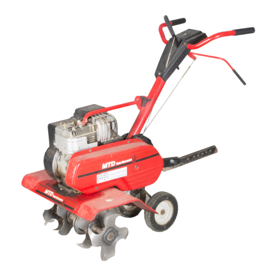
Model 340 Shown
IMPORTANT:
READ
SAFETY
RULES
AND INSTRUCTIONS
CAREFULLY
Warning:
This unit is equipped with an internal combustion
engine and should not be used on or near any unimproved
forest-
covered,
brush-covered
or grass-covered
land unless the engine's
exhaust
system is equipped with a spark arrester meeting
applicable
local or state laws (if any). If a spark arrester is used, it should be maintained
in effective working order by the operator.
In the State of California the above is required by law (Section 4442 of the California Public Resources Code). Other states may have
similar laws. Federal taws apply on federal lands. A spark arrester for the muffler is available through your nearest engine authorized
service dealer or contact the service department,
P.O. Box 368022 Cleveland, Ohio 44136-9722.
MTD PRODUCTS
INC. P.O. BOX 368022 CLEVELAND,
OHIO 44136-9722
PRINTED IN U.S.A.
FORM NO. 770-10132
(10/98)
Advertisement
Table of Contents

Related Manuals for MTD 340 Series


Summary of Contents for MTD 340 Series
- Page 1 Federal taws apply on federal lands. A spark arrester for the muffler is available through your nearest engine authorized service dealer or contact the service department, P.O. Box 368022 Cleveland, Ohio 44136-9722. MTD PRODUCTS INC. P.O. BOX 368022 CLEVELAND, OHIO 44136-9722 PRINTED IN U.S.A.
-
Page 2: Section 2: Calling Customer Support
Operator's Manual. The information on the model plate is very important if you need help from your dealer or the MTD customer support department. See Figure 1. • Every tiller has a model plate. You can locate it by standing in the operating position behind the unit and looking down at the frame on the right side. -
Page 3: Safe Operation
SECTION 3: IMPORTANT SAFE OPERATION PRACTICES WARNING: THIS SYMBOL POINTS OUT IMPORTANT SAFETY INSTRUCTIONS WHICH, IF NOT FOLLOWED, COULD ENDANGER THE PERSONAL SAFETY AND/OR PROPERTY YOURSELF AND OTHERS. READ AND FOLLOW INSTRUCTIONS IN THIS MANUAL BEFORE ATTEMPTING TO OPERATE YOUR TILLER. FAILURE TO COMPLY WITH THESE INSTRUCTIONS... -
Page 4: Your Responsibility
• Only useaccessories approved forthismachine by • Extinguish all cigarettes, cigars, pipes and other themanufacturer. Read, understand, andfollow all sources of ignition. instructions provided with theapproved accessory. • Never refuel unit indoors because flammable • If situations occurwhich arenotcovered b y this vapors will accumulate in the area. - Page 5 SECTION 4: UNPACKING INSTRUCTIONS Remove staples, break glue on top flaps, or cut Extend control cable(s) to the rear of the tiller tape at carton end and peel along top flap to and lay them on the floor. Be careful not to bend open carton.
- Page 6 Lock Nut Handle --- "Z" End Brace Spark Hooked In Plug Bracket Threaded Cable Models 340 thru 345 Models 340, 342, & 390 Figure 6 REVERSE CABLE Spark (Model 390 Only) Plug The reverse clutch cable is the cable which Handle attached closer to the front of the tiller.
-
Page 7: Section 7: Operation
With tine engagement handle neutral Reverse Tine (released) as shown in Figure 8, pull the starter _ngagement Handle rope several times. The tines should not turn. If they turn forward, loosen the hex nut on the forward cable (underneath handle assembly). -
Page 8: To Stop Engine
Repeat steps 4 and 5 until engine starts. Refer to Models 340, 342, & 390 engine manual for additional engine information. Attach spark plug wire to spark plug. Make NOTE: After starting engine and prior to using the certain the metal loop on the end of the spark tiller, be certain to check the clutch adjustment plug wire (inside the boot) is fastened securely described... - Page 9 CONTROLLING SPEED AND TILLING Transport DEPTH Position Depth Wheel Yoke Adjustment: Place wheel yoke so Stake that wheels are forward (nearest point between wheels and tines) for shallow tilling, cultivating and transport. The forward speed will increase. Turn yoke around (farthest point Shallow"-._"...
- Page 10 Throttle Control: throttle control lever The tiller has many uses other than tilling and cultivating a garden. One of these is the preparation adjusts the engine speed and stops the engine. of lawn area for seeding. The tiller will prepare a With the throttle control lever pushed completely deep seed bed which will be free of hard untilled forward,...
-
Page 11: Section 10: Maintenance
NOTE: A dirty air cleaner will cause engine to run rough, Be certain air cleaner is clean and attached to the carburetor before adjusting carburetor. Do not make unnecessary adjustments. Factory settings are satisfactory for most applications and conditions. SECTION 9: LUBRICATION WARNING: Always... -
Page 12: Belt Removal
CLEANING THE TINE AREA Transmission Clean the underside of the tine shield after each use. Reverse Pulley The dirt washes off the tines easier if washed off Idler immediately instead of after !t dries. Pulley BELT REMOVAL AND REPLACEMENT Your tiller has been engineered with belts made of special material (Kevlar Tensile). -
Page 13: Shooting Guide
SECTION 11: OFF-SEASON STORAGE If the tiller is to be inoperative for a period longer Protect the inside of the engine for storage as than days, following precautions instructed in the separate engine manual packed recommended. with your tiller. Working outdoors, drain all fuel... - Page 14 Model 340 thru 345 /_52...
- Page 15 Model 340 thru 345 PART NO. DESCRIPTION i712-3004A Hex Flange L-Nut 5/16-18 Thd. (Gr. 5) i 786-0004 Tail Piece Brkt. (R.H.) 736-0140 FI-Wash, .385" I.D. x .62" O.D. 786-0003 Tail Piece Brkt. (LH.) 731-1645A Clutch Handle Holder 710-0805 720-0269 Hex Bolt 5/16-18 x 1.5" Lg. Grip_lutch 750-0890 686-0083...
- Page 16 Model 340 thru 345...
- Page 17 Model 340 thru 345 REF, PART R EF. PART DESCRIPTION DESCRIPTION Belt Cover 786-0056 756-0972 Outer Engine Pulley Half 736-3020 FI-Wash..266" I.D. x .625" O.D. 756-0971 Inner Engine Pulley Half 710-0599 756-0585 Hex Wash. Hd. TT-Tap Scr. 1/4-20 x .5" FI-Pulley 6"...
- Page 18 Model 390...
- Page 19 Model 390 REF. I RER PARTNO. DESCRIPTION PART NO. DESCRIPTION 712-3004A 32 720:0270A _ri_AeverseEever Hex Flange L-Nut 5/16-18 Thd, (Gr. 5) 786-0004 686-0014A Tail Piece Brkt. (R.H.) Reverse Handle Ass'y. 786-0003 i726-0135 Tail Piece Brkt. (LH.) Cap Speed Nut 710-0805 731-1645A Clutch Handle Holder Hex Bolt 5/16-18 x 1.5"...
- Page 20 Model 390...
- Page 21 Model 390 I REF DESCRIPTION PART NO. DESCRIPTION I NO" PART NO. 756-0971 I-nner Engine Pulley Half Belt Cover ..ii ..786-O057 756-0585 FI-Wash..266" I.D. x .625 O.D. FI-Pulley 6" Dia. 736-3020 754-0429 "V"-Belt (Reverse) Hex Washer TT-Tap Scr. 1/4-20 x .5" 710-0599 754-0428 "V"-Belt (Forward)
- Page 22 MANUFACTURER'S LIMI ED WARRANTY For TWO YEARS from the date of retail purchase States of America, its possessions and territories, within the United States of America, its possessions except those sold through manufacturer's authorized channels of export distribution. and territories, the manufacturer will, at its option, repair or replace, for the original purchaser, free of...