Table of Contents
Advertisement
Quick Links
Advertisement
Table of Contents

Related Manuals for EVGA 123-CD-E635


Summary of Contents for EVGA 123-CD-E635
-
Page 1: User's Guide
User’s Guide EVGA H55 Motherboard... -
Page 2: Table Of Contents
User’s Guide ... 1 EVGA H55 Motherboard ... 1 Before You Begin… ... 6 Parts NOT in the Kit ... 6 EVGA H55 Motherboard ... 7 Motherboard Specifications... 7 Hardware Installation ... 9 Safety Instructions ... 9 Preparing the Motherboard ... 10 Installing the CPU ... - Page 3 North Bridge Configuration ... 32 PCI Express Configuration ... 32 PCI/PNP Resource Management ... 34 Clear NVRAM ... 34 Plug & Play O/S ... 34 PCI Latency Timer ... 34 Allocate IRQ to PCI VGA ... 35 Palette Snooping ... 35 EVGA H55 Motherboard...
- Page 4 CPU Fan Mode Setting ... 38 Frequency/Voltage Control Menu ... 39 Memory Configure ... 39 CPU Configuration ... 39 Installing Drivers and Software ...40 Windows XP/Vista/7 Driver Installation ... 40 Appendix A. POST Codes for the EVGA H55 Motherboard ...41...
- Page 5 Figure 6. PCI/PNP Resource Management ... 34 Figure 7. Boot Configuration Features ... 36 Figure 8. Power Management Features ... 37 Figure 9. Hardware Health Configure ... 38 Figure 10. Frequency/Voltage Control ... 39 EVGA H55 Motherboard List of Figures...
-
Page 6: Before You Begin
Power Supply EVGA assumes you have purchased all the necessary parts needed to allow for proper system functionality. For a full list of supported CPU’s on this motherboard, please visit http://www.evga.com/support/motherboard/. When replacing a motherboard in a system case, you will need to reinstall an operating system even though the current hard disk may already have an operating system. -
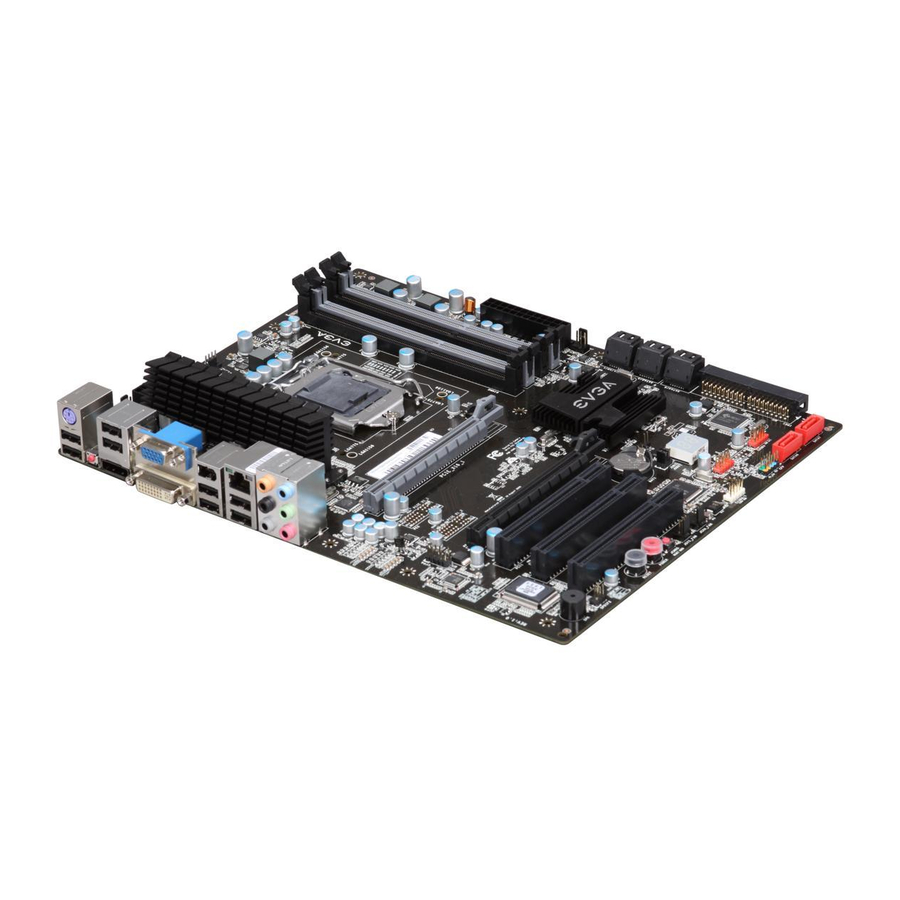
Page 7: Evga H55 Motherboard
USB 2.0 Ports Supports hot plug Twelve USB 2.0 ports (Eight rear panel ports, four onboard USB headers) Supports wake-up from S1 and S3 mode Supports USB 2.0 protocol up to a 480 Mbps transmission rate EVGA H55 Motherboard... - Page 8 Eight(8) onboard Serial ATA II 300MBps data transfer rate Two Serial ATA II connectors from JMicron’s JMB363 with support for RAID 0, RAID 1 Onboard LAN Integrated LAN port’s Supports 10/100/1000 Mb/sec Ethernet Onboard IEEE1394a (Firewire) Support hot plug Two IEEE1394a ports (One rear panel port, one onboard 1394 header) with a rate transmission of 400 Mbps Onboard Audio...
-
Page 9: Hardware Installation
This section will guide you through the installation of the motherboard. The topics covered in this section are: Preparing the motherboard Installing the CPU Installing the CPU fan Installing the memory Installing the motherboard Connecting cables ... -
Page 10: Preparing The Motherboard
Preparing the Motherboard Installing the CPU Be very careful when handling the CPU. Hold the processor only by the edges and do not touch the contacts on the motherboard or CPU. Any physical damage to the motherboard pins will void the warranty. Use the following procedure to install the CPU onto the motherboard: Unhook the socket lever by pushing down and... -
Page 11: Installing The Cpu Fan
Align the notches in the processor with the notches on the socket. Lower the processor straight down into the socket without tilting or sliding it into the socket Note: Make sure the CPU is fully seated and level. Lower the load plate so it is resting on the CPU. -
Page 12: Installing System Memory (Dimms)
Installing System Memory (DIMMs) Your new motherboard has four 240-pin slots for DDR3 memory. These slots support 256 MB, 512 MB, 1GB, 2GB, 4GB DDR3 technologies. There must be at least one memory bank populated to ensure normal operation. Use the following the recommendations for installing memory. -
Page 13: Installing The I/O Shield
Installing the I/O Shield The motherboard kit comes with an I/O shield that is used to block radio frequency transmissions, protects internal components from dust and foreign objects, and promotes correct airflow within the chassis. Before installing the motherboard, install the I/O shield from the inside of the chassis. -
Page 14: Securing The Motherboard Into A System Case
Securing the Motherboard into a System Case Most system cases have a base with mounting studs or spacers to allow the motherboard to be secured to the chassis and help to prevent short circuits. If there are studs that do not align with a mounting hole on the motherboard, it is recommended that you remove that stud to prevent the possibility of a short circuit. -
Page 15: 24-Pin Atx Power (Pw1)
24-pin ATX Power is the main power supply connector located along the edge of the board next to the DIMM slots. Make sure that the power supply cable and pins are properly aligned with the connector on the motherboard. Firmly plug the power supply cable into the connector and make sure it is secure. -
Page 16: Connecting Ide Hard Disk Drives
Connecting IDE Hard Disk Drives The IDE connector supports Ultra ATA 133/100/66 IDE hard disk drives. Connect the blue connector (the cable end with a single connector) to the motherboard. Connect the black connector (the cable with the two closely spaced black and gray connectors) to the Ultra ATA master device. -
Page 17: Connecting Serial Ata Cables
Connecting Serial ATA Cables The Serial ATA II connector is used to connect the Serial ATA II device to the motherboard. These connectors support the thin Serial ATA II cables for primary storage devices. The current Serial ATA II interface allows up to 300MB/s data transfer rate. -
Page 18: Connecting Internal Headers
Connecting Internal Headers Front Panel Header The front panel header on this motherboard is one connector used to connect the following four cables. (see Table 2 for pin definitions): PWRLED Attach the front panel power LED cable to these two pins of the connector. -
Page 19: Ieee1394A (Firewire)
IEEE1394a (Firewire) This motherboard has one IEEE 1394a onboard header. Alternatively, you can also connect this to your system case (if applicable). Secure the bracket to either the front or rear panel of the system case (not all system cases are equipped with the front panel option). Connect the end of the cable to the IEEE1394a header on the motherboard. -
Page 20: Usb Headers
USB Headers This motherboard contains eight (8) USB 2.0 ports that are exposed on the rear panel of the chassis (Figure 2). The motherboard also contains two (2) 10- pin internal header connectors onboard that can be used to connect an optional external bracket containing up to four (4) USB 2.0 ports. -
Page 21: Audio
Audio The audio connector supports HD audio standard and provides two kinds of audio output choices: the Front Audio, the Rear Audio. The front Audio supports re-tasking function. Table 5. Front Audio Connector Connector Front Audio Connector Signal PORT1_L AUD_GND PORT1_R PRECENCE_J PORT2_R... -
Page 22: Expansion Slots
Expansion Slots PCI Slots The PCI slot supports many expansion cards such as a LAN card, USB card, SCSI card and other cards that comply with PCI specifications. When installing a card into the PCI slot, be sure that it is fully seated. Secure the card’s metal bracket to the chassis back panel with the screw used to hold the blank cover. -
Page 23: Onboard Buttons
Onboard Buttons These onboard buttons include RESET, POWER and Clear CMOS. These functions allow you to easily reset the system, turn on/off the system, or clear the CMOS. Clear CMOS Button The motherboard uses the CMOS RAM to store all the set parameters. The CMOS can be cleared by pressing the Clear CMOS button either onboard or on the external I/O Panel. -
Page 24: Post Port Debug Led And Led Status Indicators
Post Port Debug LED and LED Status Indicators Post Port Debug LED Provides two-digit POST codes to show why the system may be failing to boot. It is useful during troubleshooting situations. This Debug LED will also display current CPU temperatures after the system has fully booted into the Operating System. -
Page 25: Configuring The Bios
This section discusses how to change the system settings through the BIOS Setup menus. Descriptions of the BIOS parameters are also provided. This section includes the following information: Enter BIOS Setup Main Menu Standard BIOS Features Advanced BIOS Features ... -
Page 26: Enter Bios Setup
Enter BIOS Setup The BIOS is the communication bridge between hardware and software. Correctly setting the BIOS parameters is critical to maintain optimal system performance and stability. Use the following procedure to verify/change BIOS settings. Power on the computer. Press the key when the following message briefly displays at the bottom of the screen during the Power On Self Test (POST). -
Page 27: Figure 2. Cmos Setup Utility Main Menu
Figure 2. CMOS Setup Utility Main Menu Standard BIOS Features Use this menu to set up the basic system configuration. Advanced BIOS Features Use this menu to set up the advanced system features and boot sequence. Advanced Chipset Features ... -
Page 28: Standard Bios Features Menu
Standard BIOS Features Menu The Standard CMOS Features menu is used to configure the standard CMOS information, such as the date, time, and so on. Use the through the options. Use the arrow keys to position the selector in the option you choose. -
Page 29: System Time / System Date
System Time / System Date Using the arrow keys, position the cursor over the month, day, and year. Use keys to scroll through dates and times. Note that the weekday (Sun through Sat) cannot be changed. This field changes to correspond to the date you enter. -
Page 30: Advanced Bios Features
Advanced BIOS Features Access the Advanced BIOS Features menu from the CMOS Setup Utility screen. Use the display the sub-menu. Use the arrow keys to position the selector in the option you choose. To go back to the previous menu, press The options that have associated sub-menus are designated by a , which precedes the option. -
Page 31: Boot Settings Configuration
Boot Settings Configuration Use this option to configure various system options, such as Bootup Num-Lock status, Quiet Boot and other advanced features. USB Configuration This option menu allows you to enable Legacy USB support, force USB 1.1 mode and more. Configuring the BIOS... -
Page 32: Advanced Chipset Features
Advanced Chipset Features Select Advanced Chipset Features from the CMOS Setup Utility menu and press to change the settings. Enter CMOS Setup Utility – Copyright (C) 1985-2005, American Megatrends Advanced Chipset Settings ______________________________________________ WARNING: Setting wrong values in below sections may cause system to malfunction. - Page 33 This function allows you to enable or disable the onboard secondary network controller. It is recommended to leave this enabled, unless you are using an external Network Controller, such as an EVGA Killer Xeno card. JMicron Storage Controller ...
-
Page 34: Pci/Pnp Resource Management
PCI/PNP Resource Management Select PCI/PNP Resource Management from the CMOS Setup Utility menu and press to display the advanced settings. Enter CMOS Setup Utility – Copyright (C) 1985-2005, American Megatrends Advanced PCI/PnP Settings ______________________________________________ WARNING: Setting wrong values in below sections may cause system to malfunction. -
Page 35: Allocate Irq To Pci Vga
Allocate IRQ to PCI VGA This function allows an IRQ to be assigned to a PCI VGA. Palette Snooping This function allows the BIOS to inform the system that an ISA graphics device is installed. PCI IDE BusMaster This function allows the BIOS to use PCI BusMastering for reading or writing to IDE drives. -
Page 36: Boot Configuration Features
Boot Configuration Features Select Boot Configuration Features from the CMOS Setup Utility menu and press to display the settings. Enter CMOS Setup Utility – Copyright (C) 1985-2005, American Megatrends Boot Device Priority Hard Disk Drives :Move Enter:Select F7:Previous Values :Move Enter:Select F5:Previous Values... -
Page 37: Power Management Features
Power Management Features Select Power Management Features from the CMOS Setup Utility menu and press to display the settings. Enter CMOS Setup Utility – Copyright (C) 1985-2005, American Megatrends Power Management Features ______________________________________________ ACPI Configuration SLP_S4# Min. Assertion Width Restore on AC Power Loss :Move Enter:Select... -
Page 38: Hardware Health Configure
Hardware Health Configure Select Hardware Health Configure from the CMOS Setup Utility menu and press to display the settings. Enter CMOS Setup Utility – Copyright (C) 1985-2005, American Megatrends Hardware Health Configure H/W Health Function ______________________________________________ CPU Temperature Sensor VREG Temperature Sensor System Temperature Sensor CPU Fan Speed Power Fan Speed... -
Page 39: Frequency/Voltage Control Menu
Frequency/Voltage Control Menu Select Frequency/Voltage Control from the CMOS Setup Utility menu and press to display the settings. Enter CMOS Setup Utility – Copyright (C) 1985-2005, American Megatrends Memory Configure CPU Configuration Target CPU Frequency: 3466 MHz (133x26) Target Memory Frequency: 1333 MHz (2:10) CPU Multiplier Setting CPU Frequency Setting... -
Page 40: Installing Drivers And Software
The CD that has been shipped with the EVGA H55 SLI Motherboard contains the following software and drivers: Chipset Drivers Audio drivers LAN Drivers EVGA E-LEET Overclocking Utility Adobe Acrobat Reader User’s Manual Windows XP/Vista/7 Driver Installation Insert the Intel H55 installation CD for the motherboard included in the kit. -
Page 41: Appendix A. Post Codes For The Evga H55 Motherboard
Appendix A. POST Codes for the EVGA H55 Motherboard This section provides the AMI POST Codes (Table 6) for the EVGA H55 Motherboard during system boot The POST Codes are displayed on the Debug LED readout located directly onboard the motherboard. - Page 42 Code Description Detect Keyboard Test input devices Early POST initialization of chipset registers Relocate System Management interrupt vector Uncompress and initialize BIOS module Initialize devices primary Initialize devices secondary Initialize output devices Allocate memory for ADM module Initialize silent boot module Display sign-on message Initialize USB controller Initialize DMAC-1 &...
- Page 43 Code Description Uninstall POST vector Prepare BBS for Int 19 boot End of POST initialization Save system context for ACPI Pass control to OS (can vary) Show CPU Temp (if enabled)
-
Page 44: Evga Glossary Of Terms
EVGA Glossary of Terms ACPI - Advanced Configuration and Power Interface AFR – Alternate Frame Rendering APIC - Advanced Programmable Interrupt Controller BIOS - Basic Input Output System CD-ROM - Compact Disc Read-Only Memory CMOS - Complementary Metal-Oxide Semiconductor CPU – Central Processing Unit D-ICE –... - Page 45 Configuring the BIOS JEDEC - Joint Electron Device Engineering Council LAN - Local Area Network LCD - Liquid Crystal Display LGA – Land Grid Array LN2 – Liquid Nitrogen Cooling MAC - Media Access Control MCP - Media and Communications Processor MHz - Megahertz NB - Northbridge NCQ - Native Command Queuing...
- Page 46 TCP/IP - Transmission Control Protocol/Internet Protocol USB - Universal Serial Bus VDroop - V-core Voltage Drop VGA - Video Graphics Array...