
Related Manuals for Panasonic P2HD AJ-HRW10G


Summary of Contents for Panasonic P2HD AJ-HRW10G
-
Page 1: Operating Instructions
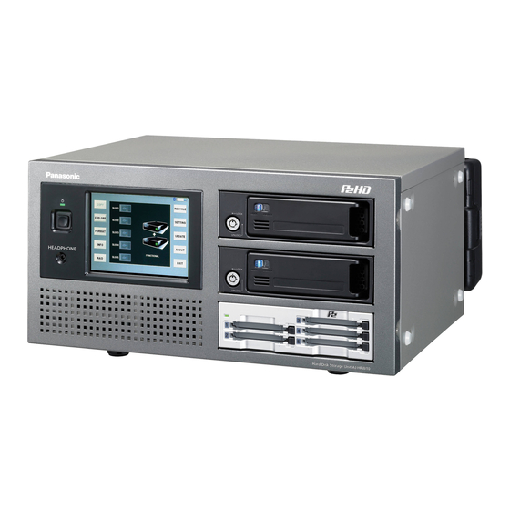
Operating Instructions Hard Disk Storage Unit AJ-HRW10G Model No. Before operating this product, please read the instructions carefully and save this manual for future use. ENGLISH S0409H0 -M Printed in Japan VQT2C68... -
Page 2: Read This First
AJ-HRW10G RISK OF ELECTRIC SHOCK Trade Name: PANASONIC DO NOT OPEN Responsible Party: Panasonic Corporation of North America One Panasonic Way, Secaucus, NJ 07094 CAUTION: TO REDUCE THE RISK OF ELECTRIC SHOCK, DO NOT REMOVE COVER (OR BACK). Support contact: Panasonic Broadcast &... - Page 3 Read this first! (continued) A rechargeable battery that is recyclable powers the product you have purchased. <For USA-California Only> This product contains a CR Coin Cell Lithium Battery which contains Perchlorate Material — special handling may apply. See www.dtsc.ca.gov/hazardouswaste/perchlorate. To remove the battery Main Power Battery (Ni-Cd / Ni-MH / Li-ion Battery) To detach the battery, please proceed in the reverse order of the installation method described in this manual.
-
Page 4: Table Of Contents
Contents Read this first! ..........2 Checking the clips in P2 card/HDD ..25 Standard accessories .........5 Copying individual clips (COPY) ......27 Deleting individual clips (DELETE) ....... 27 Precautions for Use........5 Viewing clip properties (PROP) ......28 Overview............5 Select listed devices (device selection buttons) ... 29 Selecting clips to display (FILTER) ....... -
Page 5: Standard Accessories
Standard accessories ● Ferrite core × 4 ● Screws x 16 When using a LAN cable (optional), make sure For installing the 5-inch bay units (page 9) to attach ferrite cores to the ends of the cable. (page 13) ● Front cushion x 1 Failure to attach ferrite cores could cause A cushion to protect the front surface when the unit is... -
Page 6: Control Reference Guide
Control reference guide Front Panel HDD1 HDD2 HEADPHONES A Front POWER LED F 5-inch bay units used to install the HDD Lights when the unit is ON. You can install the HDD (SATA) which you When the LED goes off and the rear POWER purchased with the 5 inch bay unit. -
Page 7: Back Panel
Control reference guide (continued) Back Panel 1GBASE-TX DC IN POWER A Battery holder F LAN connector You can install the battery directly if it is compatible These LAN connectors support speeds of 1000, with Anton Bauer battery holders. 100 and 10 Mbps. Please set the IP address in GUI of this unit. -
Page 8: Power Supply
Power Supply A battery or external DC power supply can be used as Removing the battery the power supply for the unit. Completely push down and hold the release lever Mounting the Battery on the battery holder. Then, slide the battery in the opposite direction to the arrow while holding the lever down. -
Page 9: How To Install The 5-Inch Bay Units
How to install the 5-inch bay units Follow the steps below to install the 5-inch bay units. 5-inch bay units and HDDs sold separately. Remove the screws (x2 each) securing the Remove the screws (x2) of the top panel, and 5-inch bay unit cover to the front panel, and remove the top panel. - Page 10 How to install the 5-inch bay units (continued) Install the removed brackets on the 5-inch Put the front panel back in its original bay unit. position (using the 4 screws). (Use the screws provided.) 5-inch bay unit brackets Close the top panel, and tighten the top panel screws (x2).
-
Page 11: For Better Performance
For better performance This unit is constructed to allow the HDDs to be Moving the unit installed on 5-inch bay units, but its design does not When moving the unit, protect the front panel with the improve the HDD drop resistance or impact resistance front cushion. -
Page 12: Recorded Data
This unit supports mirror (RAID1) operation. Please panel. consider the worst situation of the operations. Panasonic is not liable for data lost from P2 card or HDD failure or other problems, or for other direct or indirect loss. Cleaning Never clean the unit with solvents such as benzene, thinner, or alcohol. -
Page 13: Precautions When Connecting The Lan Cable
For better performance (continued) Precautions when connecting the LAN cable • When connecting the unit to a computer using a LAN cable, attach the two ferrite cores (included) on the LAN cable, one 5–10 cm from the computer LAN port and the other 5–10 cm from the LAN port on the unit. -
Page 14: Basic Operations
Basic operations Inserting P2 card When inserting a P2 card into the P2 card slot of the P2 drive provided in the unit, be absolutely sure to position the P2 card parallel to the slot and insert it straight into the drive. •... -
Page 15: Turning The Unit On And Off / Exiting
Basic operations (continued) Turning the unit ON and OFF / Exiting Confirm that the battery or external DC power supply Power OFF is firmly connected to the unit. Please refer to the To turn off the power, either press the front POWER operation instructions of this unit for the details of button or the EXIT button on the main screen access. -
Page 16: Functions
Basic operations (continued) Power indication Functions Power indication Described below are the functions of the buttons which The icon at the top right of the screen indicates the are provided on the left and right sides of the main power supply status as shown by the displays below. screen. -
Page 17: Setting The Raid Function
Setting the RAID function The RAID function must be set when a new HDD has been installed. RAID1 mode: The same data is written simultaneously onto two HDDs. The data safety is ensured by data redundancy (mirroring). When HDDs with different memory sizes are combined, the smaller memory size will be used. JBOD mode: The data is written onto only the specified HDD. -
Page 18: Viewing Basic Raid Information (Basic Information)
Setting the RAID function (continued) Viewing basic RAID information Setting up RAID drives (Create RAID) (Basic Information) When RAID is re-set, the data on the HDD will be The statuses concerning the HDDs used and RAID are deleted so take care before proceeding. displayed. -
Page 19: Deleting Raid Drives (Delete Raid)
Setting the RAID function (continued) Deleting RAID drives (Delete RAID) Press NEXT button after setting, the confirming screen When switching between RAID1 and JBOD or will display. Please press OK button. otherwise changing the RAID level, delete the logical drive which is currently set. (In the RAID1 mode) When the RAID level is re-set, the data on the HDD will be deleted so take care before proceeding. -
Page 20: Rebuilding Raid Drives (Rebuild)
Setting the RAID function (continued) Rebuilding RAID drives (Rebuild) When data rebuilding is necessary or during When the STOP button has been pressed, a the rebuilding process, either “Need Rebuild” or confirmation message such as the one shown “Rebuilding” is displayed under the HDD icon on the below is displayed. -
Page 21: Raid Setting
Setting the RAID function (continued) RAID Settings The basic processing of the RAID1 function is set. B Automatic Rebuilding Status ● Enable button Rebuild automatically. ● Disable button Rebuild manually. To initiate rebuilding, press the START button of the Rebuild tab. C Buzzer Status These control the ON/OFF statuses of the BUZZER on the RAID board. -
Page 22: Copying
Copying The data on the recorded P2 cards is copied onto the HDD. The data is copied from the P2 card onto the HDD on a card by card basis or clip by clip basis (see page 27). Use the copying method that best suits the application concerned. Copying entire cards Manual copy mode Two copy modes are available when copying entire... -
Page 23: Auto Copy Mode
Copying (continued) Manual copy mode (continued) Auto copy mode Take the steps below for manual copying. In auto copy mode, a popup screen is displayed when a P2 card is inserted. In SOURCE, select the P2 card to copy. (More than one card can be selected using SLOT1 to SLOT5.) In DESTINATION, select the destination for copying. -
Page 24: Confirmation After Copying
Copying (continued) Once copying starts in manual or auto copy mode, the Confirmation after copying sequence of processing is as follows. The copying state and the progress of each card The results of copying can be checked on the copy displays on the screen. -
Page 25: Checking The Clips In P2 Card/Hdd
Checking the clips in P2 card/HDD Open EXPLORE screen, you will find that data in different device displays in different ways. P2 card : Thumbnail HDD : Folder To display the clips on the HDD, double-click the folder for the day when the data was copied. All thumbnails in the folder are shown. - Page 26 Checking the clips in P2 card/HDD (continued) P2 card : Thumbnail HDD : Folder L Shot marks P V_FORMAT These are displayed on the clips which have been The recording signal format of the clip (yellow provided with shot marks. framed) where the cursor is positioned is displayed here.
-
Page 27: Copying Individual Clips (Copy)
Checking the clips in P2 card/HDD (continued) Copying individual clips (COPY) Deleting individual clips (DELETE) When the DELETE button is pressed on the EXPLORE This function button is not displayed when HDD is screen, the selected clip (blue framed) can be deleted. selected. -
Page 28: Viewing Clip Properties (Prop)
Checking the clips in P2 card/HDD (continued) Viewing clip properties (PROP) D NEXT button When the PROP button is pressed on the EXPLORE screen, the properties of the clip where the cursor is The property of the one chip after the one in cursor located (yellow framed) will be displayed. -
Page 29: Select Listed Devices (Device Selection Buttons)
Checking the clips in P2 card/HDD (continued) Select listed devices (device selection buttons) soft keyboard When the Device Selection Button is pressed on the EXPLORE screen, the devices to be displayed on the thumbnail screen are selected. A MODE The names of the modes corresponding to the items are displayed here. -
Page 30: Selecting Clips To Display (Filter)
Checking the clips in P2 card/HDD (continued) Selecting clips to display (FILTER) After entering the keyword, press the APPLY button When the FILTER button is pressed on the EXPLORE and the OK button to proceed with filtering. screen, the combinations to be displayed on the thumbnail screen can be selected. -
Page 31: Changing How Clips Are Listed (Sort)
Checking the clips in P2 card/HDD (continued) Changing how clips are listed (SORT) Viewing slot numbers and HDD status Change the displaying order of the selected clips. This indicates the P2 card or HDD containing the clip The following display appears when the SORT button where the cursor is positioned. -
Page 32: Playing The Clips
Playing the clips The PLAYER application starts up when the PLAY button is pressed after the clips to be played have been selected on the EXPLORE screen. (PREV button) I VOLUME The slider is slid by operating the + and - buttons Each time this button is pressed, play jumps to the on the left. -
Page 33: Setting The Ff/Rew Rate
Playing the clips (continued) Setting the FF/REW rate Set the speed in the REW and FF. When SETTING button is pressed on the PLAYER application screen, the following screen appears. A 4Xspeed button Clips are played rapidly while skipping frames at a speed equivalent to 4 times the normal speed. -
Page 34: Sharing The Folders
Sharing the folders A shared setting can be established to allow the folders of an HDD selected on the "EXPLORE" screen to be accessed from another computer. Please set Network in SETTING screen in advance. (page 38) Accessing via network will not enable if you do not set so. -
Page 35: Returning The Clips In The Recycle Folder
Returning the clips in the RECYCLE folder When the RECYCLE button is pressed on the main screen, the RECYCLE screen is displayed. The clips in the RECYCLE folder and folders can now be displayed, deleted or restored. A SELECT ALL button / UNSELECT ALL button C ERASE button Pressing the SELECT ALL button enables you This completely erases the selected folder and... -
Page 36: Formatting
Formatting To format a P2 card or HDD, press the FORMAT button on the main screen. The device selection screen to be formatted now appears. A FORMAT SLOTS button • Be careful when formatting media or devices. SLOT1 button/SLOT2 button/SLOT3 button/ Formatting will erase all data on P2 cards or HDDs. -
Page 37: Checking The State Of All Slots
Checking the state of all slots Press INFO button in the main screen, the INFO screen will display. You can check the volume of P2 cards in any slot or the HDDs. The default volume name is DVCPRO HD. If you want to check the volume in other format, please press FORMAT select button on the bottom of the screen. -
Page 38: System Setting
System setting Press SETTING button to set the system in the main screen. This SETTING screen is constructed by plural TAB as the following. For details, refer to the explanations for each individual tag Configuring network settings (Network) Specifying the display language (Language) Set network access of LAN1 as well as LAN2. -
Page 39: Specifying Copy Options (Copy Setting)
System setting (continued) Specifying copy options (Copy Setting) Changing thumbnail display (Thumbnail) Set the option functions in copying. Specify how the thumbnail screen is organized for clips shown on the "EXPLORE" screen. A Verify Compare source and destination data after copying A 3×2 button is finished. -
Page 40: Checking Smart Info
System setting (continued) Checking SMART Info “SMART” is an abbreviation of “Self-Monitoring, B Temperature Threshold Set Analysis and Reporting Technology”. Alarm messages are displayed if HDDs exceed the This function is incorporated within hard disk drives in specified temperature. If the APPLY button is not order to quickly discover any problems the drive and pressed after these settings have been changed, estimate the extent of the damage. -
Page 41: Setting Battery Level Warnings (Battery)
System setting (continued) Setting battery level warnings (Battery) Setting the date and time (Date and Time) Change battery settings. Set the unit's date and time. Settings can be made for two different batteries – Battery1 and Battery2 – which may then be selected as required A yyyy-mm-dd Set the date (year/month/day). -
Page 42: Undoing The Setting (Default)
System setting (continued) Undoing the setting (Default) The setting is undone. A INITIALIZE button Use this to restore all the settings except the ones below to the factory settings. • Network • Battery B CLOSE button Return to the main screen. To restore the settings to the factory settings, press the INITIALIZE button. -
Page 43: Maintenance
Maintenance Checking HDD status (Maintenance) Select the HDD to check. The operations of the installed HDD can be checked on the screen which appears when the maintenance button on the SETTING screen is pressed. Press the Start Test button. The inserted HDD is easily damaged. The display changes to [STOP]. -
Page 44: Creating Pass Registration Data
Maintenance (continued) Creating PASS registration data Selecting a workgroup Register as a PASS (P2 Asset Support System) You can choose either MSHOME or WORKGROUP as member to use P2 Status Logger, an inspection utility the name of the workgroup to be used by the network. for P2 devices. -
Page 45: Version Up
The version update module which is If a new version is found, the version will be downloaded from the Panasonic home page updated automatically. A message prompting contains compressed files so unzip them. you to restart the unit is then displayed so restart the unit. -
Page 46: Connecting To A Computer
Connecting to a computer Network connecting Inserting the HDD directly in the 5 inch bay unit When data sharing has been set using the SHARE If identical 5-inch bay units have been installed, the function, the HDD data which has been set to be HDDs unmounted from the unit can be connected shared over the network can be accessed. -
Page 47: Specifications
Specifications Power supply DC 12 V (11 V to 17 V) Power consumption 70 W indicates safety information. External IF LAN1/LAN2 : Gigabit Ethernet LAN port Dimensions (W) × (H) × (D) 368 mm × 177 mm × 303 mm (14.49 inches ×... - Page 48 Information for Users on Collection and Disposal of Old Equipment and used Batteries These symbols on the products, packaging, and/or accompanying documents mean that used electrical and electronic products and batteries should not be mixed with general household waste. For proper treatment, recovery and recycling of old products and used batteries, please take them to applicable collection points, in accordance with your national legislation and the Directives 2002/96/EC and 2006/66/EC.