Table of Contents
Advertisement
Available languages
Available languages
truction
anu
®
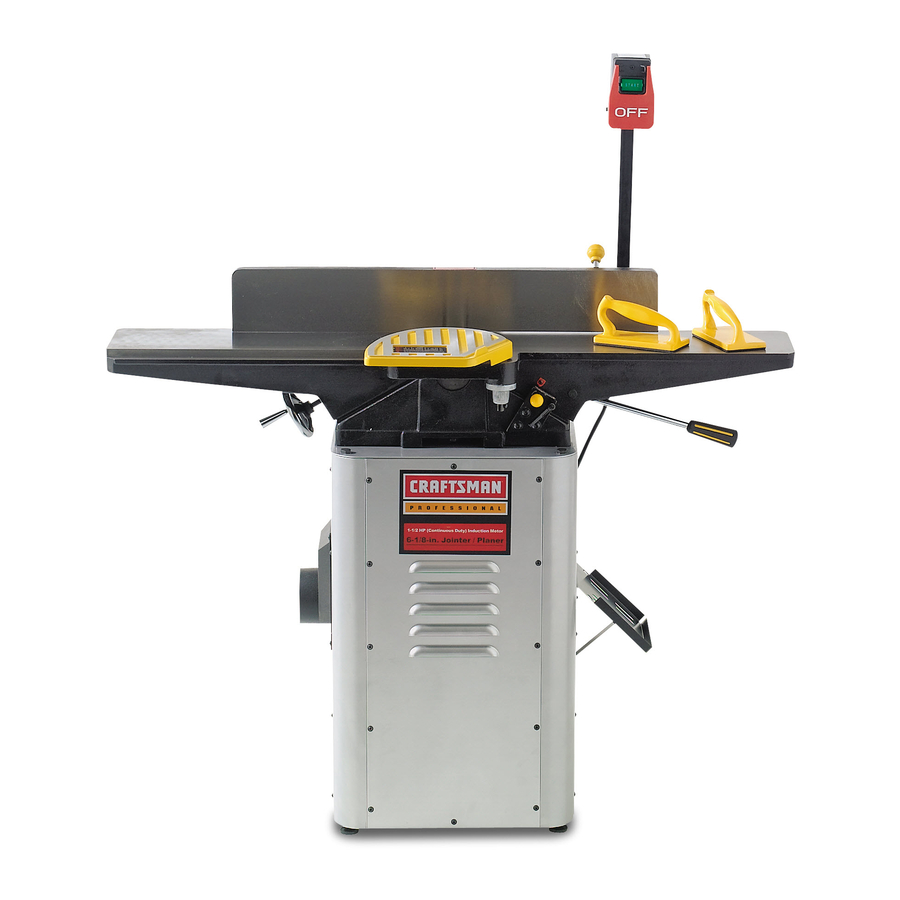
6-1/8-in. Wide
1-1/2 Horsepower
(continuous
duty)
5000 Cutterhead
R.P.M. (no load speed)
Mode_ No.
152.217050
/
C
S
FOR YOUR OWN SAFETY;
Read
and foUlow all of the Safety and
Operating
Instructions
before
Operating
this Table Saw.
Customer Helpline
1-800-897-7709
PRease have your Model No.
and SedaR No. availabUe.
Sears, Roebuck
and Co., Hoffman
Estates,
JL 60179 U.S.A.
Part No. 0R92216
EspaSoU, pg, 33
Advertisement
Table of Contents

Related Manuals for Craftsman 152.217050


Summary of Contents for Craftsman 152.217050
- Page 1 truction ® 6-1/8-in. Wide 1-1/2 Horsepower (continuous duty) 5000 Cutterhead R.P.M. (no load speed) Mode_ No. 152.217050 FOR YOUR OWN SAFETY; Read and foUlow all of the Safety and Operating Instructions before Operating this Table Saw. Customer Helpline 1-800-897-7709 PRease have your Model No. and SedaR No.
- Page 2 SECTION PAGE Warranty ................................ProductSpecifications ............................Safetyinstructions............................... Groundinginstructions ............................SpecificSafetyinstructionsfor Jointer/Ptaner ......................Accessories andAttachments ..........................CartonContents ..............................KnowYourJointer/PJaner ............................Assemblyinstructions............................Operating the JointedPtaner ..........................DustCollectionfor the JointedPtaner ........................Maintenance ................................ Troubleshooting Guide............................PartsList................................EspaSoJ ................................Service information ............................
- Page 3 GENERAL SAFETY INSTRUCTmONS ALWAYS WEAR EYE PROTECTION, Any power tooUcan throw debris into the eyes during opera- Operating a Jointer/Haner can be dangerous if safety tions, which couUd cause severe and permanent and common sense are ignored, The operator must be eye damage, Everyday eyegUasses are NOT safety familiar with the operation of the tool Read this manuaU gUasses, ALWAYS wear Safety Goggbs...
- Page 4 21. EACH AND EVERY TmME,CHECK FOR DAM- GUIDEUNES AGED PARTS PRmORTO USmNGTHE TOOL. EXTENSUON CORDS Carefully check aH guards to see that they operate The smaller the gauge-number, the larger diameter of properUy, are not damaged, and perform their the extension cord, if in doubt of the proper size of an intended functions.
- Page 5 USE ONLY A 3-WIRE EXTENSION CORD THAT HAS A 3-PRONG GROUNDING PLUG AND A 3-POLE THiS TOOL MUST BE GROUNDED WHILE iN USE RECEPTACLE THAT ACCEPTS THE TOOL'S PLUG. TO PROTECT THE OPERATOR FROM ELECTRIC REPLACE A DAMAGED OR WORN CORD IMMED- SHOCK.
- Page 6 it is aUsonecessary to repUace the 120 voUtpUug,sup- KEEP cutterhead knives sharp and free of all rust plied with the motor, with a UL/CSA Listed pUugsuitabb and pitch, for 240 voUts and rated current of the jointer/pUaner, Contact a bcaU qualified eUectdcian for proper proce- BEFORE starting machine, check cutterhead guard dures to install the pUug,The jointer/pUaner must compUy to make sure it is not damaged and operates freely,...
- Page 7 19, DONOTattempt t o perform anabnormal or little- permanent respiratory o r otherinjury, i ncluding usedoperation w ithout s tudyandtheuseofade- silicosis (a serious lungdisease), cancer, a nd quateholddown/push blocks, j igs,fixtures, s tops, death. A voidbreathing thedust,andavoidpro- pushblocks, e tc, longed contact w ithdust.Allowing dustto getinto yourmouth or eyes,or layonyourskinmaypro- 20, SHUT OFFpower before adjusting jointer,...
- Page 8 Fig. 2-1 Front panel Bottom plate Note: This panel has the Craftsman Professional Dust chute label, Push blocks (2) Back panel Dust chute port Right side panel assembly...
- Page 9 Fig. 2-2 12, Jointer a ssembly 13, Motor assembly 14, Fence 15, Fencebeveling assembly 16, Motorpulley 17, ON/OFF switchassembly 18, Cutterhead g uard 19, Infeedtablehandle 20, Fencehandles (2) 21, Rearcutterhead g uard 22, V-Belt Fig. 2-3 23, Leveling feet with hex nut (4) 24, Hex head screw 3/8-16 x 1"...
- Page 10 Fig. 3-1 1, Outfeed TaMe 10, Depth-of-Cut scaHe 2, Fence 11, Push Mocks 3, Fence Cam HockhandHe 12, Push Mock hoHder 4, Fence handHe 13, EncHosed stand 5, ThermaH reset button 14, Leveling feet 6, ON/OFF switch 15, Dust Chute Port Note: Dust Chute Port is onHy to be assembHed if a 7, Cutterhead guard dust coHHector i s to be used with this Jointer/PHaner...
- Page 11 Fig. 4-2 TO AVOmD SERmOUS mNJURY AND DAMAGE TO THE JOmNTER/PLANEFt: DO NOT assemble the Jointer/Planer until you are sure the tool mSNOT plugged in, DO NOT assemble the Jointer/Planer until you are sure the power switch is in the "OFF" position, DO NOT assemble the Jointer/Planer until you have read and understood this entire instruction Manual,...
- Page 12 Fig. 4-4 MOTOR ASSEMBLY DO NOT assemMe the Jointer/Haner until you are sure the power switch is in the "OFF" position and the power cord is disconnected from the power source, Lay the stand assemMy onto its Ueftside paneU assemMy (A) See Figure 4-4, Assemble the motor pulley (A) onto the motor shaft (B), Make sure the two set screws (C) in the motor Hace dust chute (M) in between flanges (N) of the...
- Page 13 Position the Jointer/Haner (A) onto the stand (B) so Fig. 5-3 that the three studs under the jointer's base a(ign with the three sbts in the top plate of the stand, See Figure 6-1, Secure the jointer to the stand with three MIO fiat washers, MIO bck washers and MIO hex nuts, Note: Two of the studs in the jointer base can be accessed inside of the stand, The third stud can...
- Page 14 BELT ASSEMBLY GUARD AND SWITCH ASSEMBLY DO NOT assembb the Jointer/Haner until you are sure DO NOT assembb the Jointer/Haner until you are sure the power switch is in the "OFF" position and the power the power switch is in the "OFF" position and the power cord is disconnected from the power source, cord is disconnected from the power source,...
- Page 15 FENCE ASSEMBLY DO NOT assemble the Jointer/Haner until you are sure the power switch is in the "OFF" position and the power cord is disconnected from the power source, Fig. 10-1 Loosen set screw (A) on fence bevel assembly (B) and remove the cam lock shaft (C), Remove the bolt damp (D), M12 fiat washer (E) and M12 Nylock hex nut (F) from cam lock shaft (C), See Figure 10-1,...
- Page 16 Fig. 10-5 Fig. 10-7 Assemble the M12 fiat washer (E) Figure 10-7, and M12 Nylock hex nut (F) onto the bolt clamp (D), Make sure the cam lock handle (S) Figure 10-6, is at a one o'clock position and tighten the Nyloek hex nut, This sets the locking mechanism for the fence slide, Now the fence slide should lock and unlock Reassembb...
- Page 17 CUTTERHEAD GUARD ASSEMBLY FRONT AND BACK PANEL ASSEMBLY DO NOT assembie the Jointer/Pianer until you are sure DO NOT assembie the Jointer/Pianer until you are sure the power switch is in the "OFF" position and the power the power switch is in the "OFF" position and the power cord is disconnected from the power source, cord is disconnected from the power source,...
- Page 18 CAUTION To turn the Jointer/Haner on, press the green "ON" button (B) in one-half inch. Note: There is a safety • Aseparate eUectdcaU circuit s houUd be usedforyour feature on the switch to insure that the switch must Jointer/Haner. TheJointer/Haner comespre-wired f or 120-voUt use.Thecircuit s houUd notbe Uess than#14 be completely pressed before the motor will start.
- Page 19 THERMAL°OVERLOAD PROTECTION CAUTION: 1/2" DEPTH-OF-CUT iS ONLY USED iN RABBET-CUTTING OPERATIONS. After the depth-of-cut is set, tighten the infeed table Turn the power switch OFF and unplug the power lock handle (A), See Figure 14=1, cord from its power source prior to performing any maintenance or adjustments, The pointer (C) on the depth-of-cut scab (D) Make certain that the OFF button has been depressed...
- Page 20 Standing in front of the jointer, grasp the top of the fence between the front support brackets (C) and slide the fence to the desired position, Tighten cam handle, Make sure the cutterhead guard (D) returns and rests against the fence, If not see CUTTERHEAD GUARD ASSEMBLY section in assembly instruction for setup procedure,...
- Page 21 45 Degree Out Positive Stop Adjustment 45 Degree in Positive Stop Adjustment Fig. 17-2 Fig. 17-3 To set fence 45 degree in to the table surface, first make sure the 90 degree stop knob (A) is pulled out. See Figure 17o3. Loosen the bevel lock handle (D) and tilt the fence forward and against the 45 degree in positive stop To set fence 45 degree out to the tame surface, first...
- Page 22 KNIFE ADJUSTMENTS Fig. 18-2 in order to do accurate work, the knives must be exactly bveU with the outfeed tame. See Figure 18-1. Fig. 18-1 if a knife (D) is low, turn knife locking screws (G) clockwise one half turn with an 8mm open end wrench (not included), CAUTION: The knives are very sharp;...
- Page 23 KNIFE REMOVAL KNIFE REPLACEMENT CAUTION: To avoid cutting yourself, be very careful when removing, replacing and resetting knives, Fig. 19-1 1/16" of Knife Protrusion from Cutterhead 1/16" To avoid serious injury, disconnect jointer/planer from power source. CAUTION: The knife edges are sharp. Do not touch or you may be cut.
- Page 24 ADJUSTING TABLE GUBS CHANGUNG MOTOR VOLTAGE Gibs are internai mechanisms that take up any piay between the base and the infeed and outfeed tames. MAKE CERTAIN the Jointer/Haner is disconnected Precise gib adjustment is done at the factory and shouid not require any further adjustments. However, from the power source before working on motor.
- Page 25 Useofthistoolcangenerate anddisburse dustor other Jointing and planing operations generate large amounts airborne particles, including wooddust,crystalline s ilica of wood chips and dust, A dust collection system is rec- dustandasbestos dust,Direct p articles awayfromface ommended for your Jointer/Planer, Provided with your andbody, A lways operate toolinwellventilated area Jointer/Planer is a dust chute port with a 4"...
- Page 26 Repairs to theJointer/Planer shouldbeperformed b y tenance to keep your table saw looking new, Cleaning trained personnel only,Contact y ournearest S ears and waxing the cast iron surfaces on a regular main- Service Center f orauthorized s ervice, U nauthorized tenance schedule is recommended as follows: repairs or replacement withnon-factory p artscould...
- Page 27 TOPREVENT i NJURY TOYOURSELF o r damage to theJointer/Haner, turntheswitchtothe"OFF" position and unpUug thepower cordfromtheeUectdcaU receptacle b efore making anyadjustments, PROBLEM SOLUTION UKELY CAUSE(S) Motor does not 1. Switch not pressed in far enough Depress switch in 1/2 inch or make sure switch is in the start switch in the "OFF"...
- Page 28 6-1/8qN. JOmNTER/PLANER PARTS UST MODEL NO. 152.217050 When servicing, use only CRAFTSMAN replacement parts, Use of any other parts may create a HAZARD or cause product damage, Any attempt to repair or replace electrical parts on this Jointer/Planer may create a HAZARD unless repair is done by...
- Page 29 6-1/8-mN. JOmNTER/PLANER PARTS LmST MODEL NO.152.217050 PART PART DESCRIPTION QTY, DESCRIPTION QTY, HEX NUT M8 STD840610 HEX NUT M8 STD840812 STD523710 HEX HEAD SCREW 3/8-!6 x 1" OR93458 SLIDE ASSEMBLY; (NOT SHOWN) (CONSISTS OF REF#'S !07, !08, !09, 110, !11, STD833012 HEX HEAD SCREW M6 x 12mm 112, 113, 1!4, 118, 119, 120_ 12!_ 122_ 123_ 124,...
- Page 30 6-1/8qN. J OmNTER/PLANER PARTS UST MODEL NO.152.217050 90 --I...
- Page 31 6-1/8qN. JOINTER/PLANER PARTS UST MODEL NO. 152.217050 i 32...
- Page 32 6-1/8qN. J OmNTER/PLANER PARTS UST MODEL NO.152.217050 193 _/ 197_...
- Page 33 ® 6ol/8 pumg. de ancho 1o1/2 cabalio de fuerza (servicio continuo) Cabezam de corte de 5000 R.P.M. (sin vemocidad de carga No. de Mode_o 152.217050 PARA SU SEGURIDAD PERSONAL; Lea y obedezca todas las lnstrucciones Seguddad y Funcionamiento antes de accionar esta MacNmbradora/Cepilladora.
- Page 34 SEOCION PAGINA Garantia ..................................... Especificaciones del Producto ............................lnstrucciones de Seguddad ............................lnstrucciones de Cone×i6n a Tierra ..........................lnstrucciones de Seguddad Especfficas para Machimbradoras/Cepiltadoras ............Accesorios y Cone×iones ..............................Contenido de ta Caia ................................ Conzoca su Machimbradora/Cepiltadora ........................lnstrucciones de Montaje ..............................Accionando la Machimbradora/Cepiltadora ........................
- Page 35 INSTRUCCIONES GENERALES UTIUCE PROTECCION OCULAR S_EMPRE. Cualquier herramienta mecanica puede expulsar escombros hacia DE SEGURIDAD los ojos durante las operaciones, resultando en daflo El funcionamiento de una Machimbradora/Cepilladora puede ocular grave y permanente. Los anteojos cotidianos NO resultar peligroso si se hace caso omiso de la seguridad y del son gafas de seguridad.
- Page 36 21: REVISE SI HAY PIEZAS DANADAS ANTES DE OADA DIRECTRICES PARA USO DE LA HERRAMIENTA. Revise todos los protec- LAS EXTENSUONES ELECTRICAS tores cuidadosamente para comprobar que funcionan correctamente y que no estan dahados, y que reatizan Mientras menor sea eI n0mero de calibre, mayor sera el sus funciones diseSadas correctamente.
- Page 37 USE SOLO UNA EXTENSKSN EL¢:CTR_CA DE TRES HJLOS CON ENCHUFE DE CONEXJON A TIERRA DE TRES MACNOS Y RECEPTACULO DE TRES MACNOS QUE ESTA HERRAM_ENTA DEBE ESTAR CONECTADA ACEPTE EL ENCNUFE DE LA NERRAMIENTA. TIERRA DURANTE EL USO PARA PROTEGER AL OPERAR_O CONTRA LOS CHOQUES ELC;CTR_COS.
- Page 38 Tambien resulta necesario reemplazar el enchufe de 120 MANTENGA las cuchilIas del cabezal de corte afiladas y voltios suministrado con el motor por un enchufe de clasifi- libres de moho y alquitrb, n. caci6n UL/CSA adecuado para el funcionamiento a 240 voItios y Ia corriente clasificada de Ia machimbradora ANTES de arrancar la maquina, revise el protector det cepilIadora.
- Page 39 19. NO trate de realizar una operaci6n anormal o poco [ncluyendo silicosis (una enfermedad pulmonar grave), utilizada sin e! estudio debido y e! uso de retenes/ cancer y la muerte. Evite aspirar el polvo y evite el con- bloques de empuje, montaje, fi]aciones, topes, etc. tacto prolongado con el polvo.
- Page 40 Fig. 2-1 Panel delantero Placa inferior Aviso: este panel JJevaJaetiqueta Craftsman Conducto de poJvo Professional. BIoques de empuje (2) Panel trasero Puerto del conducto de polvo Ensamblado...
- Page 41 Fig. 2-2 12. EnsambIado de machimbradora 13. EnsambIado del motor 14, Gufa 15. Ensamblado de biselado de la gu[a 16. Polea del motor 17. Ensamblado del interruptor de ENCENDDO / APAGADO 18. Protector del cabezal de corte 19. Asidera de Ia mesa de avance directo 20.
- Page 42 1. Mesa de avarice de salida 10. Escala de profundidad de corte 2, Gu[a 11. Bloques de empuje 3. Agarradera de cierre de la desiizadera de la gufa 12. Portador de bloque de empuje 13. Estante encerrado 4. Agarradera de la gu(a 5.
- Page 43 Fig. 4-2 PARA EVJTAR HERJDAS GRAVES Y DANO A LA MACHII_- BRADORA 1 CEPILLADORA: NO monte !a machimbradora / cepii!adora hasta que este seguro de que la herramienta NO esta enchufada. NO monte !a machimbradora / cepiHadora hasta que este seguro de que eI interruptor de energfa se encuentre en la posici6n de "APAGADO".
- Page 44 Fig. 4-4 ENSAMBLADO DEL MOTOR NO monte Ia Machimbradora/Cepilladora hasta que este seguro de que el interruptor de energ[a se encuentre en la posici6n de APAGADO y el cord6n de energ[a este desconec- tado de la fuente de energ[a. Coloque el ensamblado del estante sobre su ensamblado det panel lateral izquierdo (A).
- Page 45 Co!oque la Machimbradora / Cepilladora (A) sobre el Fig. 5-3 estante (B) de manera que los tres gorrones situados per debajo de la base de Ia machimbradora queden alinea- dos con las tres ranuras en la placa superior deI estante. Ver la Figura 6-1.
- Page 46 ENSAMBLADO DE LA CORREA ENSAMBLADO DEL PROTECTOR EL INTERRUPTOR NO monte la Machimbradora / Cepilladora hasta que este NO monte Ia Machimbradora / Cepilladora hasta que este seguro de que el interruptor de energ[a se encuentre en Ia seguro de que el interruptor de energ[a se encuentre en la posici6n de APAGADO y eI cord6n de energ(a este desconec- posici6n de APAGADO y el cord6n de energ[a este desconec- tado de la fuente de energ[a.
- Page 47 ENSAMBLADO DE LA GUiA Fig. 10-3 NO monte la Machimbradora / Cepilladora hasta que este seguro de que el interruptor de energfa se encuentre en Ia posici6n de APAGADO y eI cord6n de energfa este desconec- tado de la fuente de energfa. Fig.
- Page 48 Fig. 10-5 Fig. 10-7 °E 10+ Monte Ia arandeta plana M12 (E, Figura 10-7) y Ia tuerca hexagonal Nylock M12 (F) a la abrazadera de pernos (D). Aseg0rese de que la agarradera del cierre de Ievas (S, Figura 10-6) este en la posici6n de 1:00 y luego apriete la tuerca hexagonal Nytock.
- Page 49 ENSAMBLAJE DEL PROTECTOR ENSAMBLAJE DE LOS PANELES CABEZAL DE CORTE DELANTERO Y POSTERIOR NO monte la Machimbradora / Cepilladora hasta que este NO monte Ia Machimbradora / CepiIladora hasta que est6 seguro de que el interruptor de energfa se encuentre en Ia seguro de que el interruptor de energfa se encuentre en la posici6n de APAGADO y el cord6n de energ[a este desconec- posici6n de APAGADO y el cord6n de energfa este desconec-...
- Page 50 PRECAUCI6N Para encender Ia Machimbradora / CepilIadora, oprima el bot6n verde de ENCENDIDO (B) una mitad de pulgada. Debe utilizar un circuito electrico aparte para su Aviso: Existe un distintivo de seguridad en el interruptor Machimbradora / Cepilladora. La Machimbradora para asegurar que el interruptor sea oprimido completa- Cepilladora viene cableada de antemano para el uso a mente antes de que pueda arrancar el motor.
- Page 51 PRECAUCI6N: LA PROFUNDIDAD DE CORTE DE 1/2 PROTECCION CONTRA PULG° SOLO SE UTIUZA EN LAS OPERACIONES SOBRECARGAS TERMICAS CORTE DE ALEFRJZ° Una vez fijada la profundidad de corte, apriete la asidera de enclavamiento de la mesa de alimentaci6n (A). Gire el interruptor de energfa a la posici6n de APAGADO Ver Figura 14-1.
- Page 52 De pie frente a Jamachimbradora, agarre Ia parte superior de la gufa entre los soportes de apoyo delanteros (C) y deslice Ia gufa a Ia posici6n deseada. Apriete Ia agarradera de levas. AsegOrese de que el pro- tector deJ cabezal de corte (D) regrese y descanse contra la gufa.
- Page 53 Ajuste de Parada de 45 Grados Positivos A]uste de Parada de 45 Grados Positivos hacia Afuera hacia Adentro Fig. 17-2 Fig. 17-3 Para fijar Ia gu[a a 45 grados hacia adentro contra Ia superficie de Ia mesa, aseg0rese primero de que se haya extra(do Ja perilla de parada de 90 grades (A).
- Page 54 AJUSTES DE CUCHILLAS Fig. 18-2 Para poder reaHzar un trabajo certero, Has cuchHHas deben estar niveHadas exactamente con Hamesa de avarice de saHda. Ver Figura 18-1. Fig. 18-1 S[ una cuchiila (D) se encuentra baja, gire los tornillos de enclavamiento de cuchiIIas (G) en el sentido de las agu- jas deI reIoj una mida de vuelta con una IIave de boca de 8 mm (no incluida).
- Page 55 EXTRACCK)N DE CUCHILLAS REEMPLAZO DE CUCHILLAS PRECAUClON: Para prevenir cortaduras, se debe tener Fig. 20-1 cuidado ai quitar, reempJazar y recolocar las cuchiJJas. Fig. 19-1 1/!6 putg. de proyecci6n de tas cuchittas del cabezal de corte 1/16" Para prevenir heridas graves, desconecte la machimbradora/ cepilladora de Jafuente de energ[a.
- Page 56 AJUSTANDO LAS CORREDERAS CAMBIANDO EL VOLTAJE DEL MOTOR DE AJUSTE Las correderas de ajuste con mecanismos internes que elimP ASEGURESE de que la Machimbradora / Cepilbdora nan cualquier holgura que pueda existir entre la base y Ias este desconectada de la fuente de energfa antes de mesas de alimentaci6n y avance de salida.
- Page 57 El use de esta herramienta puede generar y dispersar polvo u Las operaciones de machimbrado y cepillado generan otras part[culas aereas, incluyendo polvo de madera, polvo grandes cantidades de astillas de madera y polvo. Se de sflice cristalino y polvo de asbesto. Aleje las part[culas del recomienda el use de un sistema de recolecci6n de polvo con rostro y deI cuerpo.
- Page 58 Las reparaciones a Ia Machimbradora/Cepilladora deben ser mantenimiento rutinario para conservar su sierra de mesa realizadas por personal capacitado solamente. Comunfquese come nueva. Se recomienda Ia Iimpieza y el encerado de las con su Centre de Servicio Sears mas cercano para el servicio superficies de hierro moldeado conforme aI siguiente progra- autorizado.
- Page 59 PARA PREVENJR LAS HERIDAS A Si MISMO o eI daSo a la machimbradora/cepiiladora, gire el interruptor a la posici6n de "APAGADO" (OFF) y desenchufe el cord6n de energ(a del tomacordentes antes de realizar cualquier ajuste= PROBLEMA CAUSA 0 CAUSAS PROBABLES SOLUCt6N El motor no arranca...
- Page 60 Your Home 'i'i'i'i'i'i'i'i'i'i'i'i'i'i'i'i'i For repair-in your home-of all major brand appliances, iiiiiiiiiiiiiiiiiii iiiiiiiiiiiiiiiiiii iiiiiiiiiiiiiiiiiii lawn and garden equipment, or heating and cooling systems, iiiiiiiiiiiiiiiiiii iiiiiiiiiiiiiiiiiii no matter who made it, no matter who sold it! iiiiiiiiiiiiiiiiiii iiiiiiiiiiiiiiiiiii iiiiiiiiiiiiiiiiiii For the replacement parts, accessories iiiiiiiiiiiiiiiiiii iiiiiiiiiiiiiiiiiii...