Table of Contents
Advertisement
Available languages
Available languages
perator_s
nual
I:RRF rSMRN °
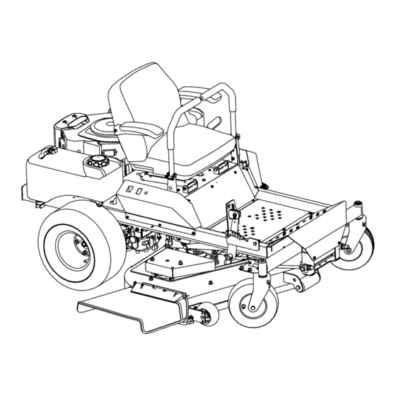
ZERO=TURN
RIDER
27 Hi:), 48" MOWER DECK
Model No. 247,25003
CAUTION:
Before
using this product,
read this manual
and follow
all safety
rules and operating
instructions,
,
SAFETY
ASSEMBLY
OPERATION
MAINTENANCE
PARTS LIST
o ESPANOL
Sears Brands
Management
Corporation,
Hoffman
Estates,
IL 60179, U.S.A.
Visit our website:
www.craftsman.com
FormNo.769-07656
(November7,2011)
Advertisement
Table of Contents

Related Manuals for Craftsman 247.25003


Summary of Contents for Craftsman 247.25003
- Page 1 Model No. 247,25003 SAFETY ASSEMBLY OPERATION MAINTENANCE PARTS LIST CAUTION: Before using this product, o ESPANOL read this manual and follow all safety rules and operating instructions, Sears Brands Management Corporation, Hoffman Estates, IL 60179, U.S.A. Visit our website: www.craftsman.com FormNo.769-07656 (November7,2011)
-
Page 2: Warranty & Service
(our testingprovesthat it will nothold a charge).A defectivebatterywill receivefree in-homereplacement. WARRANTYSERVICE Forwarrantycoveragedetails to obtainfree repairor replacement, c all 1-800-659-5917 or visitthe website: www.craftsman.com In all casesabove,if part repairor replacement i s impossible, t he ridingequipmentwill be replacedfreeof chargewith the sameor an equivalent model. -
Page 3: California Proposition
This machinewas builtto be operatedaccordingto the safeopera- This symbolpointsout importantsafetyinstructionswhich,if not tion practicesin this manual.As with anytype of powerequipment, followed,couldendangerthepersonalsafetyand/orpropertyof carelessnessor error on the partof the operatorcan resultin serious yourselfand others. Readand followall instructionsin this manual injury.This machineis capableof amputatingfingers,hands,toes beforeattemptingto operatethis machine.Failureto complywith and feet and throwingdebris.Failureto observethe followingsafety these instructionsmay resultin personalinjury.Whenyou seethis... -
Page 4: Slope Operation
SLOPE OPERATION • Use extracare whenloadingor unloadingthe machineintoa traileror truck. This machineshouldnot be drivenup or down Slopesare a majorfactorrelatedto loss of controland tip-over ramp(s),becausethe machinecouldtip over,causingserious accidentswhichcan result in severeinjuryor death.All slopes require personalinjury.The machinemustbe pushedmanuallyon extra caution.If youcannot back up the slopeor if youfeel uneasyon ramp(s)to loador unloadproperly. - Page 5 CHILDREN SERVICE Tragicaccidentscanoccur ifthe operatoris notalert to the presence SafeHandlingof Gasoline of children.Childrenare often attractedto the machineand the mowing Toavoidpersonalinjury or propertydamageuse extremecarein activity.They do notunderstandthe dangers.Neverassumethat handlinggasoline.Gasolineisextremelyflammableand the vaporsare childrenwill remainwhereyou last sawthem. explosive.Seriouspersonalinjury canoccur whengasolineis spilled • Keepchildrenout of the mowingareaand inwatchfulcare of a on yourselfor your clotheswhich can ignite.Washyourskin and responsibleadultotherthanthe operator.
- Page 6 • Check theblade(s) and engine mounting bolts a tfrequent DO NOT MODIFY ENGINE intervals forproper tightness. Also, visually inspect blade(s) for Toavoid seriousinjuryor death,do notmodifyengine in anyway. damage (e.g., excessive wear, bent, cracked). Replace the Tampering with the governorsettingcanlead to a runaway engineand blade(s) with the original equipment manufacturer's (O.E.M.)
- Page 7 SAFETY SYMBOLS This pagedepictsand describessafety symbolsthat may appearon this product. Read,understand,and follow all instructions on the machine beforeattemptingto assembleand operate. READTHE OPERATOR'S MANUAL(S) Read,understand,and followall instructionsin the manual(s)beforeattemptingto assembleand operate WARNING-- ROTATING BLADES Donot put handsor feet near rotatingpartsor underthe cuttingdeck.Contactwith the blade(s)can amputatehandsand feet.
- Page 8 15° Slope 15° Slope (OK) (TOO STEEP) '_. _ Figure 1 Figure 2 15° dashed line USETHISSLOPE GAUGE TODETERMINE IF A SLOPE IS TOOSTEEPFORSAFEOPERATION! To checkthe slope, proceedas follows: Removethis pageand fold along the dashedline. Locatea verticalobject on or behindthe slope (e.g. a pole, building,fence, tree, etc.) 3.
- Page 9 RiDiNG MOWER PREPARATION Removethe two shoulderbolts and lock nuts in the seatpan as shown in Figure2. Removethe uppercratingmaterialfrom the shippingpallet,and cut anybandsor tie strapssecuringthe riding mowerto the pallet. Use the lift handleto raisethedeck to its highestposition. Fromjust in front of thetwo rear tires,locatethe transmission bypassrods.Referto Figure1.
- Page 10 10. Installlanyardusingexistingself-tappingscrew.See Figure4. Fromthe outside,insertthe bolts throughthe hourglassspacers and the holesof the pivot bracket.Securewith theflange lock nuts.See Figure6. Figure 4 NOTE: Insertself-tappingscrewthroughhole in lanyardand downinto Figure 6 the samehole that it was removed from. Refer to"Adjusting t heDriveControl Levers" i n theService and Mainte- Position Drive Control levers...
- Page 11 Removethe plasticcover,if present,fromthe positivebattery Checking and adding terminaland attachthe redcableto the positivebatteryterminal NOTE: Yourriding moweris shippedwith oil inthe engine.However, (+)with the bolt and hexnut. See Figure7. you MUSTcheckthe oil levelbeforeoperating. Placethe riding moweron a flat,levelsurface. Removethe oil filler cap/dipstickand wipe thedipstickclean. See Figure9.
- Page 12 Storage Tray Cup Holder Fuel Shut=Off Valve RH Drive Control Lever Deck Lift LH Drive Control Lever PTOSwitch Deck Height index Hour Meter ignition Switch Figure10 DECK LiFT PEDAL Nowthat youhaveset up yourridingmower,it's importantto become acquainted with its controlsand features.Referto Figure10. The deck lift pedalislocatedon the rightfront cornerof the foot NOTE: References to LEFT,RIGHT,FRONT, a nd REARindicatethat platform,and isusedto raiseand lowerthe mowerdeck.
- Page 13 PARKING BRAKE ENGAGEMENT LEVER iGNiTiON SWITCH Theignitionswitchis locatedon the RH consoleto the rightof the I @ITI operator'sseat.Theignitionswitch hasthree positionsas follows: STOP6 -- Theengine and electri- cal systemis turnedoff. The parkingbrakeengagement l everis locatedon the LHconsoleto the left of theoperator'sseat,and whenpulled to the rear,ENGAGES RUN_ -- Theriding mowerelectricalsystemisenergized.
-
Page 14: Seat Adjustment
SEAT ADJUSTMENT LEVER (NOT SHOWN) General Safety • RECEIVEINSTRUCTION -- Entirelyreadthis operator'smanual. The seatadjustmentleveris locatedbelowthefront/leftof the seat. Learnto operatethis machineSAFELY. D o not risk INJURYor The leverallowsfor adjustmentof the foreto aft positionof the DEATH. A llowonlythose who havebecomecompetentin its operator'sseat.Referto the Serviceand Maintenancesectionfor usageto operatethis ridingmower. -
Page 15: Safety Interlock System
SAFETY INTERLOCK SYSTEM • Slowdownbeforeturningand come toa completestop before anyzeroturn maneuver. • This ridingmoweris equippedwith a safety interlocksystemfor • If youhit a solidobject whilemowing,DISENGAGE the PTO, the protectionof the operator.If the interlocksystemshouldever placethe steeringleversin the neutral,opened-outposition, malfunction, d o not operatethe ridingmower.Call 1-800-659- movethe throttleto slowq?::>,set the parkingbrake8, shut off 5917to scheduleservicefrom SearsParts &... -
Page 16: Starting The Engine
STARTING THE ENGINE Turnthe ignitionkey clockwiseto the START_ positionand releaseit as soonas the enginestarts; however, d o notcrank the enginecontinuouslyfor morethan 10secondsat a time. Ifthe This ridingmoweris equippedwith a safetyinterlock s ystem enginedoes not startwithinthis time,turnthe key to STOP designedforthe protectionof the operator.Do notoperatethe riding and wait at least 30 secondsto allowthe engine'sstartermotor mowerif any partof the interlocksystemis malfunctioning. -
Page 17: Driving The Riding Mower
DRIVING THE RIDING MOWER Stopping the Engine Pushthe PTOswitchdownintothe DISENGAGED position. Movethe RH and LH drivecontrolleversoutwardto the neutral Avoidsuddenstarts,excessivespeedand suddenstops. position. Adjust theoperator'sseat to the mostcomfortablepositionthat Engagethe parkingbrakeO. allowsyou to operatethe controls.See seatadjustmentin the Movethe throttlecontrol to midwaybetweenthe SLOW_ Assemblysection. FAST_ positions. - Page 18 Driving the Riding Mower Forward Turning the Riding mower While Driving Forward Keepall movement o f the drivecontrolleversslow and smooth. When reversing the directionof travel,we recommendperforming Abruptmovement o f the controlleverscan affectthe stabilityof the gradual'U turns wherepossible.Sharperturns increasethe possibil- ridingmowerand couldcausethe ridingmowerto flip over,which ity of turf defacement,and couldaffect controlof the ridingmower.
- Page 19 NOTE:The greaterthe fore-to-aftdistancebetweenthe two levers,the Turning While Driving Rearward sharperthe riding mowerwill turn. Toturn the riding mowerwhiledriving rearward, m ovethe control Toexecutea "zeroturn,"movethe turnside drivecontrolleverto leversas necessaryso that one leverisforwardof the other.Theriding mowerwill turn inthe directionof the forwardcontrol lever. the neutralposition,while movingthe othercontrolleverforward. NOTE: Makinga "zeroturn"on grasswill greatlyincreasethepotential Toturn to the left whiletravelingin reverse,movethe left drive for defacement o f the turf.
-
Page 20: Driving On Slopes
Executing a Zero Turn Executing a "Y" Manuever Forlowtractionconditions,followthese procedures for zeroturns (the "Y-manuever"): Whenexecutinga zeroturn, the ridingmowerMUSTBE STOPPED. Toturn clockwise(front of machinemovestowardRIGHT)when Executinga zeroturn whilethe ridingmoweris movingcan signifi- travelingFORWARD: Icantlyreduceyourcontrol of the ridingmowerand will causesevere [turf defacement t o occur. Cometoa stop, Then slowlymove bothcontrolleversrearward(no morethan 1/2 Stopthe forwardor reversemotionof the riding mowerby moving... -
Page 21: Operating The Pto
OPERATING THE PTO To preventruttingor groovingof the turf, ifpossible,changethe directionthat the stripsare mowedby approximately 450forthe Operatethe PTOclutchasfollows: nextand each subsequentmowing. Movethe throttlecontrol leverto approximately the midthrottle position. Becareful whencrossinggravelpaths or driveways.Disengagethe Pull the PTOswitchupwardto the ENGAGED position. PTOand raisethe deck to the highestpositionbeforecrossing. Advancethe throttleleverto the FAST_ position. -
Page 22: Maintenance
MAINTENANCE SCHEDULE Followthe maintenanceschedulegivenbelow.This chart describes serviceguidelinesonly. Usethe ServiceLog columnto keeptrackof Beforeperforming any type of maintenance/service, disengageall completedmaintenance tasks.To locatethe nearest Sears Service controlsand stop the engine.Wait untilall movingpartshavecome Centeror to scheduleservice,simplycontactSears at to a completestop.Disconnectspark plugwire and groundit against 1-800-4-MY-HOME®. -
Page 23: Oil Chart
OIL CHART Applya few dropsof SAEengine oil,grease,or usea spraylubricant.Applythe oil to bothsides of pivot points.Wipeoff anyexcess.Startengine and operatemowerbrieflyto insurethat oil spreadsevenly. Number of Oil Points Description DALLY DeckSuspensionPivots HeightAdjustmentTurnbuckleClevisPin HeightAdjustmentHandlePivots HeightAdjustmentStopPivots Deck Lift LinkagePivots TransportHandlePivots TransportHandlePin Deck FrameUp-and-DownPivots WEEKLY SeatHinge SteeringLeverLinkageRod EndBearings LeverReturnAssemblyRodEnd Bearings PumpControlLeverPivots... -
Page 24: Engine Maintenance
Locatethe oil drainhoseon the engine.See Figure23. Before performing any maintenance orrepairs, disengage the PTO, move t he drive c ontrol levers fully outward inthe neutral position, Iengage the parking brake, stop the engine and remove the key to [prevent unintended starting. - Page 25 Cleanthearea aroundthe oil filter. Placea containerunderthe Removethepre-cleaner. filter to catchanyoil and removethe filter.See Figure24. Replaceor washthe pre-cleanerin warmwaterwith detergent. Rinsethoroughlyand allowthe pre-cleanerto air dry. Hookthe latchand close the accessdoor. Air Cleaner Openthe air cleaneraccess doorand unhookthe latch.See Figure25. Removethe air cleanerand pre-cleanerfrom the base. Servicethepre-cleaneras instructedabove.
- Page 26 Measurethe plug gap with a feelergauge.Correctas necessary Fuel Filter by bendingthe side electrode,Figure27.The gap shouldbe set to .02-.03inches (0.60-0.80ram). Gasolineand its vaporsare extremelyflammableand explosive.Fire or explosioncancause severeburnsor death. • Keepgasolineawayfrom sparks,openflames,pilot lights,heat, and other ignitionsources. • Checkfuel lines,tank,cap, and fittings frequentlyfor cracks Electrode or leaks.Replaceif necessary.See a Searsor otherqualified servicedealerto replacefuel line.
-
Page 27: Hydrostatic Transmission
HYDROSTATIC TRANSMiSSiON GENERAL BATTERY INFORMATION Yourzeroturntractoris equippedwith dual integratedhydrostatic pumps/transaxles that are sealedand are maintenance-free. However, Should batteryacid accidentally splatterintothe eyesor ontothe this modelis equippedwitha transmissionoil expansionreservoir. skin, rinsetheaffectedarea immediately with cleancold water.If Undernormaloperatingconditions,the oil levelin the expansion there isany furtherdiscomfort,seekpromptmedicalattention.If acid reservoirdoes not needto be checkedand no additionaloil is needed. -
Page 28: Tire Maintenance
Charging the Battery TIRE MAINTENANCE Test and, i fnecessary, recharge the battery after t he tractor has been Checkthe tireair pressurebeforeeachuse. Inflationpressureof the stored foraperiod oftime. reartires is importantfor stabilitywhilethe moweris in operation.If the tire diameteris notequal betweenthe two tires,the mowerwill pull •... -
Page 29: Using The Transmission
4. Turn o nthe water supply. ADJUSTMENTS 5. From the tractor operator's seat, start the engine and e ngage the PTO. Adjusting RH & LH Drive Control Levers Allow t orun as needed. Disengage the PTO and stop t he engine. The RH and LH drivecontrolleverscan be adjustedup or downand 6. - Page 30 Toadjustthe front-to-rearangleof the control levers: Measurethe blade-to-ground heightat the rightrear bladetip. Again be sureto measureat the bladetip at the rear of the right Loosenthe nuts on the controllevermountingbolts, leavingthe blade whenalignedalongthe mowercenterline.The blade-to- bottomone fairly snug. Thebottomhole is slotted,allowingthe ground heightat the rear of the bladetip shouldbe approximately controlleverto pivoton the top bolt.
- Page 31 Deck Removal Adjusting the Gauge Wheels Keephandsand feet awayfrom the dischargeopeningof thecutting The mufflerat the rearofthe tractormaybe extremelyhot,and could I deck. Icauseseriousburns.Useextremecautionwhennearthe muffler. A llowI _themufflertofully coolbeforeremoving thebeltfrom thePTOpulley. J NOTE:The deckgaugewheelsare an anti-scalpfeatureof thedeckand are notdesignedto supporttheweightof thecuttingdeck. Removethe mowerdeckfrom the tractoras follows: Themowerdeck cuttingheightcanbe set usingthe tractor'sdeck lift Applythe parkingbrake.Removeignitionkey and bothspark plug pedal.Thedeck heightsrangefrom 1"to 4".Thedeck gaugewheel...
- Page 32 Removethe bladedrive beltfrom all the pulleys. Removethe four hair pinsfrom the rightand left sideof the deck lift bracket.See Figure37. Reversethe processto install the belt. See Figure39 for proper belt routing. Deck Lift Bracket Hair Pin Hair Pin Figure37 Figure39 Shift the deckforward untilthe trailinglinkisfree and youare able to removethe deck.
-
Page 33: Changing The Transmission
Replacing the Blades Replaceany bladewith severenicksor dents that cannotbe removedbyfiling. Checkthe balanceof the bladeafter sharpeningby placingit on a Before performing any maintenance, place t he PTO switch inthe "OFF" bladebalancer.Do not useunbalancedblades. position,engagethe parkingbrakelever, t urnthe ignitionkeyto the If the blade dipson one end, file stockoff of the cuttingsurfaceon "OFF"positionand remove the keyfromthe switch.Protectyourhands that end. -
Page 34: Tractor Storage
Neverstoregardentractorwith fuel in tank indoorsor in poorly ventilatedareaswherefuel fumesmay reachan openflame,spark, or pilot lightas on a furnace,water heater,clothesdryer,or gas appliance. TRACTOR STORAGE Cleanthe engineand the entiretractorthoroughly. NOTE:Use of a pressurewasheror garden hoseis not recommended If yourtractoris notgoing to be operatedfor an extendedperiodof to clean yourtractor.They maycause damageto electricalcompo- time (thirtydays to approximately six months),the tractorshouldbe nents,spindles,pulleys,bearingsor theengine.The useof waterwill... -
Page 35: Need More Help
Beforeperforming anytypeof maintenance/service, disengage all controls and stoptheengine.Waituntilall moving partshavecometo a complete stop.Disconnect sparkplugwireandgrounditagainstthe I engine to prevent u nintended starting. A lways wearsafety glassesduring l operation or whileperforming anyadjustments o r repairs. Thissectionaddresses minor service issues.To locate the nearest Sears Service Centeror to scheduleservice,simplycontactSears at 1-800-4-MY-HOME®. - Page 36 Engineoverheats Engineoil levellow Fillenginewith properamountand type of oil. Air flow restricted Cleangrass clippingsand debrisfrom aroundthe engine'scoolingfins and blowerhousing. Enginehesitatesat high RPMs 1. Sparkpluggap settoo close Removesparkplug and adjustgap. Engineidles poorly Fouledspark plug Replacesparkplug and adjustgap. Dirtyair cleaner Cleanor replaceair cleanerelementand/orclean pre-cbaner.
- Page 38 Craftsman Zero=Turn Rider B IViodel No. 247.25003 "4 14--...
-
Page 39: Greasefitting
Craftsman Zero=Turn Rider B IViodel No. 247.25003 00006168 FlatWasher,3/8 00022560 i FlangeLock Nut,3/8-16 712-0290 NylockNut,7/16-14 00060078 GreaseFitting, 1/4-28x 3/16 00061053 i Washer,3/8 01000199 ExtensionSpring,1.00x 5.00 01000308 BearingSleeve 738-3108 ShoulderBolt 01003269 i FlatWasher,7/16x 1.75 01008539P i U-Nut, 1/4-20 02002628 BronzeBushing,.875x 1.50... - Page 40 Craftsman Zero=Turn Rider B Model No. 247.25003 0000...
- Page 41 Craftsman Zero=Turn Rider B Model No. 247.25003 00011925 Hex CapScrew,3/8-16x 4.00 00013406 i Hex CapScrew,5/16-18x 3/4 00022560 i FlangeLock Nut,3/8-16 712-3004A i FlangeLock Nut,5/16-18 01009872 Spacer,.370ID x .500x 3.45 02002952 i Bumper, 2 .50 x 1.13 02002960- Foot RestBracket 0637...
- Page 42 Craftsman Zero=Turn Rider B IViodel No. 247.25003...
- Page 43 Craftsman Zero=Turn Rider B IViodel No. 247.25003 00008495 Hex Screw,3/8-16x 1.75 00011438 Hex Screw,3/8-16x 1.50 00013416 Hex Screw,1/4-20x 1.00 00021956 i HairPin,3/8 x 1.562x .080 00022560 i FlangeCounterLock Nut,3/8-16 00083192 i Washer,.390x 1.00x .180 912-3027 i FlangeTopLock Nut, 1/4-20 01003468 Spacer,.375x .500x .750...
- Page 44 Craftsman Zero=Turn Rider B IViodel No. 247.25003...
- Page 45 Craftsman Zero=Turn Rider B IViodel No. 247.25003 00012166 Hex Nut,5/16-18 00013116 Hex Screw,5/16-18x 1-1/4 710-0599 i Screw,1/4-20x 1/2 01003563 i U-Nut,5/16-18 01008539P i U-Nut, 1/4-20 02002735- Left HandControlConsole 0637 02002736- Right HandControlConsole 0637 02002761 Forward/Reverse StopBracket 680-00048- ControlHousingWeldment 0637 703-07000...
- Page 46 Craftsman Zero=Turn Rider- IViodel No. 247.25003...
- Page 47 Craftsman Zero=Turn Rider B IViodel No. 247.25003 00005530 FiatWasher,.406x .812x .062 00012158 FlatWasher,3/8 00022560 i Hex Nut,3/8-16FlangeLock 01000101 SlideWasher 712-3004A i FlangeLock Nut,5/16-18 01002710 i Washer,.375x .738x .063 01009253 FiatWasher,.390x 1.5x .134 02002885 Spacer,.380x .563x .196 02003717 SocketHeadCap Screw,3/8-16x 1.50...
- Page 48 Craftsman Zero=TurnRider B IViodel No. 247.25003...
- Page 49 Craftsman Zero=Turn Rider B IViodel No. 247.25003 00011438 Hex CapScrew,3/8-16x 1-1/2 00012169 FlatWasher,5/16 00012180 Hex HeadCap Screw,5/16-18x 1.00 00013116 Hex Screw,5/16-18x 1-1/4 00013198 i Hex CapScrew,5/16-18x 2.00 00022560 i FlangeLock Nut,3/8-16 936-0463 FlatWasher,1.4x .630x .0515 712-3004A i Lock Nut,5/16-18 01001919...
- Page 50 Craftsman Zero=Turn Rider B Model No. 247.25003 31 35\ 7_120 18 _26...
- Page 51 Craftsman Zero=Turn Rider B IViodel No. 247.25003 00011453 Jam Nut,3/8-24 00012169 i Washer,344 x .688x .063 725-0157 CableTie 00014608 NylockNut,#10-32 00060056 i Nut,#8-32 712-3004A i FlangeCounterLock Nut,5/16-18 710-3217 i MachineScrew,#8-32 x .356 710-0510 Hex Screw,7/16-20x 3.00 710-0458 i CarriageBolt,5/16-18x 1.75 01002710 i Washer,.406x .750x .063...
- Page 52 Craftsman Zero=Turn Rider B Model No. 247.25003...
- Page 53 Craftsman Zero=Turn Rider B IViodel No. 247.25003 00012172 Hex Screw,3/8-16x 2.00 00022560 i FlangeCounterlockNut,3/8-16 710-0751 Hex Screw,1/4-20x .620 710-3178 i CarriageBolt,3/8-16x .75 710-0599 i Hex FlangeScrew,1/4-20x .500 01000641 i CarriageBolt,5/16-18x 1.00 01001919 ShoulderBolt, 1/4-28x .38 x .465 912-3027 i FlangeToplockNut, 1/4-20 914-0104 i HairPin, 1/8x 1.125 x .072...
- Page 54 Craftsman Zero=Turn Rider B Model No. 247.25003...
- Page 55 Craftsman Zero=Turn Rider B IViodel No. 247.25003 925-1707D Battery 00012152 NylockNut, 1/4-20 00012154 i Washer,.281x .625x .063 00013258 BootTerminal,1.00x 2.50 00014608 NylockNut,#10-32 00024233 i BatteryCable 00032097 i Nut,5/8-32 710-0599 i Hex FlangeScrew,1/4-20x .500 01001717 Switch 01001864 i FlangeScrew,#10-24x .500 01002111...
- Page 56 Craftsman Zero=Turn Rider B IViodel No. 247.25003...
- Page 57 Craftsman Zero=Turn Rider B IViodel No. 247.25003 00012187 Lug Nut, 1/2-20 00023822 i Washer,1.00x 1.75x .172 00060078 GreaseFitting, 1/4-28 710-3001 Hex Screw,3/8-16x .880 01000678 i Jam Nut, 1-14 01006961 Hex Screw,1/2-20x 7.50 01009253 i Washer,.390x 1.50x .122 02000588 i Washer,1.00x :2.00 x .075 634-04747 WheelAssy.,20 x 8-10...
- Page 58 Craftsman Zero=Turn Rider B IViodel No. 247.25003...
- Page 59 Craftsman Zero=Turn Rider B IViodel No. 247.25003 710-3011 Hex Screw,3/8-16x 2.00 912-3017 Nut,3/8-16 737-3004 GreaseFitting, 1/4-28x .788 00022560 FlangeCounterLock Nut,3/8-16 00060078 GreaseFitting, 1/4-28 01000199 ExtensionSpring,1.00x 5.00x .125 01000302 ShoulderBolt, .625x 1.95 750-05518 Spacer,.760x 2.00 x 1.27 710-0560 CarriageBolt,3/8-18x 1.75 736-3052 Washer,.406x 1.00x .105...
- Page 60 Craftsman Zero=Turn Rider B Model No. 247.25003...
- Page 61 Craftsman Zero=Turn Rider B IViodel No. 247.25003 01008790- 912-3017 Nut,3/8-16 RH RollerMt.Bracket 0637 00011925 Hex Screw,3/8-16x 4.00 01009243 FlangeScrew,3/8-16x .875 00012158 Washer,.406x .813x .063 02000040 PlasticKnob,3/8-16 712-3083 Hex Lock Nut,1/2-13 02001235- MicroChuteBaffle 00022560 FlangeCounterLock Nut,3/8-16 0637 710-3178 CarriageBolt, 3/8-16x .75...
- Page 62 Kohler Engine IViodel SV840=3021 For Zero=Turn Rider IViodel No. 247.25003 24-086-17-S FlangeScrew,M8x 1.25x 45 32-123-01-S Oil FeedTube(Filter ToPan) 25-032-06-S Oil Seal 32-123-09-S Oil FeedTubeAssembly Oil Filter 52-050-02-S 25-139-57-S SquareHeadPipe Plug,3/8 32-136-05-S 32-199-14-S Oil PanAssembly Oil Filter Nipple 12-144-02-S GovernorGearShaft FlatWasher 32-468-02-S Oil PressureSwitch 12-380-01-S...
- Page 63 Kohler Engine Model SV840-3021 For Zero=Turn Rider Model No. 247.25003 5 ====== _ ® 24-211-03-S SquareHeadBolt, M6x 1.0x 25 24-079-22-S ChokeLinkage 24-090-51-S GovernorLever 24-112-27-S ControlAssemblySpacer 24-090-47-S ThrottleActuatorLever M-641060-S FlanegNut,M6x 1.0 24-090-13-S ThrottleControlLever 24-089-01-S LinkageSpring 24-468-01-S FlatWasher,5.5 25-158-08-S LinkageRetainingBushing 24-079-04-S ThrottleLinkage M-545020-S FlangeScrew,M5x .8 X 20 25-158-11-S...
- Page 64 Kohler Engine IViodel SV840=3021 For Zero=Turn Rider IViodel No. 247.25003 34__ 32"...
- Page 65 Kohler Engine IViodel SV840=3021 For Zero=Turn Rider IViodel No. 247.25003 12-755-03 RetainerKit 235011-S SpringRetainer 66-032-05-S ValveSternSeal 24-016-01 ExhaustValve(STD) 24-017-01 IntakeValve(STD) 32-326-06-S BreatherHoseKit (Inc.#7) 25-237-31-S HoseClamp,1/2 32-081-02-S HousingBreatherKit (Inc.#9 & 10) M-547050-S Lock Nut,M5 x 8 32-468-01-S SealingWasher 32-072-03-S BreatherCoverStud 32-019-02-S Tappet 32-841-01-S CylinderHeadGasketKit...
- Page 66 Kohler Engine IViodel SV840=3021 For Zero=Turn Rider IViodel No. 247.25003 © 20 m © ©...
- Page 67 Kohler Engine IViodel SV840=3021 For Zero=Turn Rider IViodel No. 247.25003 12-402-02 BreatherReed 24-018-04-S BreatherReedRetainer 24-380-16-S LocatingPin 24-032-19-S Oil Seal, 1.78x 1.26 12-422-07-S CamshaftShim (White,.028) 12-422-08-S CamshaftShim (Blue,.03) 12-422-09-S CamshaftShim (Red, .032) 12-422-10-S CamshaftShim (Yellow,.034) 12-422-11-S CamshaftShim (Green,.036) 12-422-12-S CamshaftShim (Gray,.038) 12-422-13-S CamshaftShim (Black,.04) 24-018-01-S...
- Page 68 Kohler Engine Model SV840=3021 For Zero=Turn Rider Model No. 247.25003 14J_ 10 /...
- Page 69 Kohler Engine IViodel SV840=3021 For Zero=Turn Rider IViodel No. 247.25003 24-086-12-S TapScrew,M6x 1.7x 18 32-027-08-S BlowerHousingKit 32-096-14-S Cover M-545016-S FlangeScrew,M5x 0.8 x 16 M-645016-S FlangeScrew,M6x 1.0x 16 24-063-93-S CylinderBaffleValve,#1 24-063-94-S CylinderBaffleValve,#2 32-063-10-S Side CylinderBarrelBaffle,#1 32-063-12-S Side CylinderBarrelBaffle,#2 M-545010-S FlangeScrew,M5x .8 x 10 41-403-10-S Regulator/Rectifier 32-146-05-S...
- Page 70 Kohler Engine IViodel SV840-3021 For Zero=Turn Rider IViodel No. 247.25003 24-041-14-S Air CleanerBaseGasket 32-083-08-S Pre-CleanerElement 32-344-02-S Air CleanerElementLatch 32-083-06-S Air Filter Element 24-164-91-S IntakeManifoldKit M-651040-S FlangeScrew,M6x 1.0x 40 25-155-51-S Evaporative Connector 25-173-33-S Evaporative Mask 25-326-08-S Evaporative Hose,20" 32-094-08-S Air CleanerBase 25-139-60-S Pipe Plug,1/8 24-041-52-S...
- Page 71 Kohler Engine IViodel SV840=3021 For Zero=Turn Rider IViodel No. 247.25003 CarburetorKit 32-853-25-S Stud 25-072-25-S M-641060-S FlangeNut,M6x 1.0 24-086-12 TapScrew,M6x 1.7x 18 24-393-16-S FuelPump FuelLine 25-111-34-S 25-237-14-S HoseClamp,1/2 FuelFilter 25-050-22-S Air CleanerBaseGasket 24-041-14-S Carburetor Gasket 24-041-52-S 47-154-01-S CableClip...
- Page 72 Kohler Engine IViodel SV840=3021 For Zero=Turn Rider IViodel No. 247.25003...
- Page 73 Kohler Engine IViodel SV840=3021 For Zero=Turn Rider IViodel No. 247.25003 759-3336 SparkPlug 237878-S 15/20AmpStator Kit M548025-S Screw,M5 x 0.8x 25 25-086-361-S Hex FlangeScrew 25-340-04-S SquareKey 25-468-09-S Fiat Washer 32-025-15-S FlywheelAssembly 20-146-05-S FanMountingPlate 32-157-01 - S 32-162-03-S GrassScreen 24-584-63-S ModuleignitionKit M-545020-S Screw,M5 x .8 x 20 25-155-41-S Connector...
- Page 74 Kohler Engine IViodel SV840=3021 For Zero=Turn Rider IViodel No. 247.25003 M-851080-S FlangeScrew,M8X 1.25X 80 32-098-03-S StarterAssembly 12-243-04-S BrushAssembly 12-755-39-S Kit, Drivewith Gear 32-211-01-S ThruBolt 32-227-01 -S End Cap...
- Page 75 Kohler Engine Model SV840=3021 For Zero=Turn Rider Model No. 247.25003 Artwork is representative. Actual labels may differ depending on model and specification number. 25-113-39-S ClearLaminateDecal 32-113-38-S Decal27 HP 32-113-60-S Use Disc.
- Page 76 Craftsman Zero=Turn Rider IViodel 247. 777123711 777123639 BELT ROUTIIqG 777S32842 777S33832 777D16811 777X44930 (On units produced on or before Dec. 31,2011) 777S33184 777X45529 (On units produced on or after Jan. 1,2011) 777D16808 READ OPERATOR'S MANUAL, KEEP SAFETY DEVICES I NPLACE AND WORKI_ MTDCONSUMER GROUP I NC.
- Page 79 Congratulations on making a smart purchase. Your new Craftsman® product is designed manufactured for years of dependable operation. But like all products, it may require repair from time to time. That's when having a Repair Protection Agreement can save you money and aggravation.
- Page 80 Look For Relevant Emissions Durability Period and Air index information On Your Engine Emissions Label Engines that are certified to meet the California Air Resources Board (CARB) Tier 2 Emission Standards must display information regarding the Emissions Durability Period and the Air Index. Sears Brands Management Corporation makes this information available to the consumer on our emission...
-
Page 81: Air Cleaner
(Thispage applicablein the U.S.A.and Canadaonly.) Sears Brands Management Corporation (Sears), the California Air Resources Board (CARD) and the United States Environmental Protection Agency (U.S. EPA) Emission Control System Warranty Statement (Owner's Defect Warranty Rights and Obligations) EMISSIONCONTROL WARRANTY COVERAGEISAPPLICABLE TO CERTI- YEAR 1997AND LATERENGINES WHICHARE PURCHASED AND USED FIEDENGINESPURCHASEDIN CALIFORNIAIN 1995ANDTHEREAF- ELSEWHERE IN THE UNITEDSTATES (ANDAFTERJANUARY1,2001 IN... - Page 82 FEDERAL and/or CALIFORNIA EMISSION CONTROL WARRANTY STATEMENT YOUR WARRANTY RIGHTS AND OBLIGATIONS MTDConsumerGroupInc,the United StatesEnvironmental P rotectionAgency (EPA),and, forthose productscertifiedfor sale in the stateof California,the CaliforniaAir ResourcesBoard(CARB)are pleasedto explainthe emission(evaporativeand/or exhaust)controlsystem(ECS) warrantyon youroutdoor 2006 andlater smalloff-roadspark-ignitedengine andequipment(outdoorequipmentengine)In California,new outdoorequipmentengines mustbe designed,built and equippedto meetthe State'sstringentanti-smogstandards (in otherstates, 1997andlater modelyear equipmentmustbe designed,built, and equippedto meet the U.S.
- Page 83 WARRANTED PARTS: The repairor replacementof any warrantedpart otherwiseeligiblefor warrantycoveragemay be excludedfrom such warrantycoverageif MTDConsumerGroup Inc demonstratesthatthe outdoor equipmentengine has beenabused,neglected,or improperlymaintained,and that suchabuse, neglect,or impropermainte- nancewasthe direct causeof the needfor repairor replacementof the part. That notwithstanding, a ny adjustmentof a component t hat hasa factory installed, andproperlyoperating,adjustmentlimitingdevice is still eligible for warrantycoverage.
- Page 84 SERVICIOCUBIERTOPORLA GARANTiA Paraobtenerinformaci6nsobreel alcancede lagarantiay solicitarla reparaci6no el reemplazo gratuitos,llame al 1-800-659-5917 o visiteel sitio Web:www.craftsman.com. En todos los casos,si es imposibb realizarla reparaci6no el reemplazo, e l equiposer_ reemplazado sincargo por otrodel mismomodeloo su equivalente. La coberturade la garantiaarribaindicadaser_.nula si este productoalgunavez se usa parasuministrarservicioscomerciabso si sealquila a otra persona.
- Page 85 La presencia deeste s imbolo indica que se trata d einstrucciones Estam&quinaest&diseSadapara ser utilizadarespetandolasnormas seguridad importantes que s e deben respetar para e vitar poner enriesgo de seguridadcontenidasen este manual.AI igual quecon cualquiertipo su seguridad personal y/o sus bienes ylaseguridad ylos bienes de otras de equipomotorizado,un descuidoo error por partedel operadorpuede personas.
- Page 86 FUNCIONAMIENTO EN PENDIENTES • Tengasumocuidadoal cargaro descargarla m_.quina en un remolqueo cami6n.Esta unidadno debe conducirseen ascenso Laspendientessonun factorimportanterelacionado con accidentes o descensode rampas,porquepodria volcary provocarlesiones por derrapey vuelcosque puedenproducirlesionesgravese incluso personales graves.La m_.quina se debe empujarmanualmente la muerte.La operaci6nen pendienterequieremayorprecauci6n. en lasrampaspara cargarlao descargarla correctamente.
- Page 87 N QOS SERVIClO Pueden ocurrir accidentes tr_.gicos si el operador no est,. atento a la Manejo seguro de la gasolina presencia de ni_os. Por Io general, los ni_os se sienten atraidos por Paraevitarlesionespersonaleso da_os materialessea sumamente cuidadosoal manipularlagasolina. La gasolinaes sumamenteinflamabley este tipo de rn_.quinasy su funcionarniento.
- Page 88 NO MODIFIQUE EL MOTOR • Controle peri6dicarnente el funcionarniento del sisterna de bloqueo de seguridad, corno se describe rn_.sadelante en este Para evitar lesiones graves o la rnuerte, no rnodifique el motor de manual, Si el sisterna de bloqueo de seguridad no funciona ninguna rnanera.
- Page 89 SiIVIBOLOS DE SEGURIDAD En esta p&ginase presentany describenlos simbolosde seguridadque puedenapareceren este producto.Lea,entienday cumplatodas las instruccionesincluidasen la m_quinaantes de intentarrealizarel montajede la unidady utilizarla. LEA EL(LOS) MANUAL(ES) DEL OPERADOR Lea, entienda y cumpla todas las instrucciones incluidas en el(los) manual(es) antes de intentar armar la unidad y utilizarla.
- Page 90 Pendiente deCalibre 15° Pendiente 15° Pendiente (ACEPTAR) (DEMASIADO ESCARPADO) "- .. Figura1 Figura2 ¢O " " " • " -- .. _/r/ua USO DE ESTE PENDIENTE DE CALIBRE PARA DETERfvIINAR SI UNA PENDIENTE ES DEMASiADO ESCARPADO PARA UNA OPERACJON SEGURA! Para comprobar la pendiente, haga Io siguiente:...
- Page 91 PREPARACI6N DELTRACTORCORTACESPED Quite losdos pernosde rebordey las tuercasde sujeci6ndel contenedordel asientotal cornose rnuestraen la Figura2. Retireel materialde ernbalajesuperiordel p&letde ernbarque, y corte cualquierbandao fiejeque fije el tractorcortac_spedal p&let. Use la rnanijade elevaci6npara levantarla plataforrna a su posici6nrn&salta. Ubiquelasdos varillasde derivaci6nde transrnisi6n, j usto delantede los dosneurn&ticos traseros.Consultela Figura1.
- Page 92 10, Instalela cuerdausandoel tornilloautorroscante existente. Desdeafuera, insertelos pernosa travesde los espaciadores globoidesy losorificiosdel soportede pivote.Fijecon lastuercas Vea la Figura4. de seguridadcon brida.Vea la Figura6. Figura 4 Figura6 NOTA:Inserteel tornilloautorroscante a travesdel orificio de la cuerday luegoabajo,dentrodel rnisrnoorificiode donde se extrajo. Consulte lasinstrucciones parael ajuste final d e laspalancas bajoel titulo"Ajuste de laspalancas d e control d etransrnisi6n"...
- Page 93 Retirela cubiertapl&sfica, s i esque est&presente, d el bornepositi- Procedimiento para controlar y agregar aceite vode la bateriay unael cablerojoal borneposifivode la bateria NOTA: Su tractorcortacespedse despachacon aceiteen el motor. (+)utilizando el pernoy la tuercahexagonal. V ea la Figura7. Sin embargo,ustedDEBEcontrolarel nivelde aceite antesde hacerlo funcionar.
- Page 94 Bandeja de almacenamiento Control Control del Portacubeta acelerador cebador Freno de mano V,_lvula de cierre de combustible Palanca de control Dep6sito de transmisi6n Pedal de elevacibn combustible derecha la plataforma Palanca de control de transmisi6n izquierda - :_._ Interruptor de PTO (toma de fuerza Posicionamiento de la...
- Page 95 PALANCA DE ENGANCHE DEL FRENO DE MANO INTERRUPTOR DE ENCENDIDO ,_--_Ar,ooqoo El interruptorde encendidoest_ ubicado ient_ Funci ..en la consoladel lado derecho,a la ___\ derechadel asientodel operador.El _.-_ interruptorde encendidotienetres posi- clones,seg_nseindicaa continuaci6n: _orodo _ PARADA 6-- Se apaganel motory el La palancade enganchedelfreno de mano est&ubicada en la consoladel sistemaelectrico.
- Page 96 PALANCA DE AJLISTE DEL ASIENTO Seguridad General • RECIBALAS INSTRUCClONES - Lea este manualdel operadoren SE MUESTRA) su totalidad.Aprendaa usaresta m_quinaCONSEGURIDAD. N o se La palanca de ajustedel asientoest_ ubicadadebajo del asiento,adelante arriesguea quedarexpuestoa LESIONESo a la MUERTE.Solamente a la izquierda.La palancapermiteel ajustedel asientodel operador,hacia se debe permitiroperar este tractorcortacespeda quienesse hayan adelanteo hacia atr_s.
-
Page 97: Encendido Del Motor
• Reduzcalavelocidadantesde girar y detengasecompletamenteantes SISTEMA DE BLOQUEO DE SEGURIDAD de cualquiermaniobrade girocero. • Estetractorcortacespedest_ equipadocon un sistemade bloqueo Si golpea un objetos61idomientrascorta elcesped, DESENGANCHE la de seguridadpara protecci6ndel operador.Si el sistemade bloqueo PTO,pongalas palancasde direcci6nen posici6nabierta,neutral,mueva funcionamal, no se debe hacerfuncionar eltractor cortacesped.Llame el acelerador a marchalentac_C_,coloqueelfrenode mano_, apague el motory saquela Ilavedel interruptorde encendido. - Page 98 Detenci6n del motor Gire la Ilavede encendidoen elsentido de las agujasdel reloj a la posici6nARRANQUE@ y su@elacuandoarranqueel motor;sin Presioneel interruptorde la toma de fuerza(PTO) a la posici6n embargo,no de arranquecontinuamentedurante m_s de 10segundos DESENGANCHADO. porvez. Si el motorno arranca en este periodo,gire la Ilavea la posici6n Mueva laspalancasde controlde transmisi6ndel lado derechoy del APAGADO_ y esperepor Io menos30 segundospara dejar quese...
- Page 99 CONDUCCION DEL TRACTOR CORTACC:SPED Conduccion del tractor cortacesped hacia adelante Evitearrancars0bitamente,desarrollarexcesivavelocidady detenersede Todoslosmovimientosde laspalancasde controldebenser lentosy repente. suaves.El movimientoabruptode las palancasde control puedeafectarla estabilidaddel tractor cortacespedy podrfahacer queel tractorse voltee, Ajusteelasiento del operadora la posici6nm&sc6modaquele permita con e resutado de es onesgraveso ncuso a muerte de operador. operar loscontroles.Consultelaformade hacerloen la secci6n MONTAJE.
- Page 100 Pararealizarun "giro de radiocero",muevala palancade controldel Giro con el tractor cortac_sped mientras se avanza haciaadelante lade de giroa la posici6nneutral, mientrasmuevela otra palancade control hacia adelante. AI invertir ladirecci6n del desplazamiento,le recomendamos queen Io NOTA: Los "giros de radio cero"sobre el pasteaumentansignificativamente oosiblerealicegiros gradualesen "U".
- Page 101 Giro de radio cero Realizar un giro rnientras se conduce marcha arras Paraque eltractor cortacespedgire mientrasse desplazahacia atr_s, mueva las palancasde control segQnsea necesariopara que unapalancaquede m_s adelantequela otra. Eltractor cortacespedgirar_ en la direcci6nde la Para realizar u ngiroderadiocero, e ltractor c ortac_sped SEDEBE DETENER. La palancade controlde adelante.
- Page 102 Realizaci6n de una maniobra en '°Y" FUNCI0NAlVllENT0 DE LA T01VlADE FUERZA (PT0) Cuandoexistencondicionesde baja tracci6n,realiceestos procedimientos Opereel embraguede la toma de fuerza(PTO) de la siguienteforma: para realizargiros de radio cero (la "maniobraen Y"): Mueva la palancade control del aceleradoraproximadamente a la Para girar en el sentidode lasagujasdel reloj (el frentede la mAquinase posici6nde aceleraci6nintermedia.
- Page 103 Paraevitar laformaci6n de surcoso ranurasen el cesped,en Io posible var[ela direcci6nde lasfranjas de corte aproximadamente 450en cada corte subsiguiente. Tengasumo cuidadoal atravesarsenderosde grava o caminosde acceso. Desenganchela toma de fuerza(PTO) y levantela plataformahastala posici6nm_s alta antesde cruzar. NOTA:Siempreque detengaeltractor cortacespedpot cualquierraz6n en un _rea de cesped, hagaIo siguiente: •...
- Page 104 PROGRAIVlA DE iVlANTENIMIENTO Siga el cronogramade mantenimientoquese presentaa continuaci6n.Esta tabla s61odescribepautas de servicio.Utilice la columnaRegistrode Servicio Antesde realizarcualquiertipo de mantenimientoo servicio,desenganche para hacerel seguimientode lastareasde mantenimientocompletadas.Para todos loscontrolesy detengael motor.Esperea quese detengancompleta- ubicarel Centrode ServicioSears mAscercanoo para programarun servicio mentetodas las piezas m6viles.Desconecteelcable de la bujia y p6ngalo simplementecomuniquesecon Sears altelefono 1-800-4-MY-HOME ®...
- Page 105 TABLA DE ACEITE Apliqueunasgotas de aceitede motorSAE,grasa o use un lubricanteen aerosol.Aplique elaceite a ambos ladosde los puntosde pivote.Limpiecualquier exceso.Arranqueel motory hagafuncionarla cortadorabrevementepara asegurarque el aceitesedistribuyade formapareja. N_mero de puntos DescripciSn de aceite DIARIAMENTE Pivotesde suspensi6nde plataforma Pasadorde horquillatensorde ajustede altura Pivotesde manijade ajustede altura Pivotesde detenci6nde ajustede altura Pivotesde varillaje de elevaci6nde plataforma...
-
Page 106: Mantenimiento
Ubiquela manguerade drenajede aceitedel motor.Vea la Figura23. Antesde realizartareas de mantenimientoo reparaciones,desconectela tomade fuerza (PTO), muevalas palancasde controltotalmentehacia Iafuerahasta laposici6nneutral,coloqueel freno de mano,apagueel motor E retirela Ilave,para evitarel encendidoaccidentaldel motor. MANTENIMIENTO DEL MOTOR Lavesebien las manoscon agua y jab6ninmediatamentedespuesde tocar aceiteusado. - Page 107 Limpieel _rea alrededordel filtro de aceite.Coloque un recipiente Retireel prefiltro. debajodel filtro para recogercualquieraceitequese derramey retireel Reemplaceo laveel prefiltrocon agua calientecon detergente. filtro.Veala Figura24. Enjuaguea fondo y deje queel prefiltrose sequeal aire. Engancheel sujetadory cierre lapuerta de acceso. Depurador de aire Abra la puerta de accesoal depuradorde aire y desengancheel sujetador.Veala Figura25.
- Page 108 Filtro de combustible Midala separaci6nde buj[acon un calibrador.Realicelosajustes necesariostorciendoel electrodo lateral,Figura27. La separaci6ndebe ajustarseen 0,02-0,03pulgadas(0,60-0,80mm). La gasolinay elvaporde gasolinasonsumamente inflamables y explosivos. E l fuegoy lasexplosiones pueden causarquemaduras gravesy tambi@lamuerte. Mantengalagasolina alejadade chispas,llamas expuestas,llamas piloto,calor,y otrasfuentesde ignici6n. Electrodo VerifiquefrecuentementelasI[neasde combustible,eltanque, eltap6n, y los accesoriosbuscandorajaduraso p@didas.Reemplacede set necesario.Consultecon un representantede serviciocalificadode Sears u otto para reemplazarla I[neade combustible.
- Page 109 TRANSiVllSI6N HIDROSTATICA INFORMACI6N GENERAL SOBRE LA BATERIA Su tractorcon radiode giro cero est&equipadocon bombashidrost_ticas integradasdobles/transejesque estanselladosy no necesitanmantenimien- to. Sin embargo,este modeloest_ equipadocon un dep6sitode expansi6nde aceitede transmisi6n.En condicionesoperativasnormales,no es necesario Encaso de quese produzcaunasalpicaduraaccidentalde _cido en los controlarel nivelde aceitedel dep6sitode expansi6ny no hacefalta aceite ojos o lapiel, enjuagueel _rea afectadainmediatamente con agua limpia frfa.
- Page 110 MANTENIMIENTO DE LOS NEUMATICOS Carga de la bateria Verifiquela presi6nde airede losneum_ticosantesde cada uso. La presi6n Si el tractor ha estado guardadodurante un tiempo,pruebela bateriay,si es de infladode los neum&ticos traseroses importantepara la estabilidad necesario,rec_rguela. mientrasla cortadoraest&en funcionamiento.Si el all&metro de los neum_- •...
- Page 111 Abra el suministrode agua. AJUSTES Desdeelasiento deloperador d eltractor, e ncienda el motory enganche la Ajuste de las palancas de control de transmisi6n tomadefuerza(PTO).Dejefuncionar s egQn seanecesario. D esenganche l a LADO DERECHO y LADO IZQL!IERDO tomadefuerza(PTO)y detenga elmotor. Cierreel suministrode agua. Las palancasde control del lado derechoy del lado izquierdose pueden Tire del collarinde ajustedel adaptadorde la boquillahacia arraspara ajustar hacia arribao haciaabajo y haciaadelantey hacia arraspara...
- Page 112 Para ajustarel &nguloadelante-atr&sde las palancasde control: Mida la alturaque hay entrela cuchillay elsuelo, en la puntatrasera de la cuchilladerecha. Aqui tambienasegQrese de mediren la punta de la Afloje lastuercasde lospernosde montajede laspalancasde control, cuchilla en la partetraserade la cuchilladerechacuandoest&alineada dejandolade abajobastanteceSida.El orificio de abajo es ranurado,Io con la linea centralde corte.
- Page 113 Ajuste de las ruedas de calibraci6n Retiro de la plataforma Mantengalas manosy pies alejadosde la aberturade descargade la El silenciadoren la partetraseradeltractorpuedeestar sumamente caliente plataformade corte. y podr[acausarquemaduras graves.Tengamuchocuidadocuandose NOTA:Las ruedascalibradorasde la plataforma constituyenun mecanismo Iencuentrecercadelsilenciador. D ejequeel silenciadorse enfr[etotalmente [antes de retirarla correade lapoleade la tomade fuerza(PTO).
- Page 114 Retirelacorreade transmisi6nde cuchillade todas las poleas. Retirelascuatrohorquillasdel lado derechoe izquierdodel soporte de elevaci6nde plataforma.Veala Figura37. Parainstalarla correa realiceel procesoen ordeninverso.Veala Figura 39 para la instalaci6nadecuadade lacorrea. Soporte de elevaci6n de Ja plataforma Horquilla Figura37 Figura39 Desplacela plataformahaciaadelantehasta queel brazo posterior quedelibre y ustedpuedaretirar la plataforma.
- Page 115 Volver a colocar las cuchillas Cambiecualquiercuchillaquetenga ranuras o abolladurasimportantes que no se puedancorregir mediantelimado. Compruebesi la cuchillaest_ balanceadadespuesdel afilado colocandolasobre unabalanceadorade cuchillas.No use cuchillas Antesde realizarcualquiertareade mantenimiento, coloqueel interruptorde desbalanceadas. latoma defuerza(PTO)en la posici6n"OFF"(apagado), e nganchelapalanca delfrenode mano,gire laIlavede encendidoa la posici6n"OFF"(apagado)y Si la cuchillabaja en un extremo,lime materialen la superficiede corte de ese extremo.
- Page 116 Nunca almacene el t ractor de jardin con combustible en eltanque en un espacio cerrado oen _.reas poco ventiladas donde los g ases del combustible puedan Ilegar auna l lama expuesta, una c hispa oun piloto como el q ue t ienen algunos hornos, calentadores de agua, secadores...
- Page 117 Antesde realizarcualqubrtipode mantenimiento o servbio,desenganche todos loscontrobsy detenga el motor.Esperea quese detengan completamente todaslaspbzas m6vibs.Desconecte elcablede la bujiay p6ngalohacbndo masacontraelmotorparaevitarqueseenciendaaccidentalmente. Utilice I sbmpreanteojosdeseguddadduranteelfundonambntoo mbntrasajustao reparaesteequipo. En esta seeei6n se analizan problemas menores de servieio. Para ubiear el Centro de Servieio Sears m_s eereano o para programar un servieio, simplementeeomuniquesecon Sears al tel6fono 1-800-4-MY-HOME _.
- Page 118 El motorrecalienta El nJvelde aceJtedeJmotoresta bajo Lleneel motorcon la cantidady tipo de aceiteadecuado. Flujodeairerestringido Limpielos recortesde pastoy la suciedadacum@ados alrededorde lasaletasde refrigeraci6ndel motory del alojamientodel soplador. Elmotorvacilaa altas revoluciones 1. Pocaseparaci6nde loselectrodosde la bujia Extraigala bujiay reg@ela separaci6n. El motorfuncionamal en La bujia de encendidoesta sucia Extraigala bujiay reg@ela separaci6n.
- Page 119 Felicitaciones por haber realizado una adquisici6n inteligente. El producto Craftsman® que ha adquirido esta diseSado y fabricado para brindar muchos aSos de funcionamiento confiable. Pero como todos los productos a veces puede requerir de reparaciones. Es en ese momento cuando...
- Page 120 Busque el periodo de duraci6n de emisiones importantes yla informaci6n de clasificaci6n de aire en la etiqueta de emisiones de su motor Los motores cuyo cumpiimiento con los estAndares de emisi6n Tier 2 de la Comisi6n de Recursos Ambientales de California (CARB) est6 certificado deben exhibir la informaci6n relacionada con el periodo de duraci6n de ias emisiones y la clasificaci6n de aire.
- Page 121 (Esta p_.ginase aplica s61oen EE.UU. y Canada.). Sears Brands Management Corporation, el Consejo de Recursos Ambientales de California (CARB) y la Agencia de Protecci6n Ambiental de los Estados Unidos (EPA) Declaraci6n de garantia del sistema de control de emisiones (derechos y obligaciones de la garanfia de defectos del propi= etario)
- Page 122 DECLARACION FEDERAL y/oDECALIFORNIA SOBRE GARANTJAS EN EL CONTROL DE EIVIISIONES SUS DERECHOS Y OBLIGACIONES EN CUANTO A LA GARANTJA MTDConsumerGroupInc, laAgencia de Protecci6nMedioambiental d e los EstadosUnidos(EPA),y para aquellosproductoscertificadosparasu ventaen el es- tadode California,el Departamento de los Recursosdel Aire de California(CARB)secomplacenen explicarla garanfiaque cubre al sistemade control (ECS)de emisiones(evaporativasy/o de escape)de su equipoy motor(motor de equipos de exteriores)de encendidopot chispa paratodo terreno,peque_o,de exteriores del a_o2006 y a_osposterioresEn California,losnuevosmotoresde equipos de exterioresdebenestar dise_ados,construidosy equipadospara cumplircon las estrictasnormasantipoluci6ndel Estado(en otrosestados,losequipos del a_o 1997y modelosposterioresdebenser estar dise_ados,construidosy equipados...
- Page 123 8. Durante latotalidad del periodo de garantia del motor yequipo para todo t erreno arriba mencionado, MTD C onsumer Group Inc mantendr_ un suministro de piezas bajo g arantia suficiente para satisfacer lademanda esperada de tales piezas. 9. Cualquier pieza de reemplazo se podr_ usar para e lcumplimiento del m antenimiento olas reparaciones...
- Page 124 Ilame el nt_mero abajo. 1-800-659-5917 Craftsman Help Line www.craftsman.com ® Registered Trademark / Trademark of KCD IP, LLC in the United States, or Sears Brands, LLC in other countries...