Table of Contents
Advertisement
Available languages
Available languages
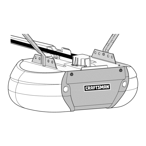
Owner's Manual/ManualDel Propietario
®
GARAGE DOOROPENER
ABRIDORDE PUERTADECOCHERA
ForResidentialUseOnly/S61opara usoresidencial
Model/Modelo 139.3043
I'll
Z
Read andfollow all safety rulesand operating
instructions beforefirst useof this product.
Fastenthe manualnear the garage doorafter
installation.
Periodic checksofthe openerare requiredto
ensuresafe operation.
DONOTenable the Timer-To-Closefeature if
you are installingthe garagedooropeneron
a one-piecedoor. The Timer-To-Closeis to be
usedONLYwithsectional doors.
Leery seguirtodaslas reglas de seguridady
las instrucciones de operaci6nantes de usar
esteproducto por primera vez.
Guardareste manualcerca de la puerta de la
cochera.
Se debenrealizar revisionesperi6dicas del
abridor de puertas para asegurarsu operaci6n
segura.
NOusoel caracteristicaTemporizadorpara
cierrase el abridorde la puerta es instalado
en un puertade unsola pieza. El caracteristica
temporizadorpara cierra es SOLOparauso con
puertasseccionales.
I'll
"O
;z=,
Z_
Sears Brands Management Corporation, Hoffman Estates, IL 60179 U.S.A
www.craftsman.com
Advertisement
Chapters
Table of Contents
Troubleshooting

Related Manuals for Craftsman 139.3043


Summary of Contents for Craftsman 139.3043
- Page 1 The Timer-To-Closeis to be NOusoel caracteristicaTemporizadorpara usedONLYwithsectional doors. cierrase el abridorde la puerta es instalado en un puertade unsola pieza. El caracteristica temporizadorpara cierra es SOLOparauso con puertasseccionales. Sears Brands Management Corporation, Hoffman Estates, IL 60179 U.S.A www.craftsman.com...
-
Page 2: Table Of Contents
TABLE OF CONTENTS Adjustment 27-29 Introduction Introduction ........Safety symbol review and signal word review ....Program the travel ........Preparing your garage door ......Test the safety reversal system......Tools needed ........Test The Protector System® ......Planning ........... Carton inventory ........ -
Page 3: Preparingyour Garage Door
Preparingyour garage door Before you begin: To prevent possible SERIOUSINJURYor DEATH: • Disable locks. • ALWAYScall a trained door systems technician if garage • Removeany ropes connected to garage door. door binds, sticks, or is out of balance. An unbalanced •... -
Page 4: Planning
Planning Identify the type and height of your garage door. Survey your Doyou have an access door in addition to the garage door? If garage area to see if any of the conditions below apply to your not, Model 139.53702 Emergency Key Releaseis required. See installation. -
Page 5: Planning
Planning(Continued) ONE-PIECE DOOR INSTALLATIONS Without a properly working safety reversal system, persons • Generally, a one-piece door does not require reinforcement. If (particularly small children) could be SERIOUSLYINJUREDor your door is lightweight, refer to the information relating to KILLEDby a closing garage door. sectional doors in Installation Step 8. -
Page 6: Cartoninventory
CartonInventory Your garage door opener is packaged in one carton which Parts may be stuck in the foam. Hardware for assembly and contains the motor unit and all parts illustrated below. installation is shown on the next page. Savethe carton and Accessories will depend on the model purchased. -
Page 7: Hardwareinventory
HardwareInventory Separateall hardware and group as shown below for the assembly and installation procedures. ASSEMBLYHARDWARE !!!!!!!!!1) Q Bolt 1/4"-20xl-3/4" (2) Lock Nut Lock Washer 1/4"-20 (2) 3/8" (1) 3/8" (1) Spring/Trolley Nut (1) Spring Nut Label Master Link (2) Idler Bolt (1) Trolley Threaded Shaft (1) INSTALLATION HARDWARE Handle... -
Page 8: Assemble The Rail And Install The Trolley
ASSEMBLY STEP Assemble the Rail and Install the Trolley To prevent INJURY from pinching, keep hands and fingers To avoid installation difficulties, do not run the garage door away from the joints while assembling the rail. opener until instructedto do so. The front rail has a cut out "window"... -
Page 9: Install The Idler Pulley
ASSEMBLY STEP Install the Idler Pulley 1. Laythe belt beside the rail, as shown. Graspthe end with the hooked trolley connector and pass approximately 12" (30 cm) of belt through the window. Keepthe ribbed side toward the rail, and allow it to hang until Assembly Step 5. 2. -
Page 10: Install The Belt
ASSEMBLY STEP Install the Belt To avoid possible SERIOUSINJURYto fingers from moving 1. Pull the belt around the idler pulley and toward the trolley. garage door opener: The ribbed side must contact the pufley. • ALWAYS keep hand clear of sprocket while operating opener. 2. -
Page 11: Set The Tensionand Install The Sprocketcover
ASSEMBLY STEP Set the Tensionand Install the SprocketCover 1. By hand, thread the spring trolley nut on the threaded shaft until it is finger tight against the trolley. Do not use any tools. 2. Removethe screwdriver. 3. Insert a flathead screwdriver tip into one of the nut ring slots and brace it firmly against the trolley. -
Page 12: Determine The Headerbracketlocation
INSTALLATION STEP Determine the HeaderBracketLocation Un.f!nished To prevent possible SERIOUSINJURYor DEATH: Ceiling _ BRACKETMOUNTCEILINGOPTIO • Headerbracket MUST be RIGIDLY fastened to structural Header Wall support on header wall or ceiling, otherwise garage door Vertical Centerline might NOT reverse when required. DONOT install header of Garage Door bracket over drywall. -
Page 13: Install The Header Bracket
INSTALLATION STEP Install the Header Bracket Wall Mount You can attach the header bracket either to the wall above the garage door, or to the ceiling. Follow the instructions which will work best for your particular requirements. Do not install the header bracket over drywall. -
Page 14: Attach The Rail To The Header Bracket
INSTALLATION STEP Attach the Raft to the Header Bracket 1. Position the opener on the garage floor below the header bracket. Use packing material as a protective base. NOTE:If the door spring is in the way, you will need help. Have someone hold the opener securely on a temporary support to allow the rail to clear the spring. -
Page 15: Positionthe Opener
INSTALLATION STEP Positionthe Opener To prevent damage to garage door, rest garage door opener rail Follow instructions which apply to your door type as illustrated. on 2x4 placed on top section of door. SECTIONAL DOOROR ONE-PIECE DOORWITH TRACK A 2x4 laid flat is convenient for setting an ideal door-to-rail distance. -
Page 16: Hang The Opener
INSTALLATION STEP Hang the Opener To avoid possible SERIOUSINJURYfrom a falling garage door Three representative installations are shown. Yours may be opener, fasten it SECURELY to structural supports of the different. Hanging brackets should be angled (Figure 1) to provide garage. -
Page 17: Install The Lights
INSTALLATION STEP Install the Lights To prevent possible OVERHEATING of the end panel or light 1. Press the releasetabs on both sides of lens. Gently rotate lens socket: back and downward until the lens hinge is in the fully open •... -
Page 18: Fastenthe Door Bracket
INSTALLATION STEP Fasten the Door Bracket Fiberglass, aluminum or lightweight steel garage doors WILL Follow instructions which apply to your door type as illustrated REQUIREreinforcement BEFORE installation of door bracket. below or on the following page. Contact your door manufacturer for reinforcement kit. A horizontal reinforcementbrace shouldbe long enoughto be securedto two or three vertical supports,A vertical reinforcementbrace shouldcover the height of the top panel,... -
Page 19: Fastenthe Door Bracket
Fasten the Door Bracket (Continued) ONE-PIECE DOORS Please read and comply with the warnings and reinforcement instructions on the previous page. They apply to one-piece doors also. • Center the door bracket on the top of the door, in line with the header bracket as shown. -
Page 20: Connect Door Arm To Trolley
INSTALLATION STEP Pulley Connect Door Arm to Trolley cm) min. __.),, Follow instructions which apply to your door type as illustrated Figure 1 below and on the following page. SECTIONAL DOORSONLY Outer Trolley Make sure garage door is fully closed. Pull the emergency release Clevis Pin handle to disconnect the outer trolley from the inner trolley. -
Page 21: Attach The Warning Labels
ConnectDoorArm to Tro//ey(Continued) ALL0NE-PIECEDOORS IMPORTANT." Thegroove on the straight door arm MUST face away from the curved door arm (Figure 5). Figure5 INCORRECT CORRECT 1. Close the door. Disconnect the trolley by pulling the emergency releasehandle. 2. Fastenthe straight door arm and the curved door arm together to the longest possible length (with a 2 or 3 hole overlap). -
Page 22: Install The Door Control
STEP Install the Door Control To prevent possible SERIOUSINJURYor DEATHfrom INTRODUCTION electrocution: NOTE:Older Craftsman accessories and third party products are • Be sure power is NOT connected BEFORE installing door control. not compatible. • Connect ONLYto 12 VOLTlow voltage wires. -
Page 23: Install The Door Control
Install the Door Control (Continued) WIRETHE DOORCONTROL TO THE GARAGEDOOROPENER Figure4 DoorControlConnections (FIGURE4) Pre-wired installations:When wiring the door control to the garage door opener make sure you use the same wires that are connected to the door control. 1. Run the white and red/white wire from the door control to the garage door opener. - Page 24 Instal/The ProtectorSystem ® (Continued) Figure I DOORTRACK MOUNT (RIGHT SIDE) INSTALLING THE BRACKETS Be sure power to the opener is disconnected.Install and align iDoor the brackets so the sensors will face each other across the garage \ Track door, with the beam no higher than 6" (15 cm) above the floor. They may be installed in one of three ways, as follows.
- Page 25 Insta// TheProtectorSystem ® (Continued) MOUNTINGANDWIRING THE SAFETYREVERSING SENSORS Figure 5 Mounting: • Slide a 1/4"-20xl/2" carriage bolt head into the slot on each sensor. Use wing nuts to fasten sensors to brackets, with Carriage Bolt lenses pointing toward each other across the door. Be sure the lens is not obstructed by a bracket extension (Figure 5).
-
Page 26: Electrical Requirements
INSTALLATION STEP Electrical Requirements To prevent possible SERIOUSINJURYor DEATHfrom To avoid installationdifficulties, do not run the opener at this electrocution or fire: time. • Be sure power is NOT connected to the opener, and To reduce the risk of electric shock, your garage door opener has disconnect power to circuit BEFORE removing cover to a grounding type plug with a third grounding pin. -
Page 27: Aligning The Safety Reversing Sensors
Aligning the Safety Reversing Sensors (Continued) IF THE AMBERLED ONTHE SENDINGSENSORIS NOT IF THE GREENLED ON THE RECEIVINGSENSORIS NOT GLOWING: GLOWING: 1. Make sure the sensor wire is not shorted/broken. 1. Make sure there is power to the garage door opener. 2. -
Page 28: Programthe Travel
ADJUSTMENT STEP Programthe Travel Without a properly installed safety reversal system, persons (particularly small children) could be SERIOUSLYINJUREDor 1. Press and hold the KILLED by a closing garage door. Adjustment Button until the • Incorrect adjustment of garage door travel limits will interfere UP Button begins to flash with proper operation of safety reversal system. -
Page 29: Adjustment
ADJUSTMENT STEP Testthe SafetyReversal System Without a properly installed safety reversal system, persons TEST (particularly small children) could be SERIOUSLYINJUREDor • With the door fully open, place a 1-1/2" (3.8 cm) board (or a KILLEDby a closing garage door. 2x4 laid flat) on the floor, centered under the garage door. •... -
Page 30: Battery Backup
BATTERY BACKUP install the Battery To reduce the risk of FIREor INJURYto persons: 1. Unplug the garage door opener. • DisconnectALL electric and battery power BEFORE 2. Open the light lens on the right side panel of the garage door performing ANY service or maintenance. -
Page 31: Operation
OPERATION IMPORTANT SAFETYINSTRUCTIONS To reducethe risk of SEVERE INJURYor DEATH: 1. READAND FOLLOWALL WARNINGSAND INSTRUCTIONS. 10. Safety reversal system MUST be tested every month. Garage door MUST reverse on contact with 1-1/2" high 2. ALWAYS keep remote controls out of reach of children. (3.8 cm) object (or a 2x4 laid flat) on the floor. -
Page 32: Features
Features(Continued) USING YOURGARAGEDOOROPENER The garage door opener can be activated through a wall-mounted interrupts the sensor beam the garage door opener lights will door control, remote control, wireless keyless entry or blink 10 times. However, you can close the door if you hold the AssureLink accessory. -
Page 33: Smart Control Panel Setup
Smart ControlPane/Setup MENU NAVIGATION The features on the door control can be programmed through a series of menus on the screen and the navigation buttons. Refer to the descriptions below. Settings Screen Press the navigation button below the down arrow till you see The main screen displays the time, temperature, and current battery charge (if applicable). -
Page 34: Programming
Programming Your garage door opener has been programmed at the factory to operate with your remote control. The remote control can be programmed using the door control or the garage door opener. To program additional remote controls refer to the instructions provided with the additional remote controls. -
Page 35: To Openthe Door Manually
To Openthe Door Manually DISCONNECT THE TROLLEY Trolley To prevent possible SERIOUSINJURYor DEATHfrom a falling The door should be fully closed if garage door: possible. Pull down on the • If possible, use emergency releasehandle to disengage emergency releasehandle (so that trolley ONLYwhen garage door is CLOSED.Weak or broken the trolley releasearm snaps into a springs or unbalanceddoor could result in an open door... -
Page 36: Troubleshooting
TROUBLESHOOTING DIAGNOSTIC CHART Your garage door opener is programmed with self-diagnostic capabilities. The UP and DOWNarrows on the garage door opener flash the diagnostic codes. DIAGNOSTIC UP DOWN SYMPTOM CAUSE RESOLUTION CODE ARROW ARROW 1 FLASH 1 FLASH The garage door Safety sensors are Inspect sensor wires for a disconnected or opener will not... -
Page 37: Troubleshooting
DIAGNOSTIC CHART Your garage door opener is programmed with self-diagnostic capabilities. The UP and DOWNarrows on the garage door opener flash the diagnostic codes. DIAGNOSTIC UP DOWN SYMPTOM CAUSE RESOLUTION CODE ARROW ARROW 3 FLASHES 3 FLASHES The garage door Battery LEDflashing Replacethe logic board. -
Page 38: Repair Parts
REPAIR PARTS Rail Assembly Parts 41B4103-1 Spring trolley nut 144C54 Idler pulley 41A5250 Full belt assembly 12D598-1 "U" bracket NOT SHOWN 183A163 Wear pads Installation Parts PART DESCRIPTION 41A7563 Smart Control PaneP 41A7633 3-Button remote control 10A20 3V2032 Lithium battery 29B137 Visor clip 41A6147-10... -
Page 39: Motor Unit Assembly Parts
Motor Unit Assembly Parts PART PART DESCRIPTION DESCRIPTION 41C589-2 41A7635 Transformer and harness Sprocket with sprocket cover 41B135 Line cord 41D503-4 Cover 41B7418 Wire harness kit 108D77 Light lens 41D1624-1 Motor with travel module 41C279 Light socket 45DCT Receiver logic assembly 41A7611 Filter Board 41A7630... -
Page 40: Accessories
WARRANTY RESTRICTION This Craftsman Garage Door Opener Limited Warranty does not cover light bulbs, which are expendable parts, or repair parts necessary because of operator abuse or negligence, including the failure to install, adjust and operate this garage door opener according to instructions contained in the owner's manual. This limited warranty also does not cover any problems caused by interference. -
Page 41: Notes
NOTES... -
Page 42: Notes
NOTES... - Page 43 CONTENIDO Introducci6n Ajustes 27-29 Introducci6n ..........Revisi6n de los simbolos y t_rminos de seguridad ....Preparaci6n de la puerta de su cochera ......Programaci6n del desplazamiento ......Herramientas necesarias........Pruebe el sistema de seguridad de reversa ...... Planificaci6n ..........Prueba la Protector System _ ......... Inventario de la caja de cart6n .........
-
Page 44: Preparaci6Nde La Puerta De Su Cochera
Preparaci6nde la puerta de su cochera Antes de comenzar: Para evitar una LESIONGRAVEo INCLUSOLA MUERTE: • Quite los seguros. • SIEMPRE Ilame a un t_cnico profesional para que le d_ servicio a su • Retire cualquier cuerda o cable que est_ conectado a la puerta. puerta de cochera si _sta se atora, se pandeao est,. -
Page 45: Planificaci6N
Planificaci6n Identifique la altura y el tipo de su puerta de cochera. Reviseel _.reade 6Hay otra puerta que d_ acceso a la cochera? Si no es asi, ser_. su cochera y observe si alguna de las siguientes instalaciones necesario contar con el sistema de Ilave de emergencia Modelo corresponden a la suya. - Page 46 Planificaci6n (continUa) INSTALACION CON PUERTASDE UNASOLAPIEZA Sin un sistema de retroceso de seguridad que funcione debidamente, • Generalmente una puerta de una sola pieza no requiere refuerzos al cerrar la puerta de la cochera se corre el riesgo de que las personas adicionales.
-
Page 47: Inventario De La Caja De Cart6N
Inventario de la caia de cartdn Su abridor viene empacado en una caja de cart6n que contiene el motor y Toda la tornilleria y las piezas necesarias para el montaje e instalaci6n de las piezas que se muestran en la siguiente ilustraci6n. Tome nota de que su puerta se ilustran en la siguiente p@ina. -
Page 48: Inventario De Piezas
Inventario de piezas Antes de la instalaci6n, organice todas las piezas en grupos como se muestra en la siguiente ilustraci6n. TORNILLERIA Y PIEZAS PARA ELMONTAJE Pernode 1/4-20xl-3/4 de pulg. (2) Tuerca de Arandela de Tuerca de 1/4 de pulg.-20 (2) 3/8 de pulg. - Page 49 MONTAJE, PASO Monte e/fie/e insta/e e/tro/e Para evitar QUESE PELLIZQUE,conserve los manos y dedos lejos de No encienda ni use el abridor hasta que Ilegue al paso de la las juntas cuando monte el reil. instalaci6n correspondiente,de otra manera corre el riesgo de complicar el proceso de instalaci6n.
- Page 50 MONTAJE, PASO /nstale la po/ea Ioca 1. Ponga la cadena y cable a un lado del riel como se muestra en la ilustraci6n. Tome el extremo del cable y pase por la ventana aproximadamente 30 cm (12 pulg.) D_jelo que cuelgue hasta que Ileque al Paso 5 de Montaje.
- Page 51 MONTAJE, PASO /nsta/e /a banda Para evitar posibles LESIONESGRAVESen los dedos causadas por las 1. Jale la banda alrededor de la polea Ioca hacia el trole. El/ado partes m6viles del abridor de puerta de cochera: acanaiado debe estar en contacto con ia polea. •...
- Page 52 MONTAJE, PASO Fije la tensi6nde la banday instalaci6n de cubierta de/ portacadea 1. Enroscar y ajustar a mano la tuerca de presi6n del carro en el eje roscado. No usar herramientas. 2. Quitar el destornillador. 3. Introducir la punta de un destornillador en una de las ranuras de la tuerca y apoyarlo firmemente contra el carro.
- Page 53 INSTALACION, PASO Determine d6nde va a insta/ar la m_nsulade/cabeza/ Ciel°_acSa_ai_l Para evitar una posible LESIONGRAVEo INOLUSOLA MUERTE: • La m_nsula del cabezal DEBEquedar RJGIDAMENTE sujeta al Pared delantera soporte estructural en la pared delantera o en el cielo raso, de no ser asi es posible que la puerta de la cochera no retroceda cuando se Linea central vertical de la puerta de garaje...
- Page 54 INSTALACION, PASO Insta/e /a m_nsu/a de/cabeza/ Montaje en la pared La m_nsula del cabezal se puede fijar a la pared justo per encima de la puerta de la cochera o en el cielo raso. Siga las instrucciones que sean m_.sadecuadas para su cochera. No instale la m_nsula del cabezal en un inure false.
-
Page 55: Montaje
INSTALACION, PASO Co/oquee/fie/en la m_nsula de/cabeza/ 1. Coloque el abridor sobre el piso de la cochera debajo de la m_nsula del cabezal. Use el material de empaque como base para protegerlo. NOTA: Si el resorte de la puerta est# obstruyendo, va a necesitar ayuda. -
Page 56: Coloque El Abridor En Posici6N
INSTALACION, PASO Coloque el abridor en posici6n Para evitar que la puerta de cochera sufra da_os, apoye el riel del Siga las instrucciones correspondientes al tipo de puerta de su cochera, abridor de la misma sobre un pedazode madera de 5x10 cm como se muestra en la ilustraci6n. -
Page 57: Cuelgueel Abridor
INSTALACION, PASO Cuelgueel abridor Para evitar la posibilidad de una LESIONGRAVEsi se cae el abridor de Aqui se muestran tres ejemplos distintos para la instalaci6n; sin la puerta de cochera, suj_telo FIRMEMENTEa los soportes embargo, es posible que su cochera no concuerde con ninguno de ellos. estructurales de la cochera. -
Page 58: Instale Las Luces
INSTALACION, PASO Instale /as luces Para evitar un posible SOBRECALENTAMIENTO del portabombillas: 1. Oprima las leng_Jetas de liberaci6n a ambos lados de la lente. Rote la • Usar ONICAMENTEI_.mparasincandescentesA19 o fluorescentes lente suavemente hacia atr_.sy hacia abajo hasta que la bisagra quede compactas. -
Page 59: Fije La M_Nsula De La Puerta
INSTALACION, PASO 8 Fije la m6nsula de la puerta En puertas de garaje de fibra de vidrio, aluminio o acero liviano ES Siga las instrucciones que correspondan al tipo de puerta que usted NECESARIOcolocar los refuerzos ANTESde instalar la m_nsula de la tenga, seg_n las ilustraciones siguientes o de la pr6xima p_.gina. - Page 60 Fije /a m_nsu/a de la puerta (contin#a) PUERTASDE UNASOLAPIEZA Lea y respetetodas las advertencias e instrucciones respecto a los refuerzos contenidas en la p_.ginaanterior, ya que son v_.lidastambi_n para puertas de una sola pieza. • Centre la m_nsula en la parte superior de la puerta, alineadacon la m_nsula del cabezal, tal se muestra en la ilustraci6n.
-
Page 61: Conecteel Brazo De La Puerta Al Trole
INSTALACION, PASO Polea Conecteel brazo de la puerta al trole Lo menos Siga las instrucciones que correspondan al tipo de puerta de cochera que Figura 1 usted tenga, como se muestra a continuaci6n yen la p_.ginasiguiente. SI3LOPARA PUERTASSECCIONALES Cerci6rese de que la puerta de la cochera est6 completamente cerrada. exterior Tire de la manija de emergencia para desconectar el trole exterior del trole interior. -
Page 62: Colocar Las Etiquetas De Advertencia
Conectee/brazo de/a puerta a/tro/e (contin#a) TODASLAS PUERTASDE UNASOLAPIEZA IMPORTANTE:El ranura ei7el brazo recto de la puerta DEBEvolt#ese del brazo curvado de la puerta (Figura 5). Figura 5 CORRECT0 INCORRECT0 1. Cerrar la puerta. Desconectar el carro tirando de la manija de emergencia. - Page 63 INTRODUCCION MUERTEpor electrocuci6n: • DesconecteTODA la corriente el_ctrica y de la bateria ANTESde NOTA:Antiguos accesorios Craftsman o de terceras marcas no son realizar cualquier servicio o mantenimiento. compatibles. • Conecte el control SOLOa cables de bajo voltaje de 12 VOLTIOS.
-
Page 64: Instale La Protectorsystem
Instalar e/contro/de/a puerta (continUa) TENDERLOSCABLESDESDEELCONTROLHASTAELABRE-PUERTA Figura4 (FIGURA4) Conexiones del control de la puerta Instalaci6n con cableadoexistente:Asegurarse de usar los mismos cables que ya est&nconectados al control de la puerta. 1. Instalar los conductores blanco y rojo entre el control y el abre-puerta. Fijar el cable a la pared y al techo con broches (a menos que se utilicen cajas de conexi6n o sea una instalaci6n existente). - Page 65 Instale la ProtectorSystem ® (contin#a) INSTALACION DE LAS MI_NSULAS Figura 1 INSTALACI6N EN ELCARRiL DE LA PUERTA(LADO DERECHO) Asegdrese de queel abridor no est_ conectadoa la corriente el_ctrica. Instale y alinee las m_nsulas de manera que los sensores Carril de est_n uno frente al otro en los lados opuestos de la puerta, a una III .
- Page 66 Insta/e /a ProtectorSystem ® (contin#a) MONTAJEY CABLEADO DE LOSSENSORESDESSISTEMADE Figura5 SEGURIDADDE REVERSA Montaje: • Introduzca la cabeza de un perno de coche de 1/4 de pulg.-20xl/2 de pulg. en la ranura correspondiente de cada sensor. Ajuste los sensores alas m_nsulas con tuercas mariposa, con los lentes enfrentados, uno de cada lado de la puerta.
-
Page 67: Alineaci6N De Los Sensores De Reversa De Seguridad
INSTALACION, PASO 13 Requisitos p ara /a insta/aciCn e / ctrica Para evitar la posibilidad de una LESIONGRAVEo INCLUSOLA Para evitar dificultadescon la instalaciCn, no encienda ni use el MUERTEpor electrocuci6n o incendio: abridor en este momento. • Cerci6rese de que el abridor NO est_ conectado a la energia el_ctrica, y desconecte la alimentaci6n el_ctrica al circuito ANTESde Para reducir el riesgo de choque el_ctrico, su abridor para puerta de quitar la cubierta para establecer la conexi6n del cableado... -
Page 68: Ajustes Introducci6N
A/ineaci6n de/os sensores de reversa de seguridad (continUa) SI ELLEDAMBAR DEL SENSOREMISORNO SE ENCENDIERA: SI ELLED VERDEDEL SENSORRECEPTORNO SE ENCENDIERA: 1. Verificar que Ilegue energia ebctrica al abre-puerta. 1. Verificar que no haya un cortocircuito ni el sensor est_ roto. 2. -
Page 69: Programaci6N Del Desplazamiento
AJUSTES, PASO Programaci6nde/desp/azamiento Si el sistema de retroceso de seguridad no se ha instalado debidamente, las personas (y los ni_os peque_os en particular) podrian sufrir LESIONESGRAVESo INCLUSOLA MUERTEcuando se 1. Mantener pulsado el botdn de cierra la puerta de la cochera. regulacidn hasta que el botdn de subida se encienda •... -
Page 70: Pruebe El Sistema De Seguridad De Reversa
AJUSTES, PASO Pruebe e/sistema de seguridadde reversa Si el sistema de reversa de seguridad no se ha instalado debidamente, PRUEBA las personas (y los niSos pequeSos en particular) podrian sufrir LESIONESGRAVESo INCLUSOLA MUERTEcuando se cierre la puerta • Abra completamente la puerta, coloque un pedazode madera de del garaje. -
Page 71: Bateria De Reversa
2. Abrir la tapa de la luz del lado derecho de la unidad. Con un realizar cualquier servicio o mantenimiento. destornillador Phillips quitar la tapa de bateria del abre-puerta. • Use SOLAMENTEla pieza Craftsman N° 41B822 como bateria de repuesto. 3. Colocar parcialmente la bateria en su compartimiento, con los terminales hacia afuera. -
Page 72: Operaci6N
OPERACION INSTRUCCIONES I MPORTANTES DESEGURIDAD Para reducirel riesgo de LESIONES GRAVES o LA IViUERTE: 1. LEA Y SIGA TODASLAS ADVERTENCIAS Y LAS INSTRUCCIONES DE 10. El sistema de reversa de seguridad se DEBEprobar cada mes. La OPERACION. puerta DEBEinvertir su direcci6n al entrar en contacto con un objeto de 3.8 cm (1-1/2 de pulg.) de altura (o un tabl6n de madera 2. -
Page 73: Funciones
Funciones (contin#a) USO DELABRE-PUERTA DE GARAJE El abre-puerta puede activarse con un control fijo, con un control remoto, intermitentemente diez veces. La puerta podr_,cerrarse con el bot6n del con una cerradura digital a teclado o con un accesorio AssureLink control fijo o la cerradura digital a teclado. Los sensores de inversi6n no afectan la apertura de la puerta. -
Page 74: Configuraci6N De La Smart Control Panel
Configuraci6n de/a Smart Contro/Pane/ NAVEGACII_N DE MENUS Las funciones del control pueden programarse a trav_s de los men_s y botones de navegaci6n. V_anse las siguientes descripciones. Panta//a Calibraciones En la pantalla principal se muestra la hora y temperatura, y si se usa una Para ver el men_ de Par_.metros,pulsar el bot6n bajo la flecha descendente hasta ver TEMPERATURA. -
Page 75: Programaci6N
ProgramaciCn Su abre-puertas de garaje ya viene programado de f_.brica para operar con su control remoto. El control remoto puede programarse con el control fijo o con el mismo abre-puerta. Para programar otros controles remotos consultar las instrucciones que vengan con ellos. C()MO AGREGARUN CONTROLREMOTOUSAREL C()MO AGREGAR,REPROGRAMAR 0 CAMBIARCONTROLREMOTO/UN BOTONLEARN(APRENDER) -
Page 76: C6Moabrir La Puerta Manualmente
C6moabrir la puerta manualmente Trole COMO DESCONECTAR ELTROLE: Para evitar la posibilidad de una LESIONGRAVEo INCLUSO La puerta debe estar completamente LA MUERTEsi la puerta de la cochera se cae: cerrada si es posible. Tire de la manija • De ser posible, use la manija de liberaci6n de emergencia para soltar de liberaci6n de emergencia (de el trole SOLOcuando la puerta de la cochera est_ CERRADA.Si los manera que el brazo de liberaci6n del... -
Page 77: Diagn6Sticode Problemas
DIAGNOSTICO DE PROBLEMAS TABLADE DIAGNI_STICO Su abre-puertas de garaje viene programado con funciones de autodiagn6stico. Las flechas hacia ARRIBA y ABAJO se encienden para mostrar los c6digos de diagn6stico. CODIGODE FLECHAHACIA FLECHAHACIA SINTOMA CAUSA SOLUCION DIAGNOSTICO ARRIBA ABAJO 1 DESTELLO 1 DESTELLO El abre-puerta no cierra Sensores de... - Page 78 TABLADE DIAGNOSTICO Su abre-puertas de garaje viene programado con funciones de autodiagn6stico. Las flechas hacia ARRIBA y ABAJO se encienden para mostrar los c6digos de diagn6stico. CODIGODE FLECHAHACIA FLECHAHACIA SINTOMA CAUSA SOLUCION DIAGNOSTICO ARRIBA ABAJO 3 DESTELLOS 3 DESTELLOS El abre-puerta est,. LED verde destella, Cambiar la tarjeta de Idgica.
-
Page 79: Accesorios
LIMITACIONES DE LA GARANTJA Esta garantia limitada del abre-puerta de garaje Craftsman no abarca I_mparas porque son insumos consumibles, ni repuestos que sean necesarios por maltrato o negligencia por parte del usuario, y esto incluye ignorar las instrucciones del manual para la instalaci0n, regulaci0n y uso del abre-puerta de garaje. Esta garantia limitada tampoco cubre problemas causados por interferencia. - Page 80 Your Home For troubleshooting, product manuals and expert advice: www.managemylife.com For repair- in your home - of all major brand appliances, lawn and garden equipment, or heating and cooling systems, no matter who made it, no matter who sold it! For the replacement parts, accessories owner's manuals that you need to do-it-yourself.