Table of Contents
Advertisement
OWNER'S
MANUAL
MODEL NO,
917.255950
Caution:
Read and
Follow All Safety
Rules And
Instructions
Before
Operating This
Equipment
®
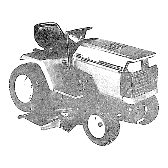
18.0 HP TWIN CYLmNDER
ELECTRIC START
44" MOWER
6 SPEED
GARDEN TRACTOR
. Assembly
o Operation
° Maintenance
• Service and Adjustment
, Repair Parts
3ea_s, Roebuck and Co., Chicago, IL 60684 U.S.A.
Advertisement
Table of Contents

Related Manuals for Craftsman 917.255950


Summary of Contents for Craftsman 917.255950
- Page 1 OWNER'S MANUAL MODEL NO, 917.255950 ® Caution: Read and 18.0 HP TWIN CYLmNDER Follow All Safety Rules And ELECTRIC START Instructions Before Operating This 44" MOWER Equipment 6 SPEED GARDEN TRACTOR . Assembly o Operation ° Maintenance • Service and Adjustment , Repair Parts 3ea_s, Roebuck and Co., Chicago, IL 60684 U.S.A.
-
Page 2: Carburetor
SAFETY RULES CAUTION: ALWAYS DISCONNECT SPARK PLUG WIRE AND PLACE WIRE WHERE ITCAN- NOT CONTACT SPARK PLUG TO PREVENT ACCIDENTAL STARTING WHEN SETTING UP, TRANSPORTING, ADJUSTING OR MAKING REPAIRS, IMPORTANT SAFETY STANDARDS REQUIRE OPERATOR PRESENCE CONTROLS TO MINIMIZE THE RISK OF INJURY, YOUR UNIT IS EQUIPPED... - Page 3 PRODUCT SPECIFICATIONS CONGRATULATIONS on your purchase of a Sears tractor. It has been designed, engineered and manufactured to give you the best possible dependablility and performance, HORSEPOWER: 18.0 IASOLINE CAPACITY: 3,5 GALLONS Should you experience any problem you cannot easily rem- edy.
-
Page 4: Table Of Contents
TABLE OF CONTENTS OPERATION ......11-14 SAFETY RULES ..... ,,l°,,i,,,°t,2 MAINTENANCE ....... 15-18 PRODUCT SPECIFICATIONS . , . o,,,°,°,_,,,°3 ... 19-25 CUSTOMER RESPONSIBILITIES SERVICE AND ADJUSTMENTS WARRANTY ....STORAGE ......omu==°°,_,=,,5 TROUBLESHOOTING ....27-28 TABLE OF CONTENTS .. - Page 5 ,,,, ACCESSO ES AND ATTACHMENTS These accessor es and attachments were available when the unit was purchased, They are also available at most Sears retail outlets, catalog and service centers. MOSL Sears stores can order these items for you when you provide the mode[ number of your tractor, ENGINE MAINTENANCE...
- Page 6 CONTENTS OF HARDWARE PACK illl Parts Bag contents shown full size Parts, packed separately in carton Seat Battery acid (1) Knob (1) Washer 17/32 x 1 3/16 x 12 Ga. Steering Wheel Battery (1) Shoulder Bolt 5/16 - 16 I', _---" "_ L Owner's Manual Parts Bag...
- Page 7 ASSEB BLY TOOLS REQUIRED FOR ASSE!_BLY STEERING A socket wrench set will make assembly easier. Standard WHEEL_z; INSERT wrench sizes are listed. (2) 7/16" wrenches (I) Tire Pressure Gauge . LOCKWASHER HEXBOLT STEER'NGWHEEL (1) Adjustable Wrench (1) Utility Knife When right or left hand is mentioned in this manual, it means when you are in the operating position (seated behind the FLAT W;-',SitER steering wheel).
- Page 8 ASSEMBLY HOW TO SET UP YOUR TRACTOR INSTALL SEAT (See FIG. 4) Adjust seat before tightening adjustment knob. PREPARE BATTERY (See FIG. 3) • Remove cardboard packing on seat pan. • Place seat on pan and assemble shoulder bolt, CAUTION: Wear eye and face shield.
- Page 9 ASSEMBLY INSTALL MOWER AND DRIVE BELT • First connect RED battery cable to positive (+) battery ter- minal with hex bolt, flat washer, Iockwasher and hex nut Your unit has been shipped with the front mower suspension as shown. Tighten securely. bracket banded to the frame.
-
Page 10: Clutch Pulley
ASSEMBLY CHECK DECK LEVELNESS GAUGE r_ -...-----' RETAINER WHEEL For best cutting results, mower housing should be properly leveled. See "TO LEVEL MOWER HOUSING" in the Serv- BAR_ ice and Adjustments section of this rnanual GAUGE CHECK FOR PROPER POSITION OF ALL BRACKET BELTS... - Page 11 OPERATION KNOW YOUR TRACTOR READ THIS OWNER'S MANUAL AND SAFETY RULES BEFORE OPERATING YOUR TRACTOR. C0rnpare the illustrations with your Tractor to familiarize yourself with the locations of various controls and adjustments Save this manual for future reference. THROTTLE CONTROL ATTACHMENT CLUTCH SWITCH...
- Page 12 OPERATION The operation of arty tractor can result In foreign objects thrown Into the eyes, which can result in severe eye damage. Always wear safety glasses or eye shields while operating your tractor or before performing any adjustments or repairs. We recommend wide vision safety mask for over the spectacles or standard safety glasses, available at Sears Retail or Catalog Stores.
- Page 13 OPERATION -,,,i TO OPERATE ON HILLS TO ADJUST GAUGE WHEELS (See FIG. • Adjust mower to desired cutting hetghtr CAUTION: DO not drive up or down hillsi-" • Lower mower with lift contrOlr Remove rear retainer spring with slopes greater than 15 and do not R and clevis pin which secure each gauge wheel, drive across any slope.
- Page 14 OPERAT[O MOWING TIPS GASOLINE • Tire chains cannot be used when the mower housing isat- • Fill fuel tank. Use fresh, clean, regular unleaded gasoline. tached to unit. (Use of leaded gasoline will increase carbon and lead ox- ide deposits and reduce valve life) •...
- Page 15 FILLIN DATES ,__'_._ _A£,_ A,,,__, REGULAR SERVICE _f_FSERVICE DATES lU,, Check Brake Operation aT CheckTire Pressure Check for Loose Fasteners Sharpen/Replace Mower Blades Lubricate Pivot Points Check Battery Level/Recharge Clean Battery and Termlnals Lubricate Tie Rod Ball Joints Check Engine Oil Level Change Engine Oil Clean Air Filter/Foam Pre-cleaner Clean Air Screen...
- Page 16 MAINTENANCE TRACTOR TO SHARPEN BLADE (See FIG. 19) Care should be taken to keep the blade balanced. An unbal- Always observe safety rules when performing any mainte* anced blade will cause excessive vibration and eventual nance damage to mower and engine, TIRES °...
- Page 17 NTENANCE Remove oil filler cap, Be careful not to allow dirt to enter BATTERY (See FIG. 21) the engine when changing oil. Your unit has a battery charging system which is sufficient for normal use. However, periodic charging of the battery ENGINE OIL with an automotive charger will extend its life.
- Page 18 MAINTENANCE CLEAN AIR SCREEN (See FIG. 25) Air screen must be kept free of dirt and chaff to prevent en- gine damage from overheating. Clean with a brush or com- pressed air to remove dirt, stubborn dried gum fibers. CLEAN ENGINE COOLING FINS...
- Page 19 i i, i i,i ADJUSTMENTS $EnvucE CAUTION: BEFORE PERFORMING ANY SERVICE OR ADJUSTMENTS: Depress clutch/brake pedal fully and set parking brake. Place gearshift lever In "NEUTRAL" position. Place attachment clutch In "DISENGAGED" position. Turn Ignition key "OFF" and remove key. Make sure the blades and all moving parts have completely stopped.
- Page 20 S:RVmCI5 AND .ADJUSTMENTS FRONT-TO-BACK ADJUSTMENT(See FIGS 31and 32) TO ADJUST MOWER DRIVE BELT (See FIG. 33) To obtain the best cutting results, the mower housing should be adjusted so the back is approximately 7/8" to 1-1/8" • Lower mower with attachment lift control. higher than the front when the mower is in its highest posi- °...
- Page 21 SERVICE AND ADJUSTMENTS TO REPLACE MOWER BLADE DRIVE BELT TO ADJUST BRAKE (See FIGS. 35 and (See FIG. Your unit is equipped with an adjustable brake system which is mounted on the left side of the transaxle Park the tractor on level surface. Engage parking brake. For assistance, there is a belt installation guide decal on the un- If unit requires more than six (6) feet stopping distance at derside of mower belt cover,...
- Page 22 CE AN ADJUSTMENTS TO REPLACE MOTION DRIVE BELT (See FLATIDLER CLUTCHPULLEY FIGS. 37 and 38) Parkthetractoronlevelsurface_ Engageparkingbrake. ease of service there is a t2eltinstallation guide decal on bot- tom side of left footresLI tt is not necessary to remove mower. BELT REMOVAL- •...
- Page 23 SERVICE AND ADJUSTMENTS TO START ENGINE WITH A WEAK BATTERY TO REPLACE FUSE (See FIG, 40) Replace with 30 amp automotive-type plug-in fuse fuse holder is located behind the dash. i i, CAUTION: Lead-acid batteries generate TO REPLACE HEADLIGHT BULB explosive gases.
- Page 24 ADJUSTMENTS SERVUCE AN TO REMOVE HOOD AND GRILL ASSEMBLY (See FIGS. 42 and 43) • Lift hood Disconnect headlight wiring connection_ • Unscrew one screw at rear of each side panel. SCREW FIG. 42 • Pivot hood and side panel forward and lift off tractor. * To replace, reverse above procedure.
-
Page 25: Throttle Control Cable
SERVUCE AND ADJUSTMENTS ENGINE High speed stop is factory adjusted Do not adjust - damage may resulL TO ADJUST THROTTLE CONTROL CABLE IMPORTANT: NEVER TAMPER WITH THE ENGINE (See Fig. 44 & 45) GOVERNOR, WHICH IS FACTORY SET The throttle control has been preset at the factory and FOR PROPER ENGINE SPEED. -
Page 26: Storage
S'TO RAGE Immediate!y prepare your tractor for storage at the end of ENGINE the season or if the unit will not be used for' 30 days or more. FUEL SYSTEM IMPORTANT: IT IS IMPORTANT TO PREVENT CAUTION: Never store the tractor wlthJ DEPOSITS FROM FORMING IN ESSEN- gasoline in the tank inside a building where_ TIAL FUEL SYSTEM PARTS SUCH AS... -
Page 27: Air Filter
TROUBLESHOOTUNG POUNTS CORRECTION PROBLEM CAUSE 1. Fill fueltank. 1, Out of fuel. Wilt not start 2. See TO START ENGINE in Operation section. . Engine not "CHOKED" properly. Wait several minutes before attempting to stad. Engine flooded. 4_ Bad spark plug. 4_ Replace spark plug. -
Page 28: Seat
=TF OUBLESHOO'T NG POINTS PROBLEM CAUSE CORRECTION Engine continues 1_ Check wiring, switches and connections, If not 1_ Faulty operator-safeLy presence control system. to run when oper- corrected, contact Sears Setvice Department. ator leaves seat with attachment clutch engaged Poorcut- uneven 1.