Table of Contents

Related Manuals for Craftsman 917.255930


Summary of Contents for Craftsman 917.255930
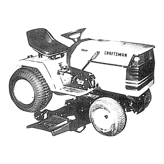
- Page 1 SEAl, S OWNER'S MANUAL MODEL NO. 917.255930 ® Caution: Read and follow all Safety Rules and lnstruchons Before Operating This Equipment , Assembly o Operation • Maintenance o Service and Adjustment • Repair Parts Sears, Roebuck and Co., Chicago, IL 60684 U.S.A.
- Page 2 SAFETY RULES REPAIRS. aNPORTANT SAFETY STANDARDS REQUIRE OPERATOR PRESENCE CONTROLS TO MINIMIZETHE RISKOF INJURY. YOUR UNIT IS EQUIPPED WITH SUCH CONTROLS° DO NOT ATTEMPT TO DEFEAT THE FUNCTION OFTHE OPERATOR PRESENCE CONTROLS UNDER ANY CIRCUMSTANCES. TRAINING: Know the controls and how to stop quickly, Read this owner's Never mow in wet or slippery grass, when traction is unsure, manual and instructions furnished with attachments.
-
Page 3: Customer Responsibilities
CONd_RATULATIONS on your purchase of a Sears PRODUCT SPECIFICATIONS Tractor, it has been designed, engineered and manu- factured to give you the best possible dependability and HORSEPOWER: 18 0 performance. Should you experience any problem you cannot easily GASOLINE CAPACITY: 3 5 GALLONS remedy, please... -
Page 4: Table Of Contents
,,,,,,,,,,,,, IIHI II II U,llll I,,, ....OF CONTENTS TABLE ........... ill, ..OPERATION ............11-14 SAFETY RULES ............MAINTENANCE ............. 15-18 PRODUCT SPECIFICATIONS ........CUSTOMER RESPONSIBILITIES ......... 3 SERVICE AND ADJUSTMENT .,.,' ......t 9-25 WARRANTY ..............STO RAG E .............. - Page 5 ACCESSORIES ATTACHMENTS These accessories and attachments were available when the unit was purchased, They are also available at most Sears retail outlets, catalog and service centers Most Sears stores can order these items for you when you provide the model number of your tractor, ENGINE MAINTENANCE SPARK PLUG...
- Page 6 ......... rllll, ......... CONTSNT$ OF HARDWARE PACK ......ii,,,u, i,,,,,,1,, 1,1,111,,,, nu,,,,,,,, n,,u n n,,i..Parts Bag contents shown full size Parts packed separately in carton =,,m ..... ,,,,,, ,,nu,n, = ..= Hn,n,= m,,, H,,, ,,, ..Seat Battery acid (1) Shoulder Bolt 5/16-18 Steering Wheel Battery...
- Page 7 ASSEMBLY ....:':Jl_,,,rui.u,L,_ ........TOOLS REQUIRED FOR ASSEMBLY STEERING A socket wrench set will make assembly easier. Standard WHEEL wrench sizes are listed INSERT (1) 9/16" wrench (1) Tire pressure gauge (2) 7/16" wrenches (1) Utility knife HEX BOLT (1) Adjustable wrench LOCK When right and left hand is mentioned in this manual, it...
- Page 8 ASSEMBLY ....i i i HOW TO SET UP YOUR TRACTOR INSTALL SEAT (See Fig. 4) Adjust seat before tightening adjustment knob= PREPARE BATTERY (See Fig. 3) • Remove cardboard packing on seat pan, • Place seat on pan and assemble shoulder knob. CAUTION: Wear eye and face shield°...
- Page 9 ASSEMBLY ,......111,1, 11.1 = ..INSTALL MOWER AND DRIVE BELT GAUGE Your unit has been shipped with the front mower suspen- WHEEL sion braket banded to the frame Remove bands and pivot bracket downward. MOWER INSTALLATION (See Figs. 5, 6, 7 and 8) GAUGE __,,,_ •...
- Page 10 CHECK FOR PROPER POSITION OF ALL BELTS See the figures that are shown for replacing motion, mower drive, and mower blade drive belts in the Service and Adjustments section of this manual. Verify that the belts are routed correctly ACCESS INSTALL BATTERY (See Figs.
- Page 11 ......== ,= OPERATION KNOW YOUR LAWN RIDER READ THIS OWNER'S MANUALAND SAFETY RULES BEFORE OPERATING YOUR LAWN RIDER. Compare the illustrations with your Tractor to familiarize yourself with the location of various controls and adjustments, Save this manua! for future reference THROTTLECONTROL ATTACHMENT CLUTCH...
- Page 12 ,,ui i,i1, i1,,,,, ,,t OPERATmON H,,, li,,!,u, li, ,, Nil,, , i, L,,,,m, ,, N,,, The operation of any tractor can result in foreign objects thrown into the eyes, which can result in severe eye damage° Always wear safety glasses or eye shields before starting your tractor and while moving, We recommend Wide Vision Safety Mask for over the spectacles or standard safety glasses.
- Page 13 ,I,,H = ......OPERATmON TO OPERATE ON HILLS TO ADJUST GAUGE WHEELS (See Fig. 14 ) =ll=lHH=, • Adjust mower to desired cutting height, CAUTION; Do not drive up or down Lower mower with lift control. Remove rear retainer hills with slopes greater than 15 0 and spring and clevis pin which secure each gauge wheel do n,,o,!,,,d,rive ac,,r,o,ss any slope.
-
Page 14: Carburetor
MOWING TiPS ADD GASOLINE • Tire chains cannot be used when the mower housing • Fill fuei tank Use fresh, clean, regutar unleaded is attached to unit. gasoline. (Useof leaded gasolinewitl increasecarbon and lead oxide deposits and reduce valve life), •... - Page 15 MAINTENANCE SCHEDULE 7___o_/" /_/_-_._.O_ FILLINDATES AS YOU COMPLETE ._'_.,_.#_._ _O?'_ REGU_R SERV!CE .,_'__._:/£,_"SERVICE DATES Check Brake Operation _,Gf Check Tire Pressure Check for Loose Fasteners 6/#4 Sharpen/Replace Mower Blades Lubrication Chart . 6/ ,Check BatterY Level/Recharge ..Clean Battery and Terminals 6# 4 Check Transmission Cooling Adjust Blade Belt(s) Tension...
- Page 16 ii== ,, =,=, i H= NTENANCF= , 11, ====,,,=l ==Ni= _--_--m TO SHARPEN BLADE (See Fig. 19) TRACTOR Care should be taken to keep the blade balanced Always observe safety rules when performing any mainte- unbalanced blade will cause excessive vibration and even- nance, tual damage to mower and engine.
- Page 17 TO CHANGE ENGINE OIL (See Figs. 22, 23 and 24) BATTERY (See Fig. 21) Determine temperature range expected before oil change° Your unit has a battery charging system which is sufficient All oil must meet API service classification SG, for normal use. However, periodic charging of the battery with an automotive charger will extend it's life, •...
- Page 18 ,, u,,uHu NTENANCE SCREEN (See Fig. 25) CLEAN COVER Air screen must be kept free of dirt and chaff to prevent engine damage from overheating, Clean with a wire brush KNOB WASHER or compressed air to remove dirt and stubborn dried gum CARTRIDGE PLATE fibers.
- Page 19 SERVICE AND ADJUSTMENTS ,I,I,HI ,,1,11,,,11, ,H,I, CAUTION: BEFORE PERFORMING ANY SERVICE OR ADJUSTMENTS: • Depress clutch/brake pedal fully and set parking brake. • Place gearshift lever In "NEUTRAL" position. • Place attachment clutch in "DISENGAGED" position, Turn ignition key "OFF" and remove key. Make sure the blades and all moving parts have completely stopped.
-
Page 20: Power Take Off
..=l=,, ADJUSTMENTS = Hii= ,1,,,1 = HiHHH ==H=,,l= = ,=,HI,'I,= TO ADJUST MOWER DRIVE BELT FRONT-TO-BACK ADJUSTMENT (See Figs. 31 and 32) (See Fig. 33) To obtain the best cutting results, the mower housing should • Lower' mower with attachment lift lever. be adjusted so the back s approx mately 7/8 to 1-1/8 h ghe than the front when the mower is in height adjustment •... -
Page 21: Replacing Mower Blade Drive Belt
SERVIC5 AND ADJUSTMENTS REPLACE MOWER BLADE DRIVE BELT TO ADJUST BRAKE (See Figs. 35 and 36) (See Fig. 34) Your unit is equipped with an adjustable brake system Park the tractor on level surface. Engage parking brake. which is mounted on the right side of the transaxle. For assistance, there is a belt installation guide decal on the If unit requires more than six (6) feet stopping distance at underside of mower belt cover. - Page 22 SERVICE AN TO ADJUST STEERING WHEEL ALIGNMENT TO REPLACE MOTION DRIVE BELT (See Figs. 37 and 38) If steering wheel crossbars are not horizontal (left to right) when wheels are positioned straight forward, remove Park the tractor on level surface, Engage parking brake, steering wheel and reassemble per instructions in the...
- Page 23 i ii i , n t,,ll=li,J SERVICE AN ADJUSTMENTS TO ATTACH JUMPER CABLES - TO REMOVE WHEEL FOR REPAIRS • Connect each end of the RED cable to the POSITIVE FRONT WHEEL (See Fig 4l) - (+) terminal of each battery, taking care not to short •...
- Page 24 SERVICE AN STMENTS H H IHHHH TO REMOVE HOOD AND GRILL ASSEMBLY TO ADJUST CHOKE CONTROL (See Fig. 47) (See Figs. 44 and 45) The choke control has been preset at the factory and adjustment should not be necessary. Check adjustment as °...
- Page 25 SERVICE AN ADJUSTMENTS ill illll illl IIH i I=H== = IHIH= H=I=HH=Hlll TO ADJUST CARBURETOR (cont'd) • With throttle control lever in "SLOW" position, hoId IDIP SPEED throttle lever against idle speed screw and adjust idef _CREW spped screw to obtain 1200 to t400 RPM •...
- Page 26 STORAGE ENGINE Immediately prepare your' unit for storage at the end of the season or if the unit will not be used for 30 days or more FUEL SYSTEM IMPORTANT: IT IS IMPORTANT TO PREVENT GUM DEPOSITS FROM FORMING IN ESSENTIAL FUEL CAUTION: Never store the tractor wtth...
- Page 27 TROUBLESHOOTING POmNTS PROBLEM CAUSE CORRECTION Will not start Out of fuel, Fill fuel tank, Engine not "CHOKED" propedy. See TO START ENGINE in Operation section Engine flooded Wait several minutes before attempting to start, Bad spark plug Replace spark plug Dirty air filter, Clean/replace air filter...
-
Page 28: Mower Drive Belt
1,1, TROUBLESHOOTmNG POmNT$ J ILL ULU ,,,,,,I ,II,,H,I ,,I,,,,, , I,,,,,,, ,,N, I1,1 PROBLEM CAUSE CORRECTION 1_ Check wiring, switches and connections If not Engtne continues to run Faulty operator-safety presence contrei system corrected, contact Sears Service Department when operator leaves seat with attachment clutch engaged Replace blade... - Page 29 18 HP 44" RIDING GARDEN TRACTOR - MODEL NUMBER 917.255930 SCHEMATIC "Ill RED O1110 0 ,oK BATTERY FUSE 30 AMP, STARTER AMME_ WHITE ©, _-0_ s M_ IGNITION BLACK SWITCH ELECTRIC CLUTCH AU--_ --_ /-7-7 (DISENGAGED) BLACK LIFT KIT --4 WIRING IGNITION BLACK...
- Page 30 REPAUR PARTS 18 HP 44" RIDING LAWN TRACTOR - - MODEL NUMBER 917.255930 ELECTRICAL...
-
Page 31: Terminals
REPAgR PARTS 18 HP 44" RIDING LAWN TRACTOR -- MODEL NUMBER 917.255930 ELECTRICAL PART DESCRIPTION PART DESCRIPTION 109310X 4022J Nut, Hex STD365402 Switch, Ignition 4799J Cable, Battery !09787X Bezel, Ignition 719J Cover, Terminal 109788X Nut, Ignition 74641008 Screw #!0-32 x 1/2 4171R Clip 5115J... - Page 32 REPAUR PARTS 18 HP 44" RIDING LAWN TRACTOR - - MODEL NUMBER 917.255930 CHASSIS AND ENCLOSURES _\26 Hr.,...
- Page 33 REPAUR PARTS 18 HP 44" RIDING LAWN TRACTOR - - MODEL NUMBER 917.255930 CHASSIS AND ENCLOSURES KEY PART KEY PART NO. NO. DESCRIPTION NO. NO. DESCRIPTION 127438X Seat 110350X4!7 Strap, Grill 124294X Pan Seat 3545J Bushing 105529X Bolt, Shoulder 8710J Stem, Fuel Tank 120579X Nut, Pal...
- Page 34 REPAIR PARTS 18 HP 44" RIDING LAWN TRACTOR - - MODEL NUMBER 917.255930 DRIVE OPTIONAL EQUIPMENT Spark Arrester @62_...
-
Page 35: Choke
REPAUR PARTS 18 HP 44" RIDING LAWN TRACTOR - - MODEL NUMBER 917.255930 DRIVE KEY PART KEY PART NO. NO, DESCRIPTION NO. NO, DESCRIPTION 19132616 Washer t3/32 x 1-5/8x 16 Gauge 121389X Control, Choke 110864X Engine, Briggs and Stratton, Model 11050600 Washer, Lock, Externat Tooth 3/8 Number 422437, Type Number... - Page 36 REPAIR PARTS 18 HP 44" RiDiNG LAWN TRACTOR - - MODEL NUMBER 917.255930 STEERING ASSEMBLY 83-_...
- Page 37 REPAUR PARTS 18 HP 44" RIDING LAWN TRACTOR - - MODEL NUMBER 917.255930 STEERING ASSEMBLY KEY PART KEY PART NO. NO, DESCRIPTION NO. NO, DESCRIPTION 100710L 106230X Tire insert, Steering Wheel 74780880 *Bolt, Hex 1/2-13x5 8134H Tube, Front 73680800 Nut, Crowntock 1/2-13 106228X361 Front Wheel (Includes Key...
- Page 38 REPAIR PARTS 18 HP 44" RIDING LAWN TRACTOR - = MODEL NUMBER 917.255930 LIFT ADJUSTMENT...
- Page 39 REPAIR PARTS 18 HP 44" RiDiNG LAWN TRACTOR == MODEL NUMBER 917.255930 LIFT ADJUSTMENT KEY PART KEY PART NO. NO. DESCRIPTION NO. NO. DESCRIPTION STD523710 100734K Handle, Adjust, Lift * Bolt, Hex 3/8-16 x 1 12563!X 110807X Grip, Handle Bolt. Hex 3/8-16 x 1-1/2 110811X 74760624 Rod, Adjust, Lift...
- Page 40 REPAnR PARTS 18 HP 44" RnDING LAWN TRACTOR - - MODEL NUiV1BER 917.255930 MOWER...
- Page 41 REPAnR PARTS 18 HP 44" RIDING LAWN TRACTOR -- MODEL NUMBER 917.255930 MOWER KEY PART KEY PART NO. NO. DESCRIPTION NO, NO. DESCRIPTION 105415X 110237X Spacer Housing, Mower 106022X Cover, Drive, Deck 105434X Brace, Suspension 105436X Parallel Link 17490508 Screw, Hex Washer Head, Thread 105441X Bracket, Suspension Rolling...
- Page 42 REPAIR PARTS 18 HP 44" RIDING LAWN TRACTOR - - MODEL NUMBER 917.255930 TRANSAXLE •59 5;...
- Page 43 REPALR PARTS 18 HP 44" RIDING LAWN TRACTOR - - MODEL NUMBER 917.255930 TRANSAXLE KEY PART KEY PART NO, NO. DESCRIPTION NO, NO. DESCRIPTION Needle Bearing 4!97R Axle Shaft 1529R Needle Bearing 12000034 Retaining Ring 8119M Thrust Bearing Race 4199R Final Drive Gear 4220R 3rd Reduction Pinion, Low...
- Page 44 REPAIR PARTS 18 HP 44" RIDING LAWN TRACTOR - - MODEL NUMBER 917.255930 ENGINE BRIGGS & STRATTON - MODEL NUMBER 422437, TYPE 1266-01 _s42 ,,_ s2o •-_ _r284A 2_,25 _ u _'24 7'-1 j i_19_Krr...
- Page 45 REPAIR PARTS 18 HP 44" RIDING LAWN TRACTOR - - MODEL NUMBER 917.255930 ENGINE BRIGGS & STRATTON . MODEL NUMBER 422437, TYPE t266-01...
- Page 46 REPAIR PARTS 18 HP 44" RIDING LAWN TRACTOR - - MODEL NUMBER 917.255930 ENGINE BRIGGS & STRATTON - MODEL NUMBER 422437, TYPE 1266-01 :324 Reftren_ Number Motor and ! Thru Bolt Brush Armature Drive End Cap End Cap Ass'y. Housing Manufacturer DHvs Ass'y.
- Page 47 REPAIR PARTS 18 HP 44" RIDING LAWN TRACTOR - - MODEL NUMBER 917.255930 ENGINE BRIGGS & STRATTON - MODEL NUMBER 422437, TYPE 1266-01 KEY PART KEY PART NO. NO, DESCRIPTION NO, NO. DESCRIPTION Roto-Cap, Exhaust Valve Cylinder Assembly 292260 491685 Retainers, Exhaust Valve Roto-Cap 491523 Bearing, Cylinder...
-
Page 48: Starting
REPAIR PARTS 18 HP 44" RIDING LAWN TRACTOR - - MODEL NUMBER 917.255930 ENGINE BRIGGS & STRATTON - MODEL NUMBER 422437, TYPE 1266-01 KEY PART KEY PART NOo NO, DESCRIPTION NO. NO. DESCRIPTION *** Gasket, Air Cleaner 206 94298 Nut, Square 271411 Washer 207 262337... - Page 49 lilt illll i lll i ill i i lll SERVmCE NOTES...
- Page 50 $ERVmCE NOTES...
-
Page 51: Operation
SUGGESTED GUIDF= FOR SIGHTING SLOPES FOR SAFE OPERATION ONLY RIDE UP AND DOWN HILL, NOT ACROSS HILL SIGHTING SIGHT AN_ HOLD THIS LEVEL WITH SKY LINE;_DR TREE. ,..& 15 ° MAX. -
Page 52: Seat
® _ ARS OWNER'S MANUAL MODEL NO. Each tractor has its own model number. Each engine has its own model 917.255930 number, The Model Number for your tractor will be found on the model plate located under the seat. The model number for your engine wiil be found on the blower housing of the engine, AU parts listed herein may be ordered from any Sears, Roebuck and Co.