Table of Contents
Advertisement
O
M
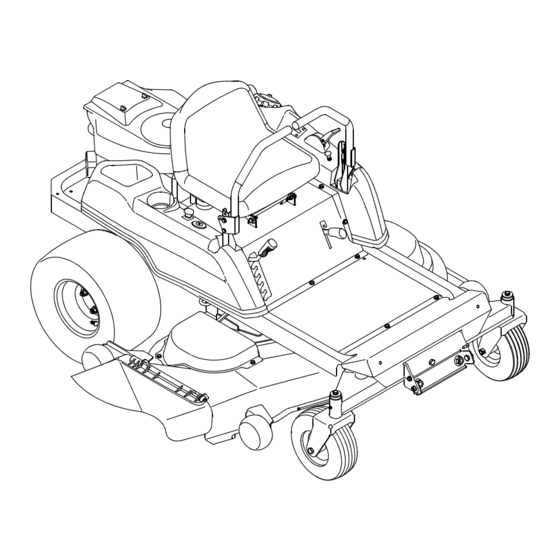
PERATOR'S
ANUAL
RZT SERIES
TRACTOR
Model Number
RZT 22
w/50" Mower Deck
IMPORTANT: READ SAFETY RULES AND INSTRUCTIONS CAREFULLY
Warning:
This unit is equipped with an internal combustion engine and should not be used on or near any unimproved forest-
covered, brush-covered or grass-covered land unless the engine's exhaust system is equipped with a spark arrester meeting
applicable local or state laws (if any). If a spark arrester is used, it should be maintained in effective working order by the operator.
In the State of California the above is required by law (Section 4442 of the California Public Resources Code). Other states may have
similar laws. Federal laws apply on federal lands. A spark arrester for the muffler is available through your nearest engine authorized
service dealer or contact the service department, P.O. Box 361131 Cleveland, Ohio 44136-0019.
CUB CADET LLC P.O. BOX 361131 CLEVELAND, OHIO 44136-0019 [www.cubcadet.com]
PRINTED IN U.S.A.
FORM NO. 769-01126
(2/04)
Advertisement
Table of Contents

Related Manuals for Cub Cadet RZT 22


Summary of Contents for Cub Cadet RZT 22
-
Page 1: Model Number
Federal laws apply on federal lands. A spark arrester for the muffler is available through your nearest engine authorized service dealer or contact the service department, P.O. Box 361131 Cleveland, Ohio 44136-0019. CUB CADET LLC P.O. BOX 361131 CLEVELAND, OHIO 44136-0019 [www.cubcadet.com] PRINTED IN U.S.A. -
Page 2: Table Of Contents
TABLE OF CONTENTS TRACTOR PREPARATION ....................2 IMPORTANT SAFE OPERATION PRACTICES ..............3 SAFETY DECALS AND LABELS .................... 6 TO THE OWNER ........................8 CALLING SERVICE INFORMATION ..................8 RECORDING MODEL AND SERIAL NUMBER INFORMATION ........... 8 SECTION 1: CONTROLS AND FEATURES ................9 SECTION 2: OPERATION .................... -
Page 3: Important Safe Operation Practices
WARNING • The engine exhaust, some of its constituents, and certain vehicle components contain or emit chemicals known to the State of California to cause cancer, birth defects or other reproductive harm. • This unit is equipped with an internal combustion engine and should not be used on or near any unimproved forest-covered, brush-covered, or grass-covered land unless the engine’s exhaust system is equipped with a spark arrester meeting applicable local or state laws (if any). - Page 4 III. CHILDREN 22. Use only accessories approved for this machine Tragic accidents can occur if the operator is not alert by Cub Cadet. Read, understand and follow all to the presence of children. Children are often instructions provided...
- Page 5 5. Never allow children under 14 years old to 8. After striking a foreign object, stop the engine, operate the machine. Children 14 years and over remove the wire from the spark plug and should only operate the machine under close thoroughly inspect the mower for any damage.
-
Page 6: Safety Decals And Labels
SAFETY DECALS AND LABELS Keep product safety graphics (decals) clean. Replace any safety graphic that is damaged, destroyed, missing, paint- ed over or can no longer be read. Replacement safety graphics are available through your dealer. START REVERSE FORWARD NEUTRAL STARTING INSTRUCTIONS FOR FIRST-TIME OPERATORS To START, PARK BRAKE must be set. - Page 7 SAFETY DECALS AND LABELS WARNING TO R ED U CE TH E R IS K O F IN JU R Y, D O N O T O PER ATE U N L ES S D IS CH AR G E CO VER O R GRASS CATCH ER IS IN ITS PR O PER PL ACE.
-
Page 8: To The Owner
LEVEL SURFACE before pulling the transmission bypass rods to the engaged position (transmission disengaged). Your local authorized Cub Cadet dealer is interested in the performance you receive from your tractor, and with the maintenance needed to ensure the satisfactory operation of your tractor. The dealer has trained service personnel familiar with the latest servicing information, is equipped with the latest tools, and has a complete line of genuine Cub Cadet service parts which assure proper fit and high quality. -
Page 9: Section 1: Controls And Features
SECTION 1: CONTROLS AND FEATURES Figure 3 Deck Height Index Storage Tray Deck Lift Handle Seat Adjustment Wing Knobs (Not Shown) RH and LH Drive Control Levers Fuel Tank Cap Ignition Switch Hour Meter /Indicator Panel PTO Switch Throttle Control Transmission Bypass Rod (Not Shown) Choke Control O. - Page 10 NOTE: START- The starter motor will turn over the engine. References to LEFT, RIGHT, FRONT, and Release the key immediately when the REAR indicate that position on the tractor when engine starts facing forward while seated in the operator’s seat. NOTE: To prevent accidental starting and/or battery A.
- Page 11 Indicator and check for possible causes. Do not run the engine while this indicator is illuminated. Contact your Cub Cadet dealer to have the tractor and engine inspected. NOTE: The oil pressure indicator may illuminate when the ignition switch is in the ON position, but should turn off when the engine is started.
-
Page 12: Section 2: Operation
M. Throttle Control N. Choke Control The throttle control is located on the LH console to The choke knob controls the position of the engine the left of the operator’s seat. When set in a given choke. Pull the knob out to choke the engine; push the position, a uniform engine speed will be maintained. - Page 13 Out in Neutral Out in Neutral system should ever malfunction, do not operate the Parking Brake tractor. Contact your authorized Cub Cadet Dealer. Engaged • The safety interlock system prevents the engine from cranking or starting unless the RH and LH...
- Page 14 Have the tractor discharge if the equipment is left unattended. inspected by your Cub Cadet dealer. PRACTICE OPERATION (INITIAL USE) COLD WEATHER STARTING Be sure to use the proper oil for the expected...
- Page 15 • Adjust operator’s seat most comfortable position that allows you to operate DRIVING FORWARD the controls. See seat adjustment in the Faster ADJUSTMENTS section. • Release the parking brake. • Move the RH and LH drive control levers inward Slower in the neutral position.
- Page 16 - To turn to the right, move the right drive control IMPORTANT: Always maintain your grasp on the lever rearward of the left lever. See Figure 12. drive control levers. Do not release the levers to slow the tractor or to return to neutral. FORWARD RIGHT TURN Turning While Driving Rearward •...
- Page 17 Executing a Zero Turn STOPPING THE TRACTOR WARNING: When executing a zero turn, • Move both drive control levers to the neutral tractor MUST STOPPED. position to stop the motion of the tractor. Executing a zero turn while the tractor is •...
- Page 18 If a safety circuit is mowed is free of debris, sticks, stones, not working as designed, contact you Cub Cadet wire or other objects that can be thrown dealer to have the tractor inspected. DO NOT operate by the rotating blades.
-
Page 19: Section 3: Adjustments
SECTION 3: ADJUSTMENTS ADJUSTING THE OPERATORS SEAT • Remove the two hex insert lock nuts securing the hex cap screws fastening the control lever to the The seat may be adjusted fore and aft for the comfort control pivot bracket. Refer to Figure 19. of the operator. -
Page 20: Section 4: Maintenance
• Remove the hex cap screw and sems nut secur- be performed by your Cub Cadet dealer. ing the red positive battery lead to the positive battery post (marked POS). GENERAL BATTERY INFORMATION •... - Page 21 • Using a pressure lubricating gun, lubricate the BATTERY MAINTENANCE front castor axles with Cub Cadet 251H EP The battery is filled with battery acid and then sealed grease after every 10 hours of service. at the factory. However, even a “maintenance free”...
- Page 22 • Remove the internal cotter pin securing the ferrule to the transmission control arm and withdraw the ferrule. Wheel rotation should stop. If it does not, contact your Cub Cadet dealer. Keyhole Slot • If the rotation stops, adjust the ferrule up or down the control rod as necessary to align with the hole in the transmission control arm.
- Page 23 • Locate the applicable stop bolt on the left or right Transmission console. See Figure 24. Drive Pulley Idler Pulley Console Jam Nut Square Stop Bolt Drive Hole Belt Idler Bracket Pulley Engine Pulley Idler Brkt. Spring Figure 25 Figure 24 •...
- Page 24 TRACTOR STORAGE • Fill the fuel tank with treated fuel and run the engine for 2-3 minutes to get stabilized fuel into If your tractor is not going to be operated for an the carburetor. extended period of time (thirty days to approximately six months), the tractor should be prepared for stor- Emptying the fuel system: age.
-
Page 25: Section 5: Mower Deck
SECTION 5: MOWER DECK This section contains removal, installation, adjust- Rear Deck ment, and maintenance information for the 50-inch Deck Lift Arm Hanger Bracket mower deck. Instructions for installation and removal of the optional mulching plug are located at the end of this section. - Page 26 • Use the deck lift handle of the tractor to lower the deck lift arms into the slots of the rear deck hanger brackets. • Pull the deck support pins outward and maneuver the deck as necessary to align the holes in the deck lift arm with the pins.
- Page 27 • Loosen the two hex jam nuts and turn them away Shoulder from the backside of the front hanger rod bracket. Screw • If the front of the deck was too low, turn the hex Front Gauge Gauge Wheel flange nuts on the ends of the front hanger rod Rear Gauge Wheel clockwise to raise the front of the deck.
- Page 28 • Use a 15/16 inch wrench to hold the hex nut on DECK LUBRICATION top of the spindle assembly when loosening the • After every 10 hours of operation and/or before hex nut securing the blade. A block of wood may putting the deck into winter storage, lubricate be placed between the deck housing and the the spindle assemblies with 251H EP grease or...
-
Page 29: Slope Gauge
SLOPE GAUGE (Keep this sheet in a safe place for future reference.) -
Page 31: Engine Manual
Read this manual in its entirety. Observe all warnings and follow all operation and maintenance instructions pro- vided in the manual. However, if you experience any engine problems, or have any questions regarding your engine, contact your Cub Cadet dealer first. - Page 32 Operating & Maintenance Instructions Model Series Covered in This Manual 400000 440000 Model Type Code Note: General Model Series numbers noted above are inclusive of the specific mod- Month Day Year el number found on your engine. To get replacement parts or technical assistance in the future, write your engine Model, Type, Code and date of purchase here.
- Page 33 The Power That Works For You. Look For Relevant Emissions Durability Period and Air Index Information On Your Engine Emissions Label Engines that are certified to meet the California Air Resources Board (CARB) Tier 2 Emission Standards must display information regarding the Emissions Durability Period and the Air Index. Briggs & Stratton makes this information available to the consumer on our emission labels.
- Page 34 275475 BEFORE OPERATING ENGINE • Read entire Operating & Maintenance Instructions AND the instructions for the equipment this engine powers.* • Failure to follow instructions could result in serious injury or death. THE OPERATING & MAINTENANCE INSTRUCTIONS CONTAIN SAFETY INFORMATION TO •...
- Page 35 SAFETY WARNING WARNING Starting engine creates sparking. Gasoline and its vapors are extremely flammable and explosive. Sparking can ignite nearby flammable gases. Fire or explosion can cause severe burns or death. Explosion and fire could result. WHEN ADDING FUEL • If there is natural or LP gas leakage in area, do not start engine.
-
Page 36: Engine Information
SAFETY WARNING WARNING Engines give off carbon monoxide, an Unintentional sparking can result in fire or odorless, colorless, poison gas. electric shock. Breathing carbon monoxide can cause nausea, fainting or death. Unintentional start-up can result in en- tanglement, traumatic amputation, or lac- •... - Page 37 ENGINE INFORMATION 1. Rotating screen 9. Intake manifold 2. Oilfill/Dipstick 10. Choke control bracket 3. 12V electric starter 11. Carburetor 4. Fuel filter (if equipped) 12. Throttle control bracket 5. Oil drain plug 13. Engine Model Type Code 6. Spark plug wire xxxxxx xxxx xx xxxxxxxx...
- Page 38 275475 SAE Viscosity Grades CAUTION: This engine is shipped from Briggs & Stratton without oil. Check oil level before starting engine. If you start the engine without oil, the engine will be damaged beyond repair and will not be covered under warranty. OIL CAPACITY °...
- Page 39 FUEL • This engine is certified to operate on gasoline. Exhaust TYPE OF FUEL TO USE Emission Control System: EM (Engine Modifications). • Use clean, fresh, regular unleaded gasoline with a minimum of 85 octane. Fresh fuel prevents gum from CAUTION: Some fuels, called oxygenated or reformu- forming in the fuel system or on essential carburetor parts.
-
Page 40: Starting And Stopping
STARTING AND STOPPING ELECTRIC (KEY) STARTER TO START ENGINE FULL Ï Ï Ï Choke [2] Open fuel shut-off valve Ï (if equipped). [4] Move throttle (if equipped) to FAST. Operate engine with [3] Move choke control to throttle in FAST. CHOKE or START. - Page 41 MAINTENANCE MAINTENANCE EMISSION CONTROL Regular maintenance will improve the performance and Maintenance, replacement or repair of the emission extend the life of the engine. See any Authorized Briggs & control devices and systems may be performed by any Stratton Dealer for service. Use only genuine Briggs & nonroad engine repair establishment or individual.
-
Page 42: Air Cleaner
MAINTENANCE OIL PRESSURE CHANGING OIL FILTER If oil pressure drops below 4-6 psi (.2-.4 kg/cm ), an oil Change oil filter after every 100 hours or every season. pressure switch (if engine is equipped) will either activate a [1] Drain engine oil and remove oil filter. warning light or stop the engine. - Page 43 MAINTENANCE ENGINE AND ENGINE PARTS We recommend that you see an authorized Briggs & Stratton Service Dealer for all maintenance and service of the engine and engine parts. Use only genuine Briggs & Stratton parts. If you perform any maintenance on the engine, first disconnect the spark plug wires WARNING from the spark plugs, and disconnect the battery at the negative terminal (electric starter engines only) to prevent unintentional sparking.
- Page 44 MAINTENANCE CLEANING DEBRIS ROTATING SCREEN CAUTION: Do not use water to clean engine parts. Water could contaminate fuel system. Use a brush or dry cloth. Engine parts should be kept WARNING clean to reduce the risk of overheating and ignition of accumulated debris.
-
Page 45: Carburetor Adjustment
ADJUSTMENTS CARBURETOR ADJUSTMENT TO ADJUST REMOTE THROTTLE CONTROL If the engine does not start or if it runs roughly, the remote WARNING throttle control may need adjustment. See your authorized Briggs & Stratton dealer or follow the instructions below. The manufacturer of the equipment on which this engine is installed specifies top speed at which the engine will be operated. - Page 46 SERVICE & STORAGE PARTIAL LIST OF GENUINE BRIGGS & An illustrated shop manual includes common specifications and detailed in- STRATTON PARTS formation covering adjustment, tune-up and repair of Briggs & Stratton twin BRIGGS & STRATTON cylinder, OHV, 4 cycle engines. It is PART PART NO.
- Page 47 SERVICE & STORAGE STORAGE [2] While engine is still warm, change oil. Engines stored over 30 days need special attention. [3] Remove spark plugs and pour about 1 oz. (30 ml) of engine oil into each cylinder. Replace spark plugs and [1] To prevent gum from forming in fuel system or on crank slowly to distribute oil.
-
Page 48: Limited Warranty
LIMITED WARRANTY Briggs & Stratton Corporation will repair or replace, free of charge, any part(s) of the engine that is defective in material or workmanship or both. Transportation charges on parts submitted for repair or replacement under this warranty must be borne by purchaser. This warranty is effective for the time periods and subject to the conditions stated below. -
Page 49: Warranty
EMISSION CONTROL WARRANTY COVERAGE IS APPLICABLE TO CERTIFIED ENGINES PURCHASED IN CALIFORNIA IN 1995 AND THERE- AFTER, WHICH ARE USED IN CALIFORNIA, AND TO CERTIFIED MODEL YEAR 1997 AND LATER ENGINES WHICH ARE PURCHASED AND USED ELSEWHERE IN THE UNITED STATES (AND AFTER JANUARY 1, 2001 IN CANADA). The California Air Resources Board (CARB), U.S. - Page 50 • • • • • • • • • • • • INFORMATIONS IMPORTANTES CORPORATION BRIGGS & STRATTON FAMILLE YBSXS.3192VA 274812 CE MOTEUR EST CONFORME AUX NORMES ANTIPOLLUTION 2000 – 2001 DE CALIFORNIE POUR LES PETITS MOTEURS HORS ROUTE ET AUX NORMES ENVIRONNEMENTALES AMÉRICAINES (EPA PHASE 2) POUR LES PETITS MOTEURS HORS ROUTE.
- Page 52 MANUFACTURER’S LIMITED WARRANTY FOR: The limited warranty set forth below is given by Cub Cadet Cub Cadet does not extend any warranty for products LLC with respect to new merchandise purchased and used in sold or exported outside of the United States, its the United States, its possessions and territories.