Table of Contents
Advertisement
Available languages
Available languages
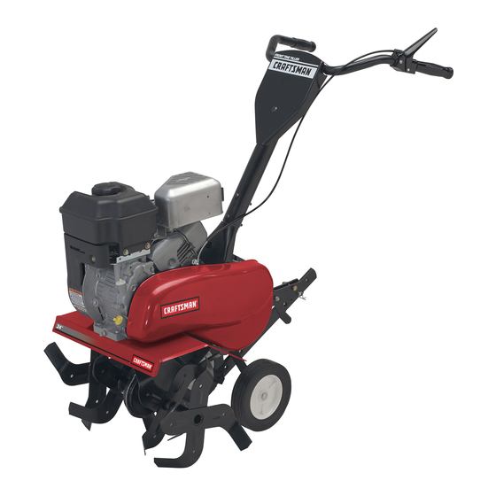
Owner's Manual
CRRFTSMRN°
F
TT
E TILLE
900 Series
24 Inch Tine Width
Model No.
917.299011
• EspaSol,
p. 20
This product has a low emission
engine
which
operates
differently
from
previously
built
engines.
Before
you start the
engine,
read and understand
this Owner's
Manual.
IMPORTANT."
Read and follow all Safety
Rules and Instructions before
operating this equipment.
Sears, Roebuck and Co., Hoffman Estates, IL 60179 U.S.A.
Visit our Craftsman website:www.sears.com/craftsman
425340
Rev. 3
Advertisement
Table of Contents

Related Manuals for Craftsman 917.299011


Summary of Contents for Craftsman 917.299011
- Page 1 Before you start the engine, read and understand this Owner's Manual. IMPORTANT." Read and follow all Safety Rules and Instructions before operating this equipment. Sears, Roebuck and Co., Hoffman Estates, IL 60179 U.S.A. Visit our Craftsman website:www.sears.com/craftsman 425340 Rev. 3...
- Page 2 Schedule ......Sears Service ......Back Cover LIMITED ONE YEAR WARRANTY ON CRAFTSMAN TILLER For one (1) year from date of purchase, when this Craftsman Tiller is maintained, lubricated, and tuned up according to the operating and maintenance instructions in the owner's manual, Sears will repair free of charge any defect in material or workmanship.
- Page 3 * Use extension cords and receptacles • Do not overload the machine capacity as specified by the manufacturer for al! by attempting to till too deep at too fast units with electric drive motors or elec- a rate. tric starting motors. •...
- Page 4 (Gap: .030") AGREEMENTS Congratulations on making a smart pur- CONGRATULATIONS on your purchase chase. Your new Craftsman@ product is of a Sears Tiller. It has been designed, designed and manufactured for years of engineered and manufactured to give you dependable operation. But like all products,...
- Page 5 These accessories were available when the tiller was produced. They are also available at most Sears retail outlets and service centers. Some of these accessories may not apply to your tiller. ENGINE SPARK PLUG MUFFLER AIR FILTER GAS CAN ENGINE OIL STABILIZER TILLER MAINTENANCE...
- Page 6 Your new tiller has been assembled at the factory with the exception of those parts left unassembled for shipping purposes. To ensure safe and proper operation of your tiller all parts and hardware you assemble must be tightened securely. Use the correct tools as necessary to insure proper tightness.
- Page 7 KNOW YOUR TILLER READ THIS OWNER'S MANUAL AND SAFETY RULES BEFORE OPERATING YOUR TILLER Compare the illustrations with your tiller to familiarize yourself with the locations of var- ious controls and adjustments. Save this manual for future reference. txt ' FILLING FORWARD NEUTRAL...
- Page 8 The operation of any tiller can result in foreign objects thrown into the eyes, which can result in severe eye damage. Always wear safety glasses or eye shields before starting your tiller and while tilling. We recommend standard safety glasses or a wide vision safety mask worn over spectacles. HOW TO USE YOUR TILLER TILLING Know how to operate all controls before...
- Page 9 AROUND TOWN _f_CAUTION: Fill to within 1/2 inch of top 1. Disconnectspark plug wire. of fuel tank to prevent spills and to allow 2. Drain fuel tank. for fuel expansion. If gasoline is acci- 3. Transportin upright position to prevent dentally spilled, move machine away from oil leakage.
- Page 10 7. If the choke lever has been moved to ., Tilling is digging into, turning over, and the "ON" position to start the engine, breaking up packed soil before planting. gradually move it to the opposite posti- Loose, unpacked soil helps root growth. ion as the engine warms up.
- Page 11 CULTIVATING Cultivating is destroyingthe weeds be- tween rows to preventthem from robbing nourishmentand moisturefrom the plants. At the same time, breaking up the upper layer of soil crustwill help retain moisture in the soil. Best digging depth is 1"-3". • You will probably not need to use the depth stake.
- Page 12 / / / / / MAINTENANCE SERVICE DATES REGULAR SERVICE _ _'_'_'_ #_'x _'_'_ Check Engine 0il Level Change Engine Oil _1,2 Oil Pivot Points Inspect Spark Arrester / Muffler Inspect Air Screen Clean or Replace Air Cleaner Cartridge Clean Engine Cylinder Fins Replace Spark Plug 1 - Change more often when operating under a heavy load or in high ambient temperatures.
- Page 13 5. Refill engine with oil. See "FILL Al:_CAUTION:Disconnect spark plug wire ENGINE WITH OIL" in the Operation before performing any maintenance section of this manual. prevent accidental starting of engine. Prevent fires! Keep the engine free of grass, leaves, spilled oil, or fuel. Remove fuel from tank before tipping unit for main- Drain tenance.
- Page 14 COOLING SYSTEM SPARK PLUG Your engine is air cooled. For proper en- Replace spark plugs at the beginning of gine performance and long life keep your each tilling season or after every 25 hours engine clean. of use, whichever comes first. Spark plug •...
- Page 15 * Assemble holes '_' in tine hubs to holes AI:_CAUTION: Disconnect spark plug wire "C" in tine shaft. from spark plug and place wire where it cannot come into contact with plug. TILLER _.Ac ?,.. TO ADJUST HANDLE HEIGHT Io® ®o Factory assembly has provided lowest...
- Page 16 TO REPLACE V-BELT 5. With tine control "ON" (held down to handle) push down on handle to raise Replace V-belt if it has stretched consid- tines off the ground. erably or if it has cracks or frayed edges. 6. Slowly pull recoil starter handle while 1.
- Page 17 Immediately prepare your tiller for storage NOTE: Fuel stabilizer is an acceptable at the end of the season or if the unit will alternative in minimizing the formation of not be used for 30 days or more. fuel gum deposits during storage. _i, Warning: Never store the tiller with gas- stabilizer to gasoline in fue! tank or stor-...
- Page 18 TROUBLESHOOTING CHART: See appropriate section in manual unless directed to Sears service center CORRECTION PROBLEM CAUSE Fill fuel tank. Will start Out of fuel. Fuel valve "OFF" Turn fuel valve to the "ON" position. Engine Switch "OFF" Turn engine switch to the "ON" position. Engine not "CHOKED"...
- Page 19 TROUBLESHOOTING CHART: See appropriate section in manual unless directed to Sears service center CORRECTION PROBLEM CAUSE Excessive Ground too dry and hard. Moisten ground or wait for more favorable soil conditions bounce/ difficult Wheels and depth stake Adjust wheels and depth stake. handling incorrectly adjusted.
- Page 20 • Si la Cultivadora Craftsman se usa para fines de arriendo, esta garantia se aplica solamente treinta (30) dias a partir de la fecha de compra. El Servicio de Garantia esta disponible al devolver la cultivadora Craftsman al centro/departa- mento de servicio Sears m_flscercano en los Estados Unidos.
- Page 21 OPERACION * Use solamente accesorios y aditamentos para la cultivadora aprobados por el fabrican- • No ponga ni las manos ni los pies cerca o debajo de las piezas rotatorias. Nunca opere la cultivadora sin buena visibili- • Tenga mucho cuidado cuando opere o cruce dad o luz.
- Page 22 Capacidad de 3 Cuartos Congratulaciones por su buena compra. Gasolina: Sin plomo, Regular Su nuevo producto Craftsman® esta disefiado Aceite (API-SG-SL): SAE 30 (Sobre 32°F) y fabricado para funcionar de modo liable por (Capacidad: 16 oz.) SAE 5W-30 (Debajo 32°F) muchos afios.
- Page 23 Estos accesorios estaban disponibles cuando se produjo la cultivadora. Tambien estan disponibles en la mayorfa de las tiendas de Sears y en los centros de servicio. Algunos de estos accesorios tal vez no se apliquen a su cultivadora. MOTOR BUJJA SILENCIADOR FILTRO DE AIRE...
- Page 24 Su cultivadora nueva ha sido montada en la fabrica, con la excepci6n de aquellas partes que se dejaron sin montar pot razones de envio. Para asegurarse que la cultivadora operara en forma segura y adecuada, todas las partes y los articulos de ferreteria que monte tienen que estar apre- tados en forma segura.
- Page 25 CONOZCA SU CULTIVADORA LEA ESTE MANUAL DEL DUENO Y LAS REGLAS DE SEGURIDAD ANTES DE OPERAR SU CUTIVADORA Compare las ilustraciones con su cultivadora para familiarizarse con la ubicaci6n de los diversos controles y ajustes. Guarde este manual para referencia en el futuro. Estos simbolos pueden apareser sobre su cultivadora...
- Page 26 La operaci6n de cualquier cultivadora puede hacer que salten objetos extrafios dentro de sus ojos, Io que puede producir dafios graves en estos. Siempre use anteojos de seguridad o protecciones para los ojos antes de hacer arrancar su cultivadora o mientras este labrando con ella.
- Page 27 ENLA ClUDAD 4f_PRECAUCI6N: Llene el estanque de 1. Desconecte el alambre de la bujia. combustible hasta dentro de 1/2 pulgada de la 2. Dreneel estanque decombustible. parte superior para evitar los derrames y para 3. Transp6rtela e n la posici6n derechahacia permitir que se expanda el combustible.
- Page 28 Siesta forzandola o si la cultivadora esta vibrando, NOTA: si el motor enciende pero no quiere decir que las ruedas y la estaca de profun- arranca, mueva el control del obturador didad no estan ajustadas en forma adecuada para hasta la mitad de la posici6n del obtura- el terreno que se esta labrando.
- Page 29 CULTIVO El cultivo q uieredecir ladestrucci6n de lamala hierbaentrelasfilas p ara evitar que @stas le roben lanutrici6n y lahumedad a lasplantas. AI mismo tiempo,sise rompe lacapa superior de lacostradelsuelo, @ste puede retener la humedad. La mejor profundidad de excavaci6n es de l"a 3".
- Page 30 PROGRAMA MANTENIMIENTO LLENE LAS FECHAS DE MEDIDA COMPLETE FECHAS DE SERVICIO SERVICIO REGULAR Revisar et nivet del aceite del motor Cambiar et aceite del motor Aceitar los puntos de pivote lnspeccionar et supresor del sitenciador lnspeccionar la rejitta de aire Limpiar/cambiar et cartucho del fittro de aire...
- Page 31 Incline la cultivadora hacia adelante para _PRECAUCl6N: Desconecte el alambre de drenar el aceite. la bujia antes de dar mantenimiento (excepto Despues de que el aceite se haya drenado pot el ajuste del carburador) para evitar que el completamente, vuelva a colocar el tap6n motor arranque pot accidente.
- Page 32 SISTEMA DEENFRIAMIENTO BUJiA Su motorse enfdaconaire.Paraobtener el Cambie las bujias al comienzo de cada rendimiento d elmotoradecuado y larga temporada de cultivo, o despues de 50 horas duraci6n mantenga su motorlimpio. de uso, Io que suceda primero. El tipo de bujia •...
- Page 33 LABRADO DE ANCHO MEDIANO- PASO DE 22" ,I_PRECAUCl6N: Desconecte el alambre de la bujia y p6ngalo en donde no pueda entrar en * Monte los agujeros 'A" en los cubos de los contacto con la bujia. brazos con los agujeros "C" en el eje de los CU LTWADORA brazos.
- Page 34 REVISION FINAL EN LA POSICION DE "EN= PARA CAMBIAR LA CORREA V CambJe la correa V si se ha estirado consid= CENDIDO" (ON) erablemente o si esta partida o si los bordes Con el control de los brazos en la posicJ6n estan desgastados.
- Page 35 AVlSO: El estabilizador de combustible es una Inmediatamente prepare su cultivadora para el almacenamiento al final de la temporada o si la alternativa aceptable para reducir a un minimo unidad no se va a usar pot 30 dfas o mas. la formaci6n de dep6sitos de goma en el com= ,II_PRECAUCl6N:...
- Page 36 IDENTIFICACION DE PROBLEMAS: Yea la seccion apropiada en el manual a menos que este dirigido a un centro de servicio Sears. CORRECCION PROBLEMA CAUSA No arranca Se acab6 et combustible. Llene et tanque de combustible. La valvula de combustible esta en Gire la valvula de combustible hasta la la posici6n <<OFF>>...
- Page 37 IDENTIFICACION DE PROBLEMAS: Vea la seccion apropiada en el manual a menos que este dirigido a un centro de servicio Sears. PROBLEMA CAUSA CORRECCION Controle et nivel de aceite/cambie et aceite. El motor Et nivel de aceite esta bajo/el recalienta aceite esta sucio.
- Page 38 TILLER - - MODEL NUMBER 917.299011 HANDLES KEY PART KEY PART DESCRIPTION DESCRIPTION 137118 72010520 Bott 5/16-18 x 2-1/2 Panel, Control 165787 Grip, Handle 73970500 Locknut, Flange 5/16-18 unc 98000129 Nut, Flange 431332 Assembly, Handle Column STD533107 Bolt, Carriage 5/16-18 x 3/4 181580 Clip 181476...
- Page 39 TILLER = = MODEL NUMBER 917.299011 BELT GUARD AND PULLEY ASSEMBLY beltguard PART PART DESCRiPTiON DESCRIPTION 23230506 Screw Set 5/16-18 x 3/8 Patch 12000028 Ring, Retainer 130812 Sheave, Engine 151223 Sheave, Transmisison 86777 Screw, Tap Hex Head 12000036 Ring, Ktip 74770508 Bolt, Hex Head 5/16-24 unfx 1/2 STD541237...
- Page 40 TILLER - - MODEL NUMBER 917.299011 WHEEL AND DEPTH STAKE ASSEMBLY wheehd.stake 2 r2 KEY PART KEY PART DESCRIPTION DESCRIPTION 9194R Pin, Clevis 121117X Bolt, Shoulder 193851X613 Wheel 74760520 Bolt, Hex Head 5/16-18 x 1-1/4 STD523107 9190R Bracket, Wheel Bolt, Hex Head 5/16-18 x 3/4 73220500 STD541437 Locknut, Crown 3/8-16...
- Page 41 TILLER = = MODEL NUMBER 917.299011 TINE ASSEMBLY tine_ipb_3 KEY PART KEY PART DESCRiPTiON DESCRiPTiON 156926 Tine, Outer, R.H. 156925 Tine, Outer, L.H. 3146R 4929H Pin, Clevis Retainer, Spring Zinc 156924 Tine, Inner, R.H. NOTE: All component dimensions given in U.S.inches. 156923 Tine, Inner, L.H.
- Page 42 TILLER = = MODEL NUMBER 917.299011 TRANSMISSION transmission LCT 1 KEY PART PART DESCRIPTION DESCRIPTION 73970500 74760524 Bolt, Hex 5/16-18 x 1-1/2 Gr. 2 Nut, Lock Hex Flange 5/16-18 STD523732 Bolt, Fin, Hex 3/8-16 x 3-1/4 uric STD551037 Washer 13/32 x 13/16 x 11 19091412 Washer 9/32 x 7/8 x 12 Ga.
- Page 43 TILLER - - MODEL NUMBER 917.299011 DECALS PART DESCRIPTION 423884 Decal, LCT900 425502 Decal, Bettguard 425503 Decal, Tine Shield 137539 Decal, Cntrl Phi Inst. 120431X Decal, Hand Placement 162215 Decal, Tine, Shield, Warning 120075X Decal, Warning, Rotating Tines 425501 Decal, Console 425340 Manual, Owner's (Eng/Span)
- Page 44 TILLER - - MODEL NUMBER 917.299011 ENGINE, LCT ==MODEL NUMBER PLMHKI4600124P=BPQE2 208cc SERVICE KIT BREAKDOWN °X_¸ _...
- Page 45 TILLER = = MODEL NUMBER 917.299011 ENGINE, LCT ==MODEL NUMBER PLMHKI4600124P=BPQE2 KEY PART DESCRiPTiON 420578 Cylinder Head Service Kit Sk208-1000 420579 Push Rod Service Kit Sk208-1001 420580 Valve Cover Service Kit Sk4500 420581 Cylinder Service Kit Sk208-1300 420582 Piston Service Kit Sk208-1400 420583 Connecting Rod Service Kit Sk208-1500...
- Page 48 NEED MORE YOu/i fk@,, the a_swer and re©re on managemyh, o_eocem,, _ fo__free! o Find this andaKyour other product m anualsonline, o Get answersfrom our team of homeexperts. o Get a personalizedmaintenanceplan for your home. o Fnd information and tooB to help with homeprojects. II i a sge hOllme Your Home...