Table of Contents
Advertisement
®
Installation, Operation and Maintenance Manual
Please read and save these instructions. Read carefully before attempting to assemble, install, operate or maintain the
product described. Protect yourself and others by observing all safety information. Failure to comply with instructions
could result in personal injury and/or property damage! Retain instructions for future reference.
General Safety Information
Only qualified personnel should install this unit.
Personnel should have a clear understanding of these
instructions and should be aware of general safety
precautions. Improper installation can result in electric
shock, possible injury due to coming in contact with
moving parts, as well as other potential hazards.
Other considerations may be required if high winds
or seismic activity are present. If more information
is needed, contact a licensed professional engineer
before moving forward.
1. Follow all local electrical and safety codes, as well
as the National Electrical Code (NEC), the National
Fire Protection Agency (NFPA), where applicable.
Follow the Canadian Electrical Code (CEC) in
Canada.
2. The rotation of the wheel is critical. It must be free
to rotate without striking or rubbing any stationary
objects.
3. Motor must be securely and adequately grounded.
4. Do not spin fan wheel faster than the maximum
cataloged fan rpm. Adjustments to fan speed
significantly affects motor load. If the fan RPM is
changed, the motor current should be checked to
make sure it is not exceeding the motor nameplate
amps.
5. Do not allow the power cable to kink or come
in contact with oil, grease, hot surfaces, or
chemicals. Replace cord immediately if damaged.
6. Verify that the power source is compatible with the
equipment.
7. Never open blower access doors while the fan is
running.
®
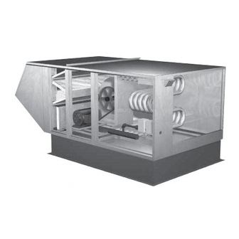
IG/IGX Make-Up Air Unit
DANGER
Always disconnect power before working on or
near a unit. Lock and tag the disconnect switch or
breaker to prevent accidental power up.
CAUTION
When servicing the unit, motor may be hot enough
to cause pain or injury. Allow motor to cool before
servicing.
FOR YOUR SAFETY
If you smell gas:
1. Open windows.
2. Do not touch electrical switches.
3. Extinguish any open flame.
4. Immediately call your gas supplier.
FOR YOUR SAFETY
The use and storage of gasoline or other
flammable vapors and liquids in open
containers in the vicinity of this appliance is
hazardous.
WARNING
Improper installation, adjustment,
alteration, service or maintenance can
cause property damage, injury or death.
Read the installation, operating and
maintenance instructions thoroughly before
installing or servicing this equipment.
Document 470656
Model IG / IGX Make-Up Air
1
Advertisement
Table of Contents

Related Manuals for Greenheck IG


Summary of Contents for Greenheck IG
-
Page 1: General Safety Information
Document 470656 IG/IGX Make-Up Air Unit ® Installation, Operation and Maintenance Manual Please read and save these instructions. Read carefully before attempting to assemble, install, operate or maintain the product described. Protect yourself and others by observing all safety information. Failure to comply with instructions could result in personal injury and/or property damage! Retain instructions for future reference. - Page 2 Receiving moisture build up. Leave coverings loose to permit air circulation and to allow for periodic inspection. Upon receiving the product, check to make sure all items are accounted for by referencing the bill The unit should be stored at least 3½ in. (89 mm) off of lading to ensure all items were received.
-
Page 3: Table Of Contents
3. After storage period, purge grease before putting Sequence of Operation, Furnace – 2:1 Staged ......38 fan into service. -
Page 4: Indoor Unit
Installation of Indoor Unit Installation of Arrangement DB / HZ 1. Install Curb and/or Equipment NOTE Support(s) To prevent premature heat exchanger failure, do not Position curb/equipment support(s) on the roof locate units where chlorinated, halogenated, or acid (reference the CAPS submittal for placement of curb/ vapors are present. -
Page 5: Roof Mounted Unit – Arrangement Dbc
2. Install Combination Curb Adaptor NOTE Install combination curb adaptor over curb, use wood The use of all lifting lugs and a set of spreader bars screws to lag in place. Locate extension so the tall is mandatory when lifting the unit. louvered side is over the exhaust opening, as shown in illustration. -
Page 6: Roof Mounted Unit – Arrangement Dbc
Installation of Roof Mounted Unit 7. Install Supply Unit Use a crane and a set of spreader bars hooked to the Arrangement DBC, continued factory lifting lugs to lift and center the unit on the extension/equipment support(s). 4. Apply Sealant Use self-tapping sheet metal screws to fasten the unit Apply an appropriate sealant around the perimeter of to the extension/equipment support(s). - Page 7 Installation of Evaporative Cooling Installation of Venting for Outdoor Module (optional) Units NOTE 1. Follow Guidelines All of the following guidelines must be followed when Small evaporative coolers ship attached to the base installing the unit. unit and require no additional mounting. 1.
- Page 8 Installation of Venting for Indoor Venting Methods There are three venting methods for indoor mounted Units units. For each method, the units can be vented horizontally through an exterior wall or vertically WARNING through the roof. Specific venting instructions are The following guidelines must be followed for all indoor provided for each method and shown in the following units:...
-
Page 9: Standard Indoor
Installation of Standard Indoor Vent Pipe Diameter Select the vent pipe diameter. Use only the specified Venting pipe diameter. Standard Indoor Venting uses one penetration through an exterior wall or roof for venting the flue exhaust. Furnace Size Exhaust Pipe Diameter (MBH) (inches) The combustion air is supplied from the air inside the... - Page 10 Installation of Concentric Venting Concentric Venting – Horizontal (General) Refer to the diagram below for venting on horizontal concentric systems. Maintain at least 12 inches from Concentric venting allows the exhaust pipe and the combustion air inlet guard to the exhaust vent combustion air pipe to pass through a single hole in terminal (Dim.
- Page 11 3. Install Exhaust Pipe Concentric Venting – Vertical Slide the exhaust pipe through the CVA. Provide Refer to the diagram below for venting on vertical enough exhaust piping to pass through the wall (or concentric systems. Maintain at least 12 inches floor) and provide the minimum clearance of 12 inches between the top of the combustion air inlet terminals between the exhaust pipe termination and the...
- Page 12 2. Attach Mounting Brackets 7. Install Combustion Air Inlet Guard and Exhaust Vent Terminal Attach field-supplied, corrosion resistant, mounting brackets to the CVA using corrosion resistant sheet Slide the combustion air terminal over the vent pipe metal screws. and fasten it to the combustion air pipe. Attach the 3.
- Page 13 Installation of Two Pipe Venting – 2. Install Combustion Air Pipe Run a combustion air pipe from the unit’s combustion Horizontal air intake through the exterior wall to the outdoors. Refer to the diagram below for venting on horizontal The combustion air pipe must terminate at least 12 concentric systems.
- Page 14 Installation of Two Pipe Venting – 1. Install Exhaust Pipe Vertical Run an exhaust pipe from the unit’s combustion exhaust through the roof to the outdoors. The exhaust Refer to the diagram below for venting on vertical pipe must terminate at least 12 inches above the concentric systems.
-
Page 15: Electrical Wiring
Installation - Electrical Wiring 1. Determine the Size of the Main Power Lines The unit’s nameplate states the voltage and the unit’s IMPORTANT total MCA. The main power lines to the unit should be Before connecting power to the unit, read and sized accordingly. - Page 16 6. Wire the Evaporative Cooler (optional) Reference the ladder diagram on the inside of the control center door for correct wiring of the pump and the optional water valves. NOTE Large evaporative coolers may require a separate power supply. 7. Install Economizer Sensors (optional) All economizer options (EC) require an outdoor air temperature or enthalpy sensor to be field installed inside of the weatherhood and field wired to terminals...
-
Page 17: Gas Piping
Installation of Gas Piping 1. Determine the Supply Gas Requirements IMPORTANT The unit’s nameplate states the requirements for the gas being supplied to the unit. All gas piping must be installed in accordance Minimum gas pressure for maximum output with the latest edition of the National Fuel Gas Code ANSI/Z223.1 and any local codes that may apply. - Page 18 Installation - Evaporative Cooler Piping (optional) Evaporative Cooling with Recirculating Pump Evaporative Cooling with Auto Drain and Fill Supply Line Supply Line Sump Overflow VALVE A Supply Line Valve Supply Solenoid (by others) Drain Line Valve Sump Drain (by others) (by others) VALVE C Drain Line...
- Page 19 1. Install the Water Supply Line Installation of Water Wizard (optional) Supply line opening requirements vary by unit size Evaporative Cooling with the Water Wizard™ and arrangement and are field-supplied. Connect the water supply line to the float valve through the supply NOTE line opening in the evaporative cooling unit.
- Page 20 Installation of Water Wizard™, Installation - Direct Expansion (DX) Coil Piping (optional) continued To Media IMPORTANT Pressure Gauge Guidelines for the installation of direct expansion Factory Installed cooling coils have been provided to ensure proper performance and longevity of the coils. These are Sump Drain general guidelines that may have to be tailored Manual Supply Valve...
- Page 21 for one minute, the system is ready to be charged or NOTE refrigerant in another portion of the system can be If a hot gas bypass kit was provided by others, refer opened to the coil. A steady rise in microns would to the manufacturer’s instructions.
- Page 22 Installation of Chilled Water Coil Installation of Building Pressure Piping (optional) Control (optional) 1. Mount Pressure Tap IMPORTANT Using the factory provided bracket, mount the Guidelines for the installation of the cooling coil pressure tap to the have been provided to ensure proper performance outside of the unit.
-
Page 23: Blower
Start-Up - Blower NOTE Refer to the Start-Up Checklist in the Reference To reverse the rotation on three phase units, Section Before Proceeding Further! disconnect and lock-out the power, then interchange any two power leads. Pre Start-Up Check Rotate the fan wheel by hand and make sure no NOTE parts are rubbing. -
Page 24: Blower
NOTE The most accurate way to measure the air volume is by using a pitot traverse method downstream of the blower. Other methods can be used but should be proven and accurate. IMPORTANT Changing the air volume can significantly increase the motor’s amps. -
Page 25: Single Stage
Start-Up - Furnaces (all units) Available Control Options Single Furnace Units IMPORTANT 1:1 Staged one 1-stage furnace For the unit to function properly, all stage or 2:1 Staged one 2-stage furnace modulation valves must be set for high and low fire. 8:1 Staged one 8-stage furnace 2:1 Electronic... -
Page 26: Staged
Start-Up - 2:1 Staged Control Start-Up - 8:1 Staged Control 1. Send Unit to High Fire IMPORTANT Send the unit to high fire by setting 8:1 staged furnaces use two manifolds and two the temperature selector to its staged gas valves per furnace. The high and low fire Temperature maximum setting. -
Page 27: Staged
6. Access the Discharge Air High Fire High Fire Low Fire Temperature Setting Adjustment Adjustment Terminal Using the Up or Down key, scroll through the Setpoints Menu until the display reads “dtS”, then press the Enter key. The display will change to the discharge air temperature setting. - Page 28 10. Access the Room Override Setting From the Setpoints Menu, use the Up or Down key to navigate through the menu options until the display reads “rot.” Once the display reads “rot,” press the Enter key. The display will change to the room override setting.
-
Page 29: Modulation
Start-Up - 2:1 Electronic Modulation NOTE 1. Send Unit to High Fire The low fire manifold pressure should always be rechecked after adjusting the high fire. Turn the temperature Temperature selector to its maximum NOTE Selector setting to send the unit Once the high and low fire manifold pressures are to high fire. -
Page 30: Modulation
Start-Up - 4:1 Electronic Modulation To enter the high fire setting mode, press and hold button #1 1. Send the Unit to High Fire until the LED lights To send the unit to high fire, press and hold the Up, solid red. - Page 31 10. Edit the Setting Note: If the valve remains in the low fire setting mode Use the Up or Down key to edit the inlet air setting. for more than five (5) minutes, it will revert back to its When the correct setting is displayed, press the Enter previous setting.
- Page 32 Start-Up - Economizer (optional) IMPORTANT The outside air volume must be measured and NOTE compared to the total air volume when setting To prevent premature heat exchanger failure, do not the minimum outside air. The minimum outside air locate units where chlorinated, halogenated, or acid should never be set based on the inlet damper or vapors are present.
-
Page 33: Operation
Start-Up - Evaporative Cooling 7. Set the Optional Auto Drain and Fill This system will automatically drain the sump tank Recirculating (optional) and fill it with fresh water at the field-adjustable intervals, typically once every 24 hours. This flushes 1. Check the Installation mineral build-up and debris from the tank to promote The media low maintenance and increase media pad life. -
Page 34: Operation
Start-Up - Water Wizard™ (optional) 4. Close Solenoid With the pressure set, press the Function key for one second to deactivate Flow Test Mode and allow the supply solenoid to close. 5. Check Media Function Start the cooling cycle and check the media after one Enter Down hour of operation. - Page 35 NOTE CAUTION The Freeze Temperature is preset to the factory The sump drain line must be clear and draining to a recommended 45ºF. Steps 9-11 should only safe location before using Flow Test Mode. be completed if the Freeze Temperature needs CAUTION adjustment.
- Page 36 Check Operation - VAV Units Building Pressure Control — BLOWER EXHAUST a variable frequency drive is (OPTIONAL) (optional) SUPPL Y MAIN V AL VES controlled according to input from a HEA T pressure sensing device. NOTE Turn both knobs to the upper most DIRTY FIL TERS Blower Start-Up, Steps 1-5 should be performed (OPTIONAL)
- Page 37 Check Operation - Recirculating Building Pressure Control - a BLOWER modulating spring return actuator EXHAUST (OPTIONAL) Units (optional) SUPPL Y is used to control the return air MAIN V AL VES HEA T amounts. The return air damper modulates from fully open to fully NOTE DIRTY FIL TERS closed based on a signal from a...
-
Page 38: Optional Evaporative Cooling
Sequence of Operation 4. Ignition Controller (IC1) Sequence of Operation • The N.O. contact on air proving switch (PS2) is open 2:1 Staged Sequence • The ignition controller (IC1) energizes the combustion blower relay (CR) 1. Exhaust Fan Contact (S1) Manually Closed (optional) •... -
Page 39: Modulation
Sequence of Operation amplifier (AMP) sends a call for heating to the ignition controller (IC1) 2:1 Modulation Sequence 4. Ignition Controller (IC1) Sequence of Operation • The N.O. contact on air proving switch (PS2) is open 1. Exhaust Fan Contact (S1) Manually Closed •... -
Page 40: Modulation
Sequence of Operation Operation 2:1 Modulation Sequence, 4:1 Modulation and continued 8:1 Staged Controller • N.O. contact on cool relay (RC) is energized and closed • Power passes to evaporative cooling pump (P1) *If DX or chilled water coils are used rather than an evaporative cooler, the cooling sequence of operation Function will depend on the coil controls. -
Page 41: Modulation
Program Revision Number Sequence of Operation To access the program revision number from the default 4:1 Electronic Modulation display, press the Up or Down key until the display reads F##, J## or I##. The two numbers following the letter 1. Exhaust Fan Contact (S1) Manually Closed indicate the revision number. -
Page 42: Modulation
Sequence of Operation 4:1 Electronic Modulation, continued 4. Ignition Controller (IC1) Sequence of Operation • Power passes to and energizes cool relay (RC) • N.O. contact on cool relay (RC) is energized and • The N.O. contact on air proving switch (PS2) is open closed •... -
Page 43: Staged
Sequence of Operation • N.O. contact on combustion blower relay (CR) closes 8:1 Staged Control • Power passes to and energizes the combustion blower (CM) 1. Exhaust Fan Contact (S1) Manually Closed • The N.O. contact on air proving switch (PS2) closes (optional) •... -
Page 44: Staged
Sequence of Operation Operation and Errors - 8:1 Staged Control, Ignition Controller continued • N.O. contact on cool relay (RC) is energized and NOTE closed The green LED light indicates NORMAL operation • Power passes to evaporative cooling pump (P1) while the red LED light indicates an ERROR *If DX or chilled water coils are used rather than an operation. -
Page 45: Economizer
Operation - Economizer Option EC-4 (Differential Enthalpy Control) This option uses one enthalpy sensor, field-installed in NOTE the inlet of the unit. A second enthalpy sensor is field- Only models IG-HV and IGX-HV with options EC-1, installed in the return air duct. A dry bulb temperature 2, 3 or 4 use an economizer. -
Page 46: Blower
Troubleshooting Blower Does Not Operate Proper supply power at main disconnect Check Main Voltage (See Blower Start-Up Step #1) Main Disconnect (DS1) Off (Turn Main Disconnect DS1 On) Primary Fuses Blown (Replace Fuses) 24 VAC between terminals R and X? Main Transformer (TR1) Defective (Replace Transformer) 24 VAC between... -
Page 47: Motor Over Amps
Troubleshooting Motor Over Amps Air volume too high? Adjust drives or increase external static pressure as needed. (Reference Blower Start-Up Step #5) Actual static pressure lower than design? Adjust drives to reduce blower RPM. (Reference Blower Start-Up Step #5) Blower rotation correct? Reverse blower rotation. -
Page 48: Troubleshooting
Troubleshooting Insufficient Airflow Damper(s) not fully opened? Adjust damper linkage(s), or replace faulty actuator(s). (Damper actuators may take a few minutes to open) System static losses too high? Reduce losses by improving ductwork. Blower speed too low? Adjust drives as needed. (Reference Blower Start-Up –... -
Page 49: Excessive Noise Or Vibration
Troubleshooting Excessive Noise or Vibration Belts worn or loose? Replace worn belts or tighten loose belts. (Reference V-Belt Drives in the Maintenance section) Sheaves aligned? Align sheaves. (Reference V-Belt Drives in the Maintenance section) Wheel(s) unbalanced? Clean and/or balance wheel(s). Bearings worn or need lubrication? Replace worn bearings or lubricate bearings as needed. - Page 50 Troubleshooting Single or 2:1 Stage Furnace Will Not Light 24 VAC across R and X? Main disconnect (DS1) open or defective Close, repair or replace Main transformer (TR1) fault Replace main transformer 24 VAC across W1 and X? Heat Switch (S4) open (Turn Heat Switch (S4) on) 24 VAC across 22 and 21? Heating Transformer (TR2) Fault...
-
Page 51: Modulation
Troubleshooting 2:1 Modulating Furnace Will Not Light 24 VAC across R and X? Main disconnect (DS1) open or defective Close, repair or replace Main transformer (TR1) fault Replace main transformer 24 VAC across W1 and X? Heat switch (S4) open or not wired Close or replace heat switch (S4) 24 VAC across S and T? Heat transformer (TR5) fault... -
Page 52: Modulation
Troubleshooting 4:1 Modulating Furnace Will Not Light 24 VAC across R and X? Main disconnect (DS1) open or defective Close, repair or replace Main transformer (TR1) fault Replace main transformer 24 VAC across W1 and X? Heat switch (S4) open or not wired Close or replace heat switch (S4) 24 VAC across 22 and 21? Heat transformer (TR2) fault... -
Page 53: Modulation
Troubleshooting 4:1 Modulating Furnace Will Not Light ...continued from previous page High limit switch (HLC#) open? Discharge temperature was above high limit setting Let cool, then reset high limit. Ignition controller (IC#) red LED blinks 7 times or is on Ignition controller(s) (IC#) failed Replace faulty ignition controller(s) Ignition controller (IC#) -
Page 54: Staged
Troubleshooting 8:1 Staged Furnace Will Not Light 24 VAC across R and X? Main disconnect (DS1) open or defective Close, repair or replace Main transformer (TR1) fault Replace main transformer 24 VAC across W1 and X? Heat switch (S4) open or not wired Close or replace heat switch (S4) 24 VAC across 22 and 21? Heat transformer (TR2) fault... -
Page 55: Staged
Troubleshooting 8:1 Staged Furnace Will Not Light ... continued from previous page. With the combustion blower (CM) on for at least 30 seconds, is there 24 VAC across T and A or E? Furnace controller (SC1) defective Replace furnace controller (SC1) Ignition controller (IC#) red LED blinks 7 times or is on... - Page 56 Troubleshooting Evaporative Cooler does not Operate (Recirculating pump) Supply fan must be on for cooler to operate 24 VAC between terminals Cool switch (S4) off Y1 and X (turn cool switch (S4) on) Cool switch not wired (wire cool switch (S4)) 24 VAC between terminal A2 on Cooling Relay (RC) and X Optional inlet air sensor (TS4) holding...
-
Page 57: Maintenance
Troubleshooting Water Wizard™ — Improper Water Supply NOTE NOTE If the water supply is too low, the media will Changing the On Time Factor by (1) will change the continuously appear dry. water supply by approximately 3%. NOTE IMPORTANT If the water supply is too high, the media will be The Enter key must be pressed to save the new On saturated and excessive water will be draining from Time Factor. -
Page 58: Routine
Maintenance - Routine Wheels CAUTION Wheels require little attention when moving clean air. Lock-out the gas and the electrical power to the Occasionally oil and dust may accumulate on the unit before performing any maintenance or service wheel causing imbalance. When this occurs the wheel operations to this unit. -
Page 59: Reference
Motors Evaporative Coolers Motor maintenance is generally limited to cleaning The media should be periodically brushed lightly with and lubrication (where applicable). a soft bristle brush in an up and down motion while flushing with water. This aids in reducing the amount Cleaning should be limited to exterior surfaces only. -
Page 60: Fall
Maintenance - Fall High Limit Heat Exchanger The high limit switch may have tripped over the The heat exchanger should be checked annually for summer; it should be checked and reset if necessary. cracks. If a crack is detected, the heat exchanger should be replaced before the unit is put back into CAUTION operation. -
Page 61: Maintenance
Flushing Coils Manufacturer recommends the use of inhibited glycol (such as propylene or ethylene) to flush water coils to protect against freezing. Additionally, the use of inhibited glycol provides corrosion protection. The table below indicates the percentage of glycol required to prevent freezing in a coil at a given outdoor air freeze point. - Page 62 Reference - Model IG Venting Connection Location Exhaust Outlet Venting Location Dimensions Combustion Air Inlet Housing 3.89 5.12 9.12 11.59 23.11 27.58 3.91 3.89 7.89 11.62 25.34 32.27 3.91 3.89 7.89 11.62 25.34 32.27 Discharge End Dimensions are in inches. Dimensions B and E are not needed for standard venting.
-
Page 63: Model Ig – Single Or 2 Stage
Reference - Model IG 16. Stage Controller - Provides single or two stage control of the furnace. (Single or 2 Stage) 17. Airflow Switch - Monitors the airflow inside the heat exchanger. 18. Ignition Controller - Controls the ignition of the furnace. -
Page 64: Staged
Reference - Model IG 16. Stage Controller - Provides 8 stage control of the furnace. (8:1 Staged) 17. Airflow Switch - Monitors the airflow inside the heat exchanger. 18. Ignition Controller - Controls the ignition of the furnace. Maintains safe operation of the furnace. 19. -
Page 65: Modulation
Reference - Model IG 16. Amplifier - Controls the modulating valve based on the input from the temperature selector and the (2:1 Modulation) discharge air sensor. 17. Airflow Switch - Monitors the airflow inside the heat exchanger. 18. Temperature Selector - Allows the user to adjust discharge air temperature. -
Page 66: Modulation
Reference - Model IG 16. Modulation Controller - Provides 4:1 modulating turndown control of the furnace. (4:1 Modulation) 17. Amplifier - Controls the modulating valve based on the input from the modulation controller settings and the discharge air sensor. 18. Airflow Switch - Monitors the airflow inside the heat exchanger. -
Page 67: Model Igx – Blower Control Center
Reference - Model IGX 16. Cooling Relay (Optional) - Allows power to pass to cooling controls. (Blower Control Center) 17. Reset Timer (Optional) - Resets cooling system to run a time interval. 18. Auto Drain Relay (Optional) - Assures supply 14 15 pump does not operate during drain interval. -
Page 68: Single Or 2 Stage
Reference - Model IGX Reference - Model IGX (Single or 2 Stage) (8:1 Staged) Manifold Small Manifold Gas Pressure Gas Pressure Test Port Test Port Large Manifold Staged Gas Valve Gas Pressure 3/4 inch Test Port Staged Gas Supply Gas Valve Connection 3/4 inch Gas Supply Connection... -
Page 69: Modulation
Reference - Model IGX Reference - Model IGX (2:1 Modulation) (4:1 Modulation) Manifold Manifold Gas Pressure Gas Pressure Test Port Test Port Modulating Staged Modulating Staged Gas Valve Gas Valve Gas Valve Gas Valve 3/4 inch Gas Supply 3/4 inch Gas Supply Connection Connection NOTE... -
Page 70: Performance Table
Reference - Performance Table Performance Table The following table gives the air volume in cubic feet per minute that is required to provide the desired temperature rise for a given heating input. Model IG has a maximum 7,000 CFM capacity. Temperature Rise (ºF) Input Output... -
Page 71: Start-Up Checklist
Reference - Start-Up Checklist Start-Up Checklist Unit Model Number ____________________________ (e.g. IGX-120-H32-DB) Unit Serial Number ____________________________ (e.g. 10111000) Start-Up Date ____________________________ Start-Up Personnel Name ____________________________ Start-Up Company ____________________________ Phone Number ____________________________ Pre Start-Up Checklist - check boxes as items are completed Check tightness of all factory wiring connections Verify control wiring wire gauge Hand-rotate blower to verify free rotation... -
Page 72: Maintenance Log
This publication can be obtained from AMCA International, Inc. at www.amca.or ® Phone: 715.359.6171 • Fax: 715.355.2399 • Parts: 800.355.5354 • E-mail: gfcinfo@greenheck.com • Website: www.greenheck.com 470656 • IG / IGX Make-Up Air, Rev. 6, February 2013 Copyright 2013 © Greenheck Fan Corporation...