Table of Contents
Advertisement
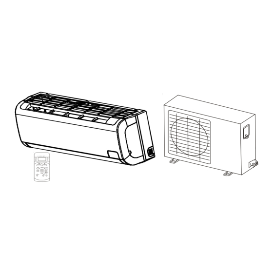
INSTALLATION & OPERATIONS MANUAL
SPLIT TYPE ROOM AIR CONDITIONER AND HEAT PUMP MODELS
O
Important Safety Instructions
The following symbols and labels are used throughout this
manual to indicate immediate or potential safety hazards. It is
the owner's and installer's responsibility to read and comply
with all safety information and instructions accompanying these
symbols. Failure to heed safety information increases the risk
of personal injury, property damage, and/or product damage.
HIGH VOLTAGE!
Disconnect ALL power before servicing.
Multiple power sources may be present.
Failure to do so may cause property damage,
personal injury or death.
Goodman will not be responsible for any injury or
property damage arising from improper service or
service procedures. If you perform service on your
own product, you assume responsibility for any
personal injury or property damage which may result.
IO-411
August 2011
MSC/MSH 9,000 & 12,000 BTUH • 115 VOLT
© 2011 Goodman Manufacturing Company, L.P.
5151 San Felipe, Suite 500, Houston, TX 77056
www.goodmanmfg.com -or- www.amana-hac.com
To prevent the risk of property damage, personal injury, or
death, do not store combustible materials or use gasoline
or other flammable liquids or vapors in the vicinity of thi
appliance.
To prevent heat releated illness or death, do not use this
device for unattended cooling of persons or animals unable
to react to product failure. Failure of unattended air
conditioner may result in extreme heat in area intended
for cooling, causing heat-related illness or death of
persons or animals.
Shipping Inspection
Always keep the unit upright; laying the unit on its side or top
may cause equipment damage. Shipping damage, and subse-
quent investigation is the responsibility of the carrier. Verify
the model number, specifications, electrical characteristics,
and accessories are correct prior to installation. The distribu-
tor or manufacturer will not accept claims from dealers for trans-
portation damage or installation of incorrectly shipped units.
Advertisement
Table of Contents

Related Manuals for Goodman MSH 9,000


Summary of Contents for Goodman MSH 9,000
-
Page 1: Important Safety Instructions
INSTALLATION & OPERATIONS MANUAL SPLIT TYPE ROOM AIR CONDITIONER AND HEAT PUMP MODELS MSC/MSH 9,000 & 12,000 BTUH • 115 VOLT Important Safety Instructions The following symbols and labels are used throughout this manual to indicate immediate or potential safety hazards. It is To prevent the risk of property damage, personal injury, or death, do not store combustible materials or use gasoline the owner’s and installer’s responsibility to read and comply... -
Page 2: Table Of Contents
CONTENTS • Be sure that placement of the unit allows adequate con- densate drainage. Important Safety Instructions ..........1 Shipping Inspection ............1 • Do not install near a doorway. Codes & Regulations ............2 • Ensure that the spaces indicated by the arrows is from Installation Considerations .......... -
Page 3: Rooftop Installations
• Select a location where noise, vibration and hot dis- charged air will not be an issue. • Do not install where high frequency equipment is used (wireless equipment, welding machine, medical facility) as it may interfere with the unit’s operation. Rooftop Installations If it is necessary to install the outdoor unit on a roof structure, ensure the roof structure can support the weight and that proper... - Page 4 NOTE: Install the mounting bracket and drill the holes in the Wall wall according to the wall structure and the correspond- O utdoor ing mounting points on the mounting bracket. (The Indoor mounting brackets vary according to the model.) Incorrect orientation Correct orientation of Installation Plate of Installation Plate...
-
Page 5: Outdoor Unit Installation
Indoor Unit Installation 9. Pass the piping through the hole in the wall. Do not allow piping to hold indoor unit away 10. Place the upper claw on the back of the indoor unit on from the wall. the upper hook of the installation plate. Move the indoor Never intertwine power wiring and other wiring. -
Page 6: Refrigerant Pipe Connection
Figure 14A (Figure 15A) (Figure 15B) Figure 14B MS* 9 & MS*12 Correct alignment Mounting Dimensions Outdoor Unit Dimensions Inches/mm (L1xHxW1) L2 (mm) W2 (mm) 30" x 23" x 11" 21" 11 1/2" 760 x 590 x 285 Drain joint installation Incorrect alignment NOTE: Drain joints differ slightly according to the different outdoor units. -
Page 7: Electrical
Insert tube in flare tool to measurement “A” in chart. Tightening Additional Outdoor Flare tubing as shown in Figure 19. Make sure flare is Torque Tightening Diameter (mm) free of burrs and completely formed to make a leak proof (N. cm) Torque (N. -
Page 8: Connect The Cable To The Indoor Unit
IMPORTANT NOTES: • If there are safety issues concerning the power supply, the unit should not be connected until safety issues are resolved. • Ensure that the electrical power supply is sufficient to safely power and run the unit. • Power voltage should range for 90% - 110% of the rated voltage. -
Page 9: Leak Testing (Nitrogen Or Nitrogen-Traced)
9. The means to disconnect from a power supply should be Terminals on the indoor unit incorporated in the fixed wiring and have an air gap con- tact separation of at least 1/8” (3 mm) in each active (phase) conductor. Leak Testing (Nitrogen or Nitrogen-Traced) Pressure test the system, using dry nitrogen and soapy water Model A... -
Page 10: Safe Refrigerant Handling
• When relocating the unit to another place, perform the Use caution when handling the packed valve: evacuation using a vacuum pump. • Open the valve stem unit it comes in contact against the stopper. Do not attempt to open further. •... -
Page 11: Test Running
• Grasp the panel sides and lift up the panel to an angle Test Running where it remains fixed and a clicking sound is heard. After completing the gas leak check at the flare nut connec- tions and electrical safety check, perform the test operation. •... - Page 12 Goodman Manufacturing Company, L.P. 5151 San Felipe, Suite 500, Houston, TX 77056 www.goodmanmfg.com © 2011 Goodman Manufacturing Company, L.P.