Superior STANDARD SERIES Installation And Operating Instructions Manual
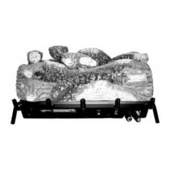
Standard series unvented gas log room heaters
Hide thumbs
Also See for STANDARD SERIES:
- Installation and operating instructions manual (16 pages) ,
- Care and operation instructions manual (20 pages)
Table of Contents
Advertisement
INSTALLER: Leave this manual with the appliance.
CONSUMER: Retain this manual for future reference.
FOR USE ONLY WITH DECORATIVE TYPE UNVENTED ROOM
HEATERS.
WARNING: IF THE INFORMATION IN THIS MANUAL
IS NOT FOLLOWED EXACTLY, A FIRE OR EXPLO-
SION MAY RESULT CAUSING PROPERTY DAMAGE,
PERSONAL INJURY OR LOSS OF LIFE.
FOR YOUR SAFETY: Do not store or use gasoline
or other flammable vapors or liquids in the vicinity
of this or any other appliance.
FOR YOUR SAFETY: What to do if you smell gas:
• DO NOT light any appliance.
• DO NOT touch any electrical switches.
• DO NOT use any phone in your building.
• Immediately call your gas supplier from a
neighbor's phone.
Follow your gas suppliers instructions.
• If your gas supplier cannot be reached, call the
fire department.
Installation and service must be performed by a quali-
fied installer, service agency or the gas supplier.
INSTALLATION AND
OPERATING INSTRUCTIONS
Unvented Gas Log Room Heaters
P/N 903623 REV. M 12/2007
MODELS
VFGL-18VSN-4 Series VFGL-18MSN-4 Series*
VFGL-18VSP-4 Series
VFGL-24VSN-4 Series VFGL-24MSN-4 Series*
VFGL-24VSP-4 Series
VFGL-28VSN-4 Series VFGL-28MSN-4 Series*
VFGL-28VSP-4 Series
WARNING: IMPROPER INSTALLATION, ADJUSTMENT, AL-
TERATION, SERVICE OR MAINTENANCE CAN CAUSE IN-
JURY OR PROPERTY DAMAGE. REFER TO THIS MANUAL.
FOR ASSISTANCE OR ADDITIONAL INFORMATION CON-
US
SULT A QUALIFIED INSTALLER, SERVICE AGENCY OR THE
GAS SUPPLIER.
WARNING: DO NOT BUILD A WOOD FIRE. DO NOT BURN
WOOD OR OTHER MATERIAL IN THESE APPLIANCES.
CAREFULLY REVIEW THE INSTRUCTIONS SUPPLIED WITH
THE DECORATIVE TYPE UNVENTED ROOM HEATER FOR
THE MINIMUM FIREPLACE SIZE REQUIREMENT.
DO NOT INSTALL THE APPLIANCE IN THIS FIREBOX, UN-
LESS THIS FIREBOX MEETS THE MINIMUM DIMENSIONS
REQUIRED FOR THE INSTALLATIONS.
This is an unvented gas-fired heater. It uses air
(oxygen) from the room in which it is installed.
Provisions for adequate combustion and ventila-
tion air must be provided. Refer to Combustion
and Ventilation Air Section, Page 3.
Due to high temperatures, the appliance should be located out
of traffic and away from furniture or draperies.
Do not place clothing or other materials on or near this
appliance.
IMPORTANT: READ AND UNDERSTAND THESE INSTRUCTIONS
COMPLETELY BEFORE INSTALLING YOUR UNVENTED ROOM
HEATER.
*Note: Manual control models are also design certified for use as vented
gas log sets.
NOTE: DIAGRAMS & ILLUSTRATION NOT TO SCALE.
STANDARD SERIES
VFGL-18MSP-4 Series*
VFGL-24MSP-4 Series*
VFGL-28MSP-4 Series*
1
Advertisement
Table of Contents

Related Manuals for Superior STANDARD SERIES


Summary of Contents for Superior STANDARD SERIES
-
Page 1: Operating Instructions
INSTALLATION AND OPERATING INSTRUCTIONS STANDARD SERIES Unvented Gas Log Room Heaters P/N 903623 REV. M 12/2007 MODELS VFGL-18VSN-4 Series VFGL-18MSN-4 Series* VFGL-18VSP-4 Series VFGL-18MSP-4 Series* VFGL-24VSN-4 Series VFGL-24MSN-4 Series* VFGL-24VSP-4 Series VFGL-24MSP-4 Series* VFGL-28VSN-4 Series VFGL-28MSN-4 Series* INSTALLER: Leave this manual with the appliance. VFGL-28VSP-4 Series VFGL-28MSP-4 Series* CONSUMER: Retain this manual for future reference. -
Page 2: Table Of Contents
TABLE OF CONTENTS WARNING: THIS APPLIANCE IS FOR IN- WARNING: FAILURE TO COMPLY WITH STALLATION ONLY IN A SOLID FUEL THE INSTALLATION AND OPERATING IN- General Information ......page 2 BURNING FIREPLACE WITH A WORKING STRUCTIONS PROVIDED IN THIS DOCU- Inventory ......... -
Page 3: Codes
• Ensure that the heater is clean when operat- openings gasketed or sealed, and ing. Excessive dust accumulation on the burner Superior Unvented Gas Log Room Heaters are and/or logs will increase the amount of carbon certified by OMNI to ANSI Z21.11.2 standard. -
Page 4: Preinstallation
2. Divide the volume of space by 50 ft b. Vent room directly to the outdoors. Refer to If damper clamp is not available, the damper determine the maximum BTU/Hr the space National Fuel Gas Code, ANSI Z223.1, Sec- may be fixed open in the following manner. Drill can support. - Page 5 Noncombustible Material Requirements with No Mantel Installed 8" or More of Noncombustible Material (A) Noncombustible Material Measurement Requirements for Safe Installation Adjustable 12" or more Adjustable canopy not required. Canopy 8" minimum to 12" Install adjustable canopy, P/N 053752 ( Figure 3 ). Less than 8"...
-
Page 6: Installation
INSTALLATION Example: The bottom of the mantel may project To avoid any movement of the heater during from the wall a maximum of 2-1/2" at a mini- operation, attach the grate to the floor of the mum of 8" above the opening. The top shelf of fireplace or firebox using the screws provided. -
Page 7: Gas Pressure Check
Gas Pressure Check Manual WARNING: DO NOT PLACE ANY LAVA Regulator Union Shut-Off Valve ROCK ON LOGS OR BURNERS. THIS MAY The heater regulator controls the burner pres- CAUSE SOOTING. ONLY PLACE LAVA sure which should be checked at the pressure ROCK ON FLOOR OF FIREPLACE. -
Page 8: Flame Appearance
Rear Burner Characteristics– The rear flames Flame Appearance CAUTION: YOU MUST KEEP CONTROL AR- should be yellow. The flames should extend EAS, BURNERS AND CIRCULATING AIR PAS- REFER TO THE OPERATING INSTRUCTIONS about 3 – 4" above the front log for natural gas SAGEWAYS OF FIREPLACE CLEAN. -
Page 9: Optional Equipment/Accessories
Wall Thermostat Kit* OPTIONAL EQUIPMENT All options are available in kit form, are easy to A wall thermostat kit is available for use with install and are packaged complete with all re- these appliances. The wall thermostat is de- quired parts and instructions. Some of the signed to be wired directly to the appliance millivolt gas control circuit and provide auto- option kits need to be fitted prior to completing... -
Page 10: Heater Specification Chart
UNVENTED GAS LOG ROOM HEATER SPECIFICATION CHART Model No. Valve Operation BTU/hr Input Gas Type VFGL - 18 MSN-4 Manual* 14,000 - 25,000 Natural VFGL - 18 MSP-4 Manual* 14,000 - 25,000 Propane/LPG VFGL - 24 MSN-4 Manual* 17,000 - 32,000 Natural VFGL - 24 MSP-4 Manual*... -
Page 11: Troubleshooting Guide
10. Slight smoke or odor during A. Vapors from paint or curing process of logs. Problem will stop after a few hours of operation. Superior recommends initial operation. running the heater with the excess ventilation for the first few hours. -
Page 12: Operating Instructions - Manual
OPERATING INSTRUCTIONS — MANUAL CONTROL MODELS FOR YOUR SAFETY READ BEFORE LIGHTING WARNING: IF YOU DO NOT FOLLOW THESE INSTRUCTIONS EXACTLY, A FIRE OR EXPLOSION MAY RESULT CAUSING PROPERTY DAMAGE, PERSONAL INJURY OR LOSS OF LIFE. A. This heater has a pilot which must be lit by hand. When •... - Page 13 Millivolt Model Pilot Piezo Flame Adjustment Gas Control Knob Knob Control Knob Locations Pilot Location Figure 15 Figure 17 Turn Control Knob to “OFF” Position (Manual) Turn Control Knob to “IGN” Position (Manual) Figure 16 Figure 18 NOTE: DIAGRAMS & ILLUSTRATION NOT TO SCALE.
-
Page 14: Operating Instructions - Millivolt
OPERATING INSTRUCTIONS FOR YOUR SAFETY READ BEFORE LIGHTING WARNING: IF YOU DO NOT FOLLOW THESE INSTRUCTIONS EXACTLY, A FIRE OR EXPLOSION MAY RESULT CAUSING PROPERTY DAMAGE, PERSONAL INJURY OR LOSS OF LIFE. A. This heater has a pilot which must be lit by hand. When •... - Page 15 Note: Knob cannot be turned from “PILOT” to “OFF” unless the knob is pushed in slightly. Do not force. Turn Control Knob to “OFF” Position Turn Control Knob to “PILOT” Position Figure 19 Figure 21 Pilot Turn Control Knob to “ON” Position Pilot Location Figure 20 Figure 22...
-
Page 16: Replacement Parts List
REPLACEMENT PARTS LIST 18N/18P 24N/24P 28N/28P Description Part No. Part No. Part No. Valve - Manual (Natural) 110331 110331 110331 Valve - Manual (Propane, L.P.G.) 110331 110331 110331 Valve, Millivolt (Natural) 903489 903489 903489 Valve, Millivolt (Propane, L.P.G.) 901917 901917 901917 Pilot (Natural) 110345... -
Page 17: Replacement Parts
REPLACEMENT PARTS NOTE: DIAGRAMS & ILLUSTRATION NOT TO SCALE. - Page 18 NOTE: THIS PAGE INTENTIONALLY LEFT BLANK. NOTE: DIAGRAMS & ILLUSTRATION NOT TO SCALE.
- Page 19 NOTE: THIS PAGE INTENTIONALLY LEFT BLANK. NOTE: DIAGRAMS & ILLUSTRATION NOT TO SCALE.
- Page 20 The manufacturer reserves the right to make changes at any time, without notice, in design, materials, specifications, prices and also to discontinue colors, styles and products. Consult your local distributor for fireplace code information. Printed in U.S.A. © 1997 by Lennox Hearth Products 1110 West Taft Avenue Orange, CA 92865 P/N 903623 REV.