Table of Contents
Advertisement
Save ThisManuam _'_
For FutureReference
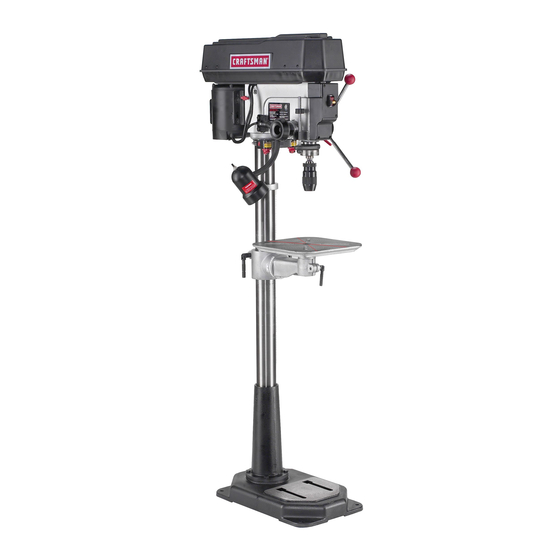
MODEL NO.
113.213151
DRmLLPRESS WiTH
MAXIMUM
DEVELOPED
1 HP MOTOR
Serial
Number
Model and serial number
may be found at the rear
of the head.
You should record
both
model and serial number
in
a safe place for future use,
FOR YOU
SAFETY:
READ ALL
INSTRUCTIONS
CAREFULLY
MOTORIZED
® assembJy
® operating
e repair parts
Sold by SEARS, ROEBUCK AND COo_ Chicago_
_L606_
U.S.A.
Part No, SP5643
Advertisement
Table of Contents

Related Manuals for Craftsman 113.213151


Summary of Contents for Craftsman 113.213151
- Page 1 Save ThisManuam _'_ For FutureReference MODEL NO. 113.213151 DRmLL PRESS WiTH MAXIMUM DEVELOPED 1 HP MOTOR Serial Number Model and serial number may be found at the rear of the head. You should record both model and serial number a safe place for future use, MOTORIZED FOR YOU SAFETY:...
-
Page 2: General Safety Instructions For Power Tools
GENERAL SAFETY iNSTRUCTiONS FOR POWER TOOLS t, KNOW YOUR POWER TOOL Z871) a! aF t_H_es 8ve, yx!ay eyegh:!_sses a,e not safety glasses P:ey oniy have mpact resistant R_a<_ ur_de_st_rx, _ file tw_er,% r_anuat _uxi iabeis affixed to the _ooI. Learn ,ts appi_cabor_ and encq.s Aiso use face o_ dust mask ff cutting oper hm_tatfo_s as w,_Has the spec&c... -
Page 3: Additional Safety Instructions For Drill Presses
additional safety instructions for drim presses Never p_ace your fingers in a position where WARNING: For your own safety, do not use your they could contact the drill or other c_ttir_g tooi drill press unti] it is completely assembled if the workpiece should unexpectedly shift or... - Page 4 ¸¸ i! iiiii i!i!iii iii:i i!iiiiil) !i i ii ii)ii !ii ! i i , :ili i Iii!iiii i : !ii i : !ililiiii : ! i iiii i ii i: 10i Use °nly accessories designed for this drill 121 This Drill Press has 12 speeds as listed below: Press to avoid se!ious injury from thrown bro;...
-
Page 5: Table Of Contents
gmessary of terms 4. Revolution Per Minute (R.P.M.) 1. Workpiece The number of turns completed by a spinning object The item on which the cutting operations is being in one minute. performed. 2. Drill 5, Spindle Speed The RPM of the spindle, The cutting tool used in the drill press to make holes in a workpiece, 3. -
Page 6: Requirements
motor specifications emectricam requirements pE nCAT O. s Th!s powe_ too! is equipped with a 3-conductor cord and grounding type plug, approved by Underwriters' This drill press is designed to use a 1725 RPM motor Laboratories and the Canadian Standards Association. only, Do not use any motor that runs faster than 1725 The ground conductor has a green jacket and is at- RPM It is wired for operation on 110-120 volts. -
Page 7: Unpacking And Checking Contents
unpacking and checking contents TABLE OF LOOSE PARTS WARNING: To avoid injury from unexpected starting or electrical shock, do not pmug the gtem Description City. power cord into a source of power. This cord A Table ......must remain unpJugged whenever you are work- B Column Support Asm .... -
Page 8: Table Of Loose Parts
,i_iii_ i I'_ _ It_r_ Descr _ p_ior_ Oty, A FeedHandle i.i:i:i..i... _--- B Key Drift.,... WrenchHex "L',3mm'''', ...: ..i:...i:, C,,_,- Wrench Rex"L ,.i: ..:..:..i E Cranki.... i: ..i.,::..., Clamp Column ....i ..D_,_ Wrench Hex Box 24rnrn .... -
Page 9: Location And Function Of Controls
ooation and function of controls 9. CHUCK... Holds drill bit or other recommended 1. BELTTENSION HANDLE... Turn handle counter accessory to perform desired operations, clockwise to apply tension to belt, turn handle 10, BEVEL SCALE . .. Shows degree table is tilted clockwise to release belt tension. -
Page 10: Assembly
assembly I WARNiNG: For your own safety, never connect FRAMING SQUARE MUST BE TRUE. l plug to power source outlet until all assembly Check its accuracy as illustrated below. I steps are completed. STRAIGHT EDGE OF DRAW LIGHT LINE ON BOARD BOARD 3/4"... -
Page 11: Installing The Table
SUPPORT LOCK INSTALLING THE TABLE TABLE t. Loosen support lock and raise table support by turning table crank cRockwise until support is at a working height level. Tighten support lock. TABLE SUPPORT RACK TABLE SUPPORT Remove protective covering from table and dis- card. -
Page 12: Mounting Motor
:KET MOUNTING MOTOR 1 Locate four (4) 8mm Dia x 20mm long hex head bolts, eight (8) flat washers, and four (4) hex nuts MOTOR among loose parts. JY _'_ BASE 2. install hex head bolts through motor bracket on head. -
Page 13: Installing Belt Guard Knob
5. Locate center pulley assembly in loose parts bag and place in proper hole. SPINDLE PULLEY 6. Locate two (2) V-belts in the loose parts bag, 7, Use speed chart inside belt guard to choose speed for drilling operation. Install belts in correct position for desired speed, The longer of the two belts is always positioned between the spindle pulley and idler pulley. -
Page 14: Motor Connections
MOTOR CONNECTIONS WARNING: For your own safety, never connect I BLACK WIRE TO ' p|ug to power source outlet until aH assembJy TERMINAL steps are completed. COPPER POST GREEN WIRE 1. Open motor connector box cover located o q under- TO GREEN SCREW side of motor using a flat blade screwdriver. - Page 15 2. Slide the chuck up over the arbor as illustrated. SPINDLE SUPPORT LOCK 3. Unlock support lock and raise table so its about two (2) inches below tip of chuck. 4, Turn chuck sleeve clockwise and open jaws in chuck completely. 5, Turn feed handles counterclockwise and force...
-
Page 16: Installing Light Bulb
|NSTALUNG LIGHT BULB than 60 watt) into the ¸¸¸_V¸¸ : : _iill i_:_ _ _i_I _i_i_i,_i_ i ,. _ _ _i:_i!i_i_i_ _!_ i_ _ _ ADJUSTING THE TABLE SQUARE TO HEAD NOTE: The combination square must be 'true. "Unpacking Checking Contents"... -
Page 17: Getting To Know Your Drill Press
getting te know your dri_Spress FEED SPRING FEED ADJUSTMENT SPRING SPRING BELT GUARD DRILL SPEED TABLE (nNSJDE BELT LIGHT "ON-OFF" GUARD) SWITCH DRILL "ON-OFF" SWITCH BELT TENSION LOCK HANDLE CHUCK BELT TENSION LOCK HANDLE _BLE BEVEL LOCK (UNDER TABLE) BELT TENSION HANDLE SUPPORT LOCK... - Page 18 T_I_ Diili Press has t2 sp_ed_ as listed belowi see inside of be!t guard for specific placement of belts ..o_n_...,u, ,,,,,D°_ 990 RPM on pulleys. ¸ 340 RPM 1550 RPM i_i,_ii_ i_i i '_i_ 390 RPM 1620 RPM 510 RPM 1900 RPM 600 RPM 2620 RPM...
-
Page 19: On-Off Switch
27. ORILL "ON-OFF" SWITCH ..Has Socking fea- ture, THIS FEATURE IS INTENDED TO HELP PREVENT UNAUTHORIZED POSSIBLE HAZARDOUS CHILDREN OTHERS. Insert KEY into switch. NOTE: Key is made of yellow pmastic. To turn drill ON . Insert finger under switch lever and pull. ®... -
Page 20: Drilling To A Specific Depth
DRiLLiNG TO A SPECIFIC DEPTH To drill a BLIND hole Inot all the way through) to a given depth, proceed as follows. 1. Mark the depth of the hole on the side of the work- piece. 2. Loosen the depth scale lock. 3. -
Page 21: Removing Chuck And Arbor
DEPTH SCALE LOCK 3. Turn the depth scale clockwise until it stops. 4. Tighten the depth scale lock. 5. The chuck will now be held at this depth when the feed handles are released. :ALE ARBOR SPINDLE KEY HOLE LOCKING COLLAR QUILL KEY REMOVING... -
Page 22: Re-Installing The Chuck And Arbor
RE-INSTALLiNG THE CHUCK. AND ARBOR C_ea_ the tapered surface on the arbor with a clean cloth, Make sure there are no foreign particles stiCK- _ng to the surface. The slightest piece of dirt on th_s surface will prevent the arbor from seating properly This will cause the drill to "wobble."... -
Page 23: Basic Drill Press Operation
operation basic press __ Securely lock Head and Support to Column, Follow the foilowing instruction, s foroperat ng you_ drll Table Arm to support, and Table to Tab!e press toget the best _esu ts aridto Rin}r__ ze t!e ikeli before operating drill press. -
Page 24: Positioning Table And Workpiece
POSITiONiNG TABLE AND WORKPmECE Lock the table to the column in a position so that the tip of the drill is just a little above the top of the work- piece. Always place a piece of BACK-UP MATERIAL (wood plywood . -
Page 25: Tilting Table
TILTING TABLE To use the table in a bevel (tilted) position, loosen BEVEL LOCK the set screw under table bevel lock with a 3mm Hex "L" wrench• Loosen bevel lock with the 24mm flat wrench. Tilt table to desired angle by reading bevel scale. Re- tighten bevel lock and set screw. -
Page 26: Maintenance
maintenance ¢::: WARNING: For your 0wn safety, turn switch 1 'OFF" and remove plug from pov_er source out'_ let before maintaining or lubiricating your drill I Frequently blow out any dust that may accumulate in, side the motor. A coat of furniture-type paste wax applied to the table and column will help to keep the surfaces clean. -
Page 27: Trouble Shooting
troubWe shooting WARNING: For your own safety, turn switch "OFF" and always remove pUug from power source outlet-] before troubge shooting. ® CONSULT YOUR LOCAL SEARS SERVICE CENTER IF FOR ANY REASON MOTOR WILL NOT RUN. PROBABLE CAUSE REMEDY TROUBLE 1. - Page 28 PARTS LiST FOR CRAFTSMAN 15" DRILL PRESS MODEL NO. 113.213151 .,...49 FIGURE 1 PARTS LiST...
- Page 29 PARTS LiST FOR CRAFTSMAN 15" DRILL PRESS MODEL NO. 113.213151 Always order by Part Number--Not by Key Number "=O FIGURE 1 PARTS LiST Part Part Description Description 817317 816755-4 Lever-Adjusting Screw-Pan HD M5 x 0.8-8 STD835016 * Screw-Hex HD. M8 x 1.25-16...
- Page 30 PABTS LIST FOR CRAFTSMAN 15" DRILL PRESS MODEL NO. 113.213!51 Always order by Part Number-Not by Key Number FIGURE 2 PARTS L_ST KeY i Description Description No ; ..821734 817325 Knob InsertPulley 816755-3 Screw-PN HD, M5 × 0,8-8...
-
Page 31: Repair Parts
PARTS LeST FOR CRAFTSMAN 15" DRILL PRESS MODEL NO. 113.213151 Always order by Part Number--Not by Key Number FIGURE 3 PARTS LIST Part ..Part Description uescrlptlorl 81 7309 Locknut M17x 81 7310 Ring-Locking 817339 Key-Chuck 81 7311... - Page 32 PARTS LIST FOR CRAFTSMAN 15" DRILL PRESS MODEL NO. 113.213151 °_---. Always order by Part Number--Not by Key Number FIGURE 4 PARTS LIST Key I Description Description No I ..--,--,=--,---4 ---- 817478 Collar-Rack 817288 Pin-Gear 820245 Screw-Hex Soc. Set Screw-Hex HD.
- Page 33 NOTES...
- Page 34 NOTES...
- Page 35 NOTES...
- Page 36 MOTORIZED For the repair 8r repJacement parts you need Call 7 am - 7 pro, 7 days a week MODEL I -eOO-3GG-PART 113.213151 (1-800-356-72781 DR_LLPRESS WITH MAXaMUM DEVELOPED ] HP MOTOR Forin-home major brand repair service Call 24 hours a day, 7 days a week 1-8OO-4oRBPA|R (1-800-473-7247) The model...